

Page 1
A U T O M A T I C S
®
4242 Baldwin Boulevard
Corpus Christi, Texas
USA 78405-3399
Tel: 800-531-3111, 361-888-5591
Fax: 800-531-3108, 361-888-6510
www.hortondoors.com
The Automatic Choice
ARCHITECTURAL DETAILS
POWER SWING DOOR OPERATORS
HD-Swing Series 4100-IG
In Ground Operator - Single & Pair, Inswing & Outswing
®
B2.9
Aug 12
Installation and Operation
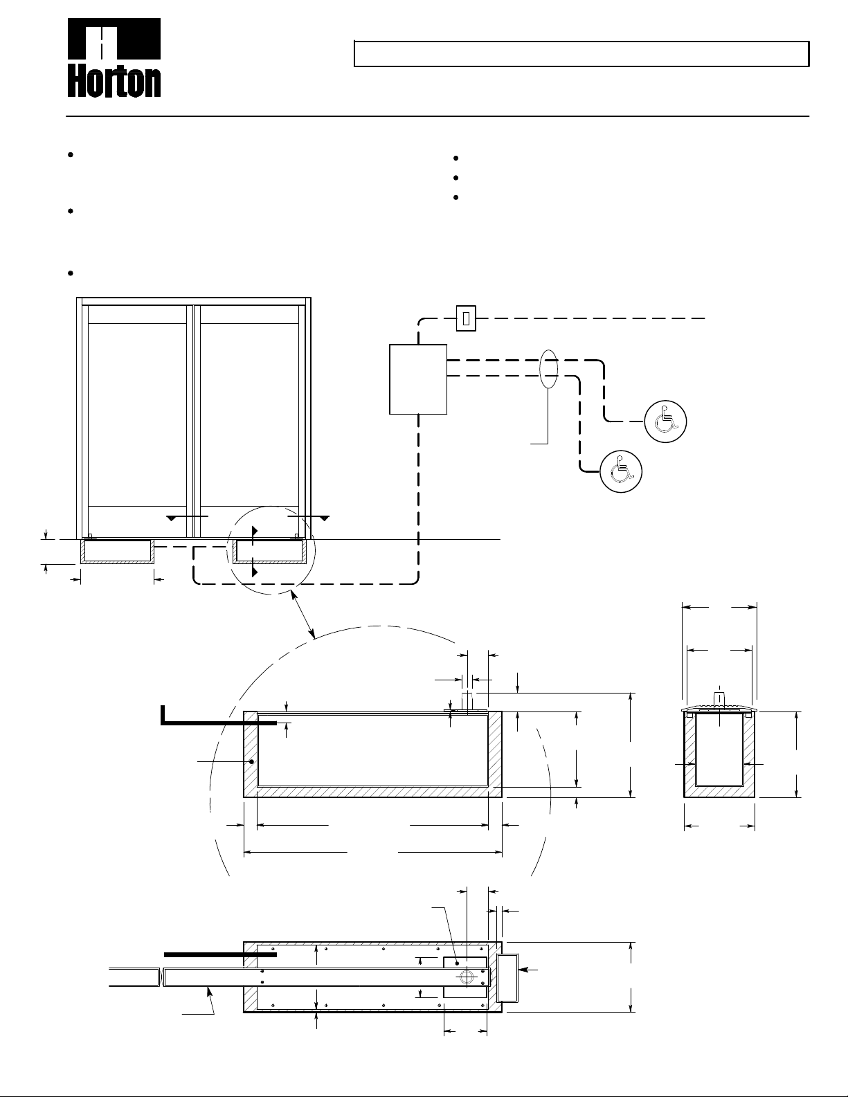
Operator to be isolation mounted and concealed in a stainless steel case
in the floor of the existing door frame or wall. Door Arms to be furnished
specific to the door mounting hardware. Frame and door panel to be
provided by others.
Electrical: Provide 120 VAC , 60 cycle, single phase, 15 amp service
(in conduit) to each swing door unit on a dedicated 20 amp circuit
breaker routed into operator. Provide liquid tight connection, conduit
and wiring. Maximum operator current draw is 3.15 amps
Unit to be actuated by push button or push plate (see p.B1.4).
8" (Typ)
Door Requirements
Door Weight - Maximum 250 lbs
Door Width - Minimum. 25
Hinge - Butt Hung, Center Pivot or Offset Pivot
For additional equipment information see Architectural Specifications
starting on p. B8.1.
120 VAC 15 AMP
power supply.(By E.C.)
Remote
Mounted
Horton
Control
Interior Switch
22 Ga. 2 wire to
activation device
(by E.C.)
Exterior Switch
'1'
Finish Floor
2'-0" (Typ)
Typical Elevation
Pair shown. Singles av ailable.
Liquid Tight
Conduit by
Others
Grout in Place
1 1/4"
Liquid Tight Conduit
by Others
'2'
1 1/4"
6" (Top of Case)
1" Output Shaft
1'-9 1/2" Case
2'-0" Pit
Removable
Cover
3 3/4"
1/8"
7"
Threshold
2"
1 3/4"
7" Case
9 3/4"
1 1/4"
1"
6"
(Top of
Case)
4 1/2"
6 1/2"
Pit
8" Pit
Vertical Section '2'
2"
1/2" Face of Jamb to Block Out
Frame by
Others
6 1/2" Pit
Doors by Others
Note: Center Pivot Shown. For
Off-set Piv ot Configuration
Consult Factory.
1/4" (Typ.)
Horizontal Section '1'
4"
Horton Automatics reserves the right to improve the
product and change its specifications without notice.
Dimensions given in U.S. inches followed by
millim eters in parenthesis.
 Loading...