

Page 1
HortiMaX-Go!
User Manual
SV 0.0 18/07/20 17
160212MAN040
96000001
Page 2

HortiMaX B.V. Mailing address
Honderdland 131 P/O box 33
2676 LT Maasdijk 2676 ZG, Maasdijk
The Netherlands The Netherlands
Tel: +31(0)15 3620300 Website: www.hortimax.com
E-mail: info@hortimax.com, sales@hortimax.com,
helpdesk@hortimax.com
All efforts have been made to ensure the accuracy of the contents of this manual.
Should any errors be discovered, however, HortiMaX B.V. would greatly
appreciate being informed of them. The above notwithstanding, HortiMaX B.V.
can assume no responsibility for any errors in this manual or their possible
consequences.
This product is subject to the General Conditions of HortiMaX B.V..
This document may not be copied or made public by means of print, photocopy,
microfilm or any other process, without the written permission of HortiMaX B.V..
Publication date: 18/07/2017 14:39 160212MAN040 Item code: 96000001
Page 3

Contents
1 Preface
4
1.1 Documentation overview 4
2 Basic navigation and icons
5
2.1 T he home screen 5
2.1.1 Tiles 5
2.1.2 Top Bar 8
2.1.3 Right-hand bar 8
2.2 Alarm screen 9
3 Setting up climate control
10
3.1 F ixed position control 10
3.2 Stage control 11
3.2.1 General information 11
3.2.2 Adjusting the stage limit values 13
3.2.3 Deactivating a stage 13
3.2.4 Setting control actions for each stage 13
3.2.5 Setting periods 14
3.2.6 Humiditycontrol 16
3.3 F ullyautomatic ventilation control 18
3.4 Manual control 19
4 Setting up irrigation control
20
4.1 Required settings 20
4.1.1 Duration and volume 20
4.1.2 Assigning valvesto valve groups 21
4.1.3 Dosing fertilizers 22
4.2 Star t conditions 23
4.2.1 Manual starts 23
4.2.2 Pre-progr amming start conditions 23
5 Smart Switches
25
5.1 Smart manual control switches 26
5.2 LED indications 26
5.3 F ieldbus 27
5.4 Meteo-Go! 28
5.5 MTV-Go! 28
6 Icons legend
29
6.1 System 29
6.2 Program components and shortcuts 29
6.3 Climate controls 30
6.4 Irrigation controls 30
6.5 Other software components 31
Page 4
1 Preface
Welcome to the user manual for the HortiMaX-Go!. This manual is intended for users.
It contains specific information on how to operate the HortiMaX-Go!.
The HortiMaX-Go! is an easy-to-use and affordable control computer designed
specifically for the horticultural sector. With the HortiMaX-Go!, you can control both
the irrigation and the climate inside your greenhouse. The HortiMaX-Go! is easy to
customize by choosing unique ‘Smart Switches’ that can be installed in a plug-andplay manner.
The HortiMaX-Go! is also a breeze to operate using its touchscreen display. By using
the CloudBox and the HortiMaX-Go! app, you can even operate the HortiMaX-Go!
remotely with your smartphone. You can manage your Cloudboxes, controllers and
app users on the HortiMaX-Go! CloudBox Portal.
This manual was originally published in Dutch and English.
1.1 Documentation overview
For more information, please consult the online help or the following manuals:
HortiMaX-Go! installation manual
The OEM (Original Equipment Manufacturer) documentation provided
Scan the QR code to access the online help.
help.hortimax-go.com
HortiMaX-Go!
4
Page 5
2 Basic navigation and
icons
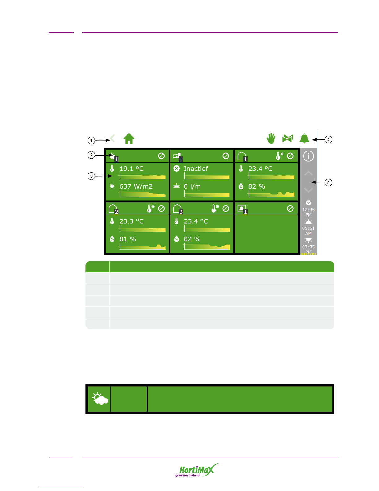
2.1 The home screen
The home screen of the HortiMaX-Go! software contains a number of standard
features. The main standard features are the tiles, top bar and right-hand bar.
No. Description
1 Breadcrumb trail
2 Tile header
3 Tile body with information
4 Direct access to: manual control, valves and alarms
5 Right-hand bar
2.1.1 Tiles
Most of the system's display is taken up by tiles. Tiles provide access to the various
controls of the HortiMaX-Go!. The tile header and the tile body contain information
about the current situation in your greenhouse. The home screen may show the
following tiles:
MeteoGo!
The tile in the upper left corner shows the weather station.
HortiMaX-Go!
5
Page 6
Irrigation
unit
If an irrigation unit is present, it will be shown on the second
tile. Under this tile, you will find all the irrigation control
settings.
Climate
zone
Each zone (greenhouse compartment) has its own tile on the
home screen. The zone number is indicated in the black box
at the bottom right of the icon. Under a zone tile, you will
find all the controls belonging to that zone.
Alarm
contact
The Alarm contact tile provides direct access to the Alarm
contact settings. The Alarm contact is a shared function for
all climate zones and the irrigation unit.
Tile header
On the left-hand side of the tile header, you will find the icon of the control or control
component and the zone number.
On the right-hand side of the tile header, icons may be shown with the following
meanings:
The control is set to automatic mode. This means that the controller will
take automatic control actions based on the pre-programmed software
settings.
The control is set to a fixed position.
No connection could be established with the hardware associated with the
control. This is a serious situation that will trigger an alarm.
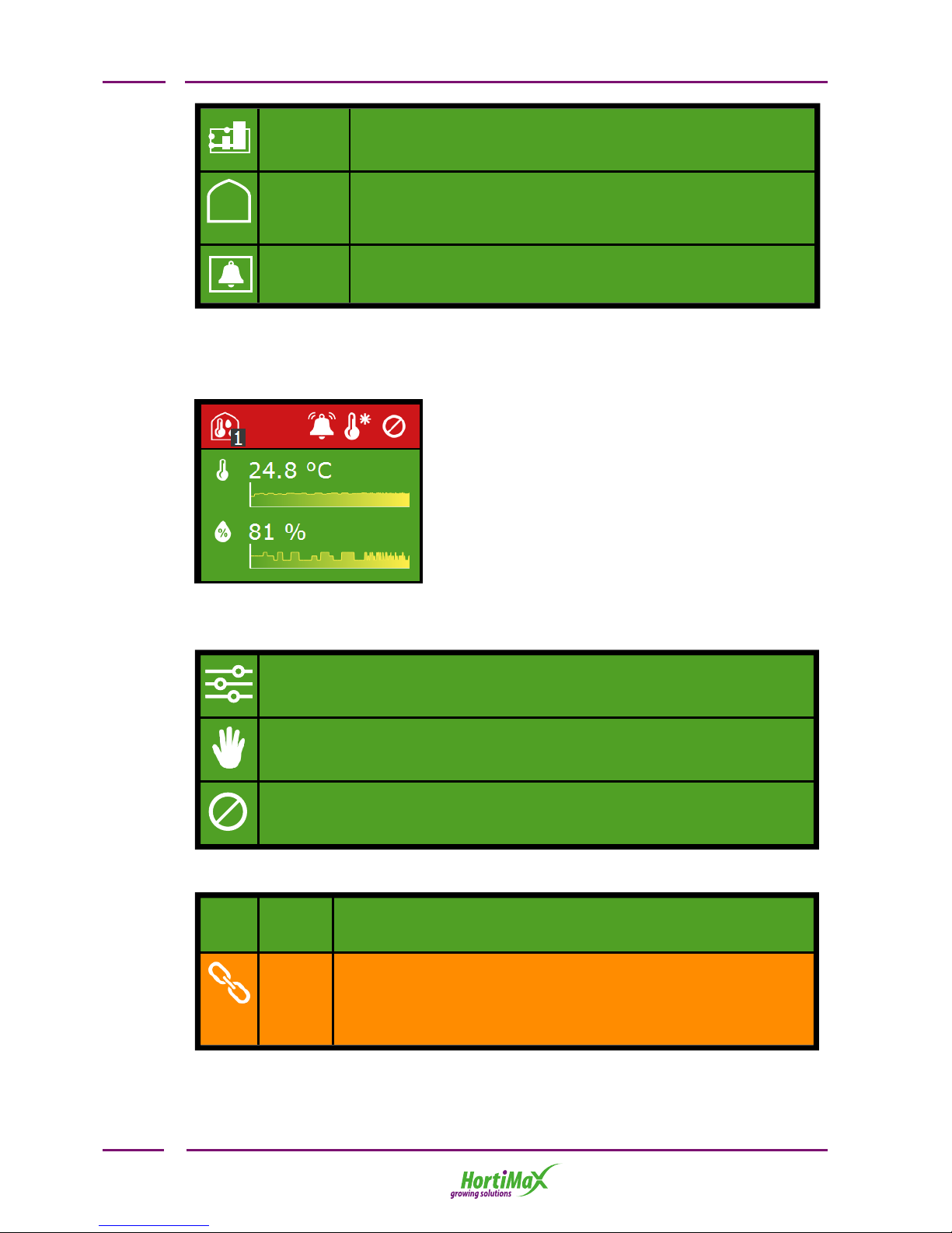
The tile header can have three colours: green, orange and red.
Green If the header is green, then the control is active and the
situation is normal. A control can be set to automatic mode or
a fixed position.
Orange If the header is orange, then a system in one of the underlying
levels has been set to manual control. As a result, the
controller is unable to control the connected equipment. This
could cause a hazardous situation as the rain, gale or other
overrides will not be applied.
HortiMaX-Go!
6
Page 7
Red If a tile header turns red, it means that an alarm has been
triggered. In that case, an bell icon will also appear on the
right-hand side.
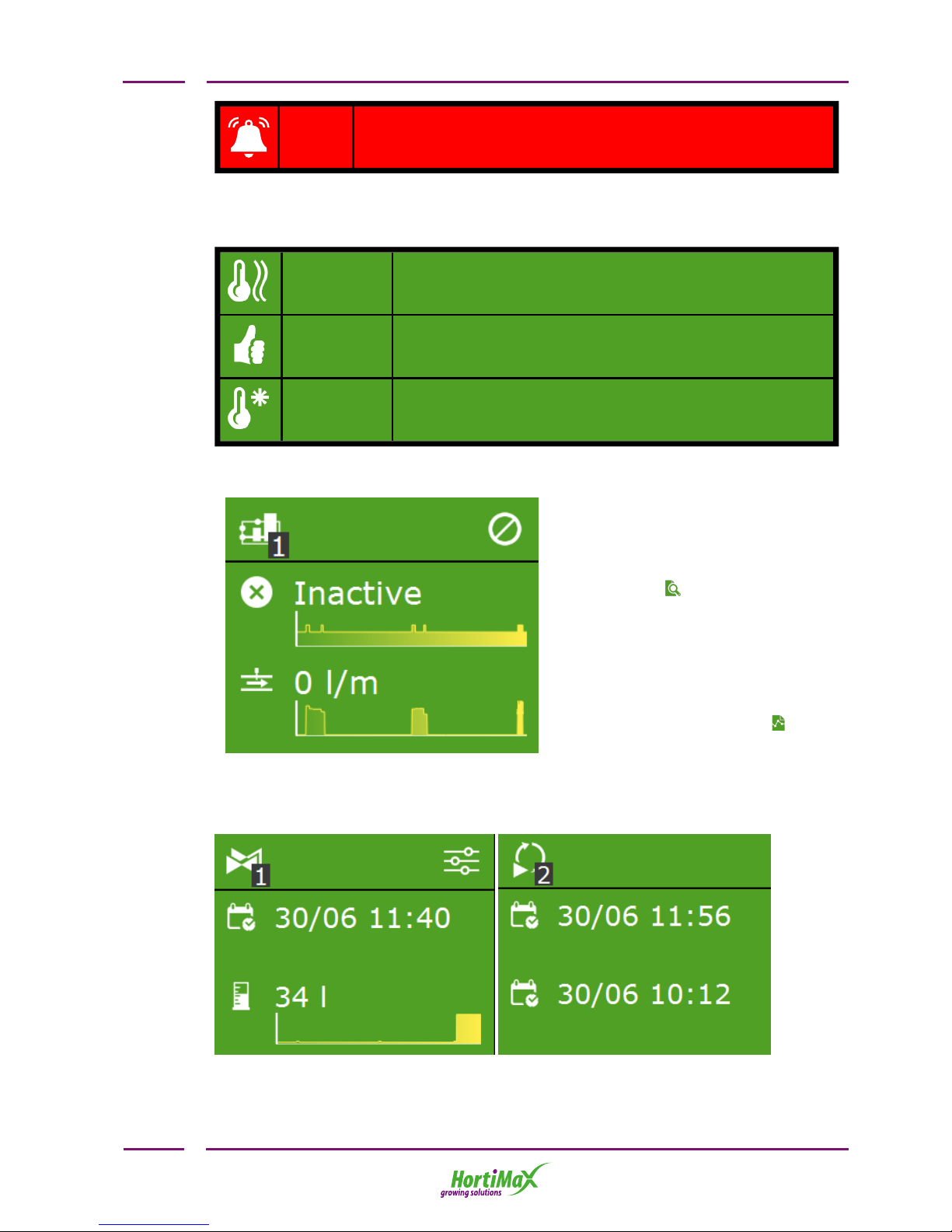
Stage information
The tile header shows the active temperature stage.
Heating
stage
The zone temperature is below the desired temperature.
Neutral
stage
The zone temperature is within acceptable limits.
Cooling
stage
The zone temperature is above the desired temperature.
Tile body
The tile body shows readouts and trend
graphs. The readouts show the main
readout values for the relevant control.
If you tap the tile and then open the
readout screen , you can view all the
current readouts for that control.
The trend graphs indicate the relative
trend over the last 2 hours. For more
detailed information on a certain
readout value, open the graphs
program by tapping this icon: .
In the irrigation program, the tile bodies show other information. At the top,
information on the next irrigation cycle (date and time) is shown. At the bottom,
information on the last irrigation cycle (volume or time) is shown:
HortiMaX-Go!
7
Page 8

2.1.2 Top Bar
The breadcrumb trail on the left-hand side of the top bar shows your location within
the software. Each icon in the trail represents a tile of a particular control. The
number indicates which zone or control you are looking at. If you tap an icon in the
breadcrumb trial, you will be taken directly to the corresponding tile.
The breadcrumb trail leading to stage control for the roof screens might look like this:
In words: Home screen => Zone 1=> Roof screen 1 => Stage control.
Three icons may be shown on the right-hand side of the top bar. These are direct links
to:
Fixed
position
control
The fixed position control screen provides an overview of the
zone controls. Here you can opt for a fixed position or
automatic control. If you select automatic control, the
controller will use the stage control settings.
Valve
group
manual
control
The valve group manual control screen shows information
about the status of the valves in each valve group. It also
includes a start button to activate a valve group immediately.
Alarm
screen
The alarm screen shows all active alarms. The bell icon shows
the number of active alarms and whether the system bell is
active.
2.1.3 Right-hand bar
The bar on the right-hand side of the screen always contains the same information
and allows you to access a number of basic settings.
Help
button
This button opens a help screen with a QR code. If you scan
the QR code, the corresponding online help page will open.
Arrow
up
This button is enabled (white) if there is more information
available above the information shown.
Arrow
down
This button is enabled (white) if there is more information
available below the information shown.
System
time
Tap this button to change the system settings such as
language, location, and system time. This is also where you
will find a scanning screen where you can have the
HortiMaX-Go! scan for Smart Switches. Below this button,
the current time is shown.
HortiMaX-Go!
8
Page 9
Sunrise The time that the sun will rise today.
Sunset The time that the sun will set today.
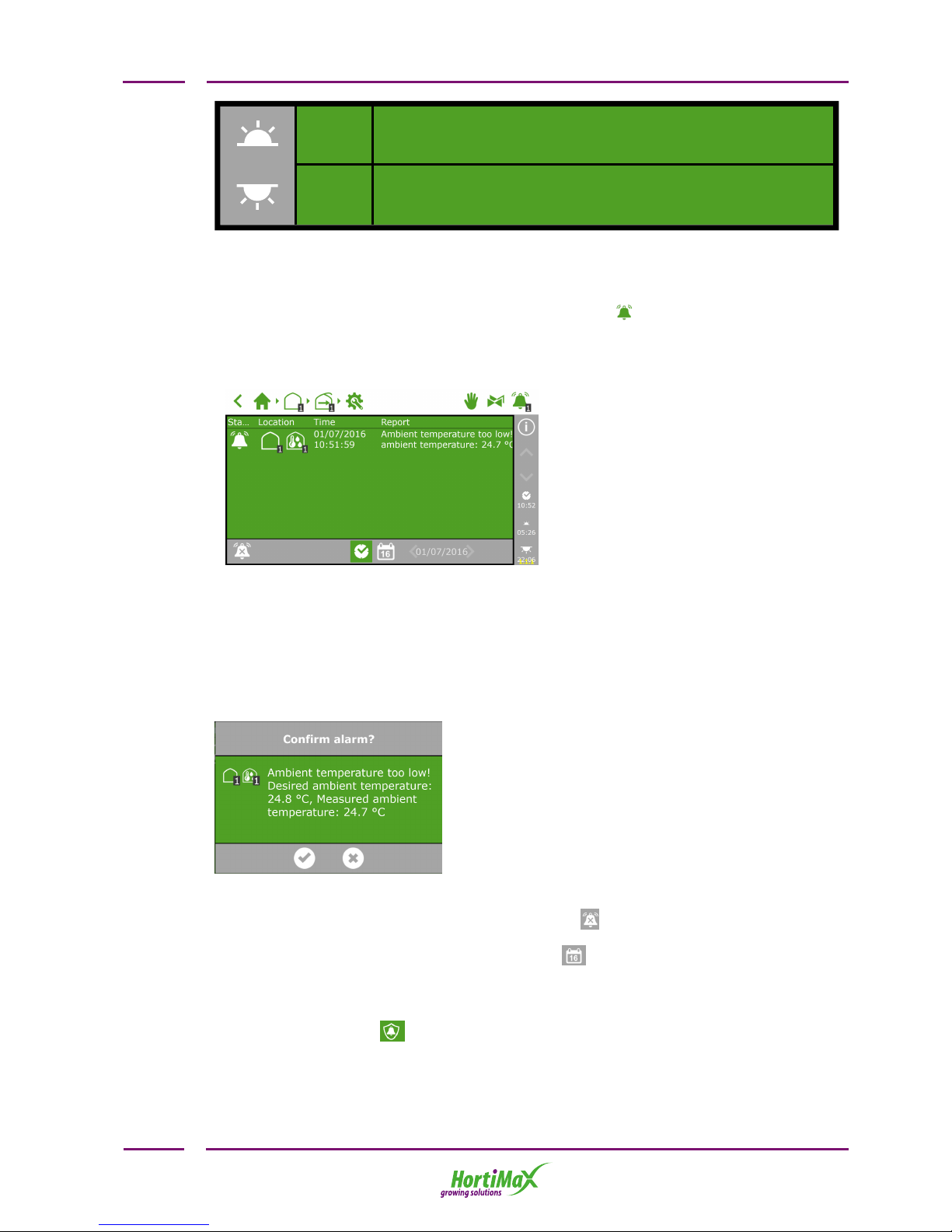
2.2 Alarm screen
You can open the alarm screen by tapping the bell icon on the right-hand side of
the top bar. This screen contains information about your current alarms and your
alarm history.
If you tap an alarm on the alarm screen, a pop-up screen will open with detailed
information about the alarm. This is also where you can acknowledge the alarm. If
you acknowledge an alarm, it will be reset. However, if the cause of the alarm has not
yet been resolved, the alarm will probably return almost immediately.
Alarms are never removed from the list automatically, even if an alarm situation has
been resolved.
If an alarm situation has not yet been resolved and the alarm is still active, you can
disable the alarm bell by tapping the 'bell off' icon .
To view historical alarms, tap the calendar icon and select a date. All historical
alarms are saved up to one year.
Alarm values can be set for various controls. These alarm limits can be found under
the tiles with the icon: .
HortiMaX-Go!
9
Page 10
3 Setting up climate
control
Once your HortiMaX-Go! has been commissioned, all the connected controls are set to
safe fixed positions. Vents and screens are set to 0%. Various other equipment such
as heaters or the cooling system are switched off. To enable automatic climate
control, you need to complete two steps: first set the desired control values
(temperature, relative humidity (RH) , Watts, CO2), and then switch the system to
automatic control.
Irrigation control is not activated automatically. To activate it, you must first set the
start conditions for irrigation and the fertigation recipes (specifying the ratios in
which your fertilizers are to be dosed). How to set up automatic irrigation control is
described in "Setting up irrigation control" on page20. This chapter first describes
how to set up and activate automatic climate control.
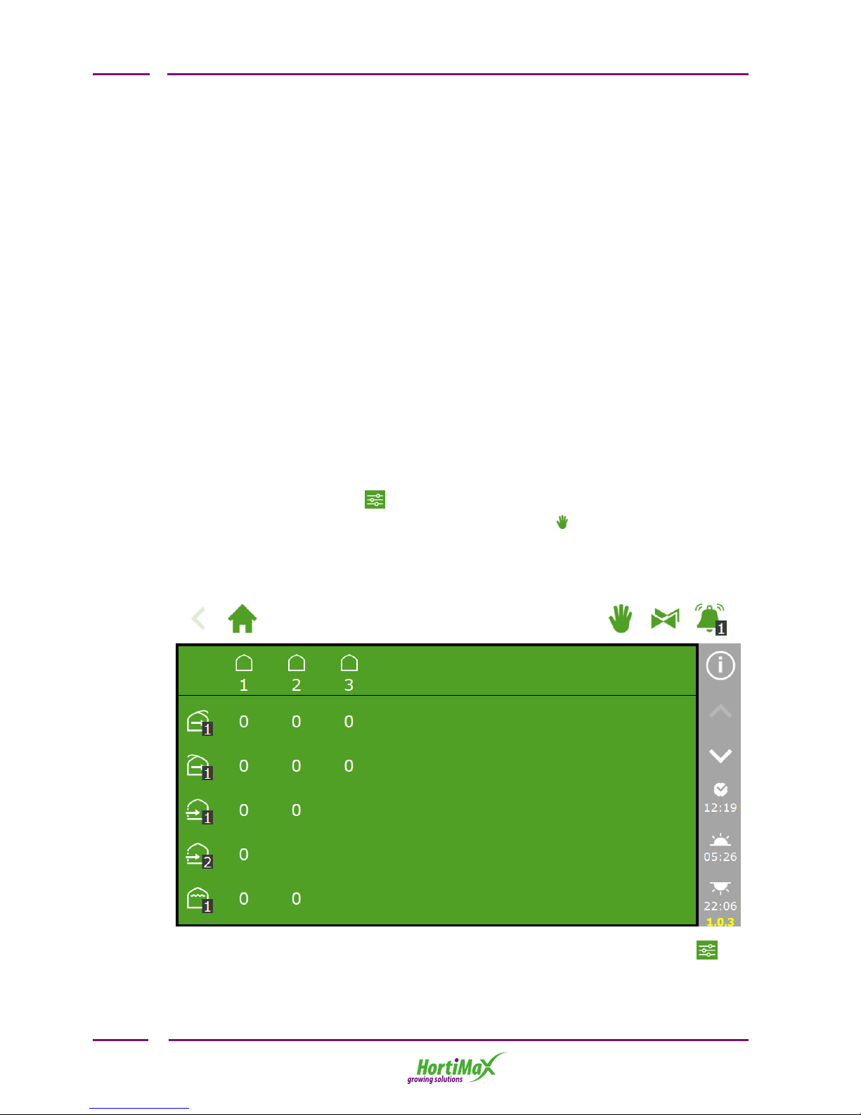
3.1 Fixed position control
The various climate control components are set to a fixed position (0 or off) by
default. On the stage screen , you can change the fixed position of each zone and
control. If you tap the 'Hand' icon (on the right-hand side of the top bar), an
additional screen will open showing all the connected climate controls.
Fixed position screen:
If you tap a value, a screen will open where you can activate automatic control or
select a fixed position.
HortiMaX-Go!
10
Page 11

To enable automatic control, certain control values need to be set. You can do
this on the stage screen that can be accessed from the various control screens
of each zone.
Other settings can be found under the control-specific tiles , .
Fixed positions are not adjusted for the climate conditions inside your
greenhouse and apply for the entire day. Fixed position control is designed to
achieve a desired position quickly without changing any of the other software
settings. Unlike with the manual control mode on the switch cabinet, the gale,
rain and frost overrides will continue to be applied if fixed positions have been
selected.
3.2 Stage control
3.2.1 General information
The HortiMaX-Go! controls the greenhouse climate based on pre-defined 'stages'. The
stage screen is represented by the icon . You can open this screen from the various
other control screens.
The stage screen is where you set:
The desired temperature and humidity (target values)
How the temperature and humidity are to be controlled (controls)
When the above settings should apply (periods)
The stage screen allows you to enter and adjust the temperature and humidity
settings. Temperature control works based on three possible situations (called
stages): the temperature is too low, the temperature is acceptable or the
temperature is too high. When it is too cold, the heating stage will be active, and
when it is too hot the cooling stage will be active. When the temperature is
acceptable, the neutral stage will be active .
HortiMaX-Go!
11
Page 12

Depending on your greenhouse equipment and design, there are various ways of
cooling or heating your greenhouse. The ambient temperature can be lowered by
opening the roof or side vents, switching the heating system off, switching the cooling
system on, or a combination of these actions. The control actions that are applied
during each stage will depend on your settings on the stage screen. These settings
can be programmed for the entire day or for up to four daily periods.
The stage screen can be opened from the individual control screens.
No. Description
1 Breadcrumb trail: shows for which zone (zone 1 in the above screen) the
stage screen has been opened
2 Icons for fixed position and the various stages
3 Stage limit value
4 Control with specific settings
5 Period for which stage control applies
6 Buttons to display or hide the manual control and humidification columns
The top bar of the stage screen shows the different stages. In the screenshot above,
there are two cooling stages and two heating stages. You can set multiple heating
stages (up to 2) and cooling stages (up to 6). This allows you to control the ambient
temperature even more accurately.
The stage screen resembles a table. The top bar shows the stages with the
corresponding values. In the screenshot below, the desired ambient temperature is
between 18.0°C and 20.0°C .
When the temperature drops below 18.0°C, the first heating stage will start. When the
temperature rises above 20.0°C, the first cooling stage will start. When the
temperature rises above 22.0°C, then the second cooling stage will start.
HortiMaX-Go!
12
Page 13

3.2.2 Adjusting the stage limit values
You can adjust the limit value of a stage or disable a stage in each period. Tap the
stage icon for which you want to adjust the limit value:
You can now set the limit value at which the stage will be activated:
The heating stage will be activated as soon as the measured ambient temperature
drops below the pre-set limit value. The cooling stages will be activated as soon as
the ambient temperature rises above the pre-set limit values. Humidity control works
in a similar way.
If the limit values are set too close to one another, it may result in erratic
control due to the stages changing too frequently.
The minimum switching time between stages is 10 minutes by default. This will
prevent the stages changing too frequently.
3.2.3 Deactivating a stage
To deactivate a certain stage for the selected period, simply tap the icon: .
3.2.4 Setting control actions for each stage
After setting the limit values, you can specify the desired position or control action to
be taken for each system. For systems that switch on or off, you can select either on
or off. For systems that open or close (roof vents, side vents, internal screens and
external screens), you can select either a position from 0 to 100% or the automatic
mode. How the automatic mode works depends on the specific function of the
connected equipment.
HortiMaX-Go!
13
Page 14

For the central heating system , you can set either a value for
the pipe temperature or select the automatic mode . In the
automatic mode, the pipe temperature will vary to achieve the
pre-set stage temperature.
For CO2control , you can set a maximum value in ppm above
which CO2dosing will switch off. A different maximum value can
be set for the temperature stage. For example, when it is very
warm and the vents are wide open, CO2dosing will be very costly.
CO2dosing is generally not necessary for the night period. You
would normally disable CO2dosing for the night period or select an extremely low
target value.
3.2.5 Setting periods
The HortiMaX-Go! allows you to set four periods per 24 hours. By setting different
periods, you can have target values vary throughout the day. You can enter the period
start times in clock time or in relation to sunrise or sunset. At the bottom of the stage
screen, you will see the start and end times of the selected period:
HortiMaX-Go!
14
Page 15

If you tap the start or end time, a screen will open listing the start times of the four
periods:
By tapping the different periods, you can choose whether a period should start based
on clock time or relative to sunrise or sunset.
Start time based on clock time
Start time before sunrise (e.g. 1 hour before sunrise)
Start time after sunrise (e.g. 1 hour after sunrise)
Start time before sunset
HortiMaX-Go!
15
Page 16

Start time after sunset
The two circles next to the start times represent the 24-hour clock. White represents
the day, black represents the night. The coloured sections with numbers in the inner
circle indicate the periods.
If periods overlap, the highest period number will apply.
Setting the day and night periods
We recommend using at least two periods for most crops. Setting two periods for the
day and the night is very simple. To do this, select the following settings:
If you delete periods and then add them again, the corresponding settings will
be retained. Check whether the pre-set values are correct for all the selected
periods.
3.2.6 Humidity control
The basic settings for humidity control can be found on the stage screen. You can
open these settings by tapping the droplet at the bottom right of the screen: .
HortiMaX-Go!
16
Page 17

Three columns will appear:
The icon is the limit value for the humidification stage; this means it is too dry in
your greenhouse.
The icons are the limit values for the dehumidification stage; this means it is too
humid in your greenhouse.
In the above example, the air vents on the leeward side will be limited to a maximum
position of 20% if the relative humidity (RH) drops below 60%. If the RH rises above
80% or 90%, the minimum vent position will be 2% and 5% respectively. If the RH
rises above 90%, the vent position on the windward side will be at least 3%.
The humidity settings for the vents and screens act as limitations, i.e.
minimum or maximum positions. Although a higher or lower value may be
desirable based on the ambient temperature, the vent or screen position may
be limited because of the current humidity level. The gale, rain and wind
overrides have priority over the humidity settings.
Control example:
When it is too dry or too hot in your greenhouse, you can switch on the humidification
system if you have one. In the example below, the humidification system will switch
on if the ambient temperature rises above 25°C or the RH (relative humidity) drops
below 60%. If the RH rises too high (above 90%), the humidification system will
switch off:
HortiMaX-Go!
17
Page 18

The controller does not check whether the entered stage settings make sense.
If the stages are not set correctly, the system may, for example,
simultaneously cool and heat your greenhouse under certain conditions. That
is why you should always check the stage settings that you have entered
carefully.
3.3 Fully automatic ventilation control
Automatic control is available for a number of components. If automatic control is
available, the stage screen will show the following icon: .
The automatic ventilation program adjusts the vent position based on the ambient
temperature. This means that as the temperature rises, the further the vents will
open. The automatic ventilation program takes into account the outdoor conditions
such as wind speed and temperature. This allows the controller to maintain the ideal
greenhouse climate.
Example
In the figure above, ventilation control has been set to automatic mode and is
currently active.
In the fixed position column , the 'stage control’ option has been selected. If
the ambient temperature rises above 22°C, the controller will automatically open the
vents further. In this example, automatic control will not be activated in the first
cooling stage, but in the cooling stage where the automatic mode has been
selected (in this example that is the second stage).
The automatic ventilation program can be overridden by various factors. A humidity
override may have been set in the stage screen, which means that a minimum or
maximum vent position may apply. Other automatic overrides may have also been
set in the advanced settings of a control screen ( ). Rain, gale-force winds and frost
may also cause overrides on the vent position to be applied.
HortiMaX-Go!
18
Page 19

3.4 Manual control
Depending on the Smart Switch, the manual control knob has either three modes
(On/Off/Auto) or five modes (On/Off/Auto/Open/Close). If the manual control knob is
set to the ON position, all controls will be disabled. The tile headers of the controls
will turn orange and display the following icon: . One or more switches are not in
automatic mode as shown below:
HortiMaX-Go!
19
Page 20

4 Setting up irrigation
control
The irrigation controls are located under the irrigation unit tile. This tile shows
whether the unit is active and the current water flow rate (if measured).
Irrigation control consists of a number of components, including the irrigation unit
and valve group settings. The valve groups allow you to set the irrigation start
conditions and fertigation recipes for each pre-defined time period. The irrigation
program also enables you to assign irrigation valves to valve groups and it can
display detailed information about the valve and valve group activity.
4.1 Required settings
In order to activate the irrigation program, there are certain settings that must be
entered such as the irrigation quantity of each valve group and assigning valves to
valve groups. The desired EC value must also be set so the system is able to dose
fertilizers.
4.1.1 Duration and volume
The amount of water that is applied during each irrigation cycle is shown on the
settings screen for automatic irrigation . You can set the water application in time
(duration) or in volume (provided a litre counter is present). To activate irrigation
control, at least one of these two values must be set.
HortiMaX-Go!
20
Page 21

4.1.2 Assigning valves to valve groups
The irrigation program works based on valve groups. A valve group consists of the
valves you have selected together with the start conditions and irrigation settings that
you have programmed for those valves.
To assign valves to a valve group, follow this route in the software:
Then tap the tile with the icon: .
Then select the valves that you wish to assign to the valve group by tapping them. A
white border will appear around the selected valves.
HortiMaX-Go!
21
Page 22

The irrigation program includes the ability to use a separate valve group for each
valve, so you can program fertigation recipes for each individual valve.
4.1.3 Dosing fertilizers
In order to dose fertilizers, the desired EC value needs to be set for each valve group.
The EC (and pH) settings are located at the bottom of the automatic irrigation screen
that you can access by tapping the down arrow in the right-hand bar: .
If more than one fertilizer is used, you can set the dosing ratio of each fertilizer. The
dosing ratio is set for each valve group. By default, the irrigation program uses a
ratio of 100% for all available fertilizers. The HortiMaX-Go! supports up to four
fertilizer dosing valves.
HortiMaX-Go!
22
Page 23

4.2 Start conditions
4.2.1 Manual starts
The irrigation program includes two types of manual starts: the manual valve start
and the manual valve group start.
The manual valve start can be found in each valve group. If you select the next tile,
the ‘Assign valves’ selection screen will open. Tap the valves that you want to
activate; these will be indicated in white, and then tap the 'play' button to activate
them. The irrigation program will activate the selected valves using the recipe of the
valve group from which you opened the screen and that applies for the current period.
The tile of the manual valve start will indicate when the last manual start was
performed.
If a manual valve group start is executed, the irrigation program will activate the
valves assigned to the group and apply the pre-programmed recipe. This start
program can be found on the right-hand side of the top bar . You can activate a
valve group by tapping the 'Play’ button in the valve group activity screen. The valve
group will be activated immediately.
The screen will show which valves in the group are active. If a manual valve start is
executed, the irrigation progress of the valve group will also be displayed.
If you want to a different recipe to be applied for a manual valve start, you
can change the EC, pH and volume settings of the valve group. Don't forget to
change the settings back afterwards. An alternative method is to assign the
desired valves to a group that is still 'free'. You can program different recipe
settings for this group without changing your standard recipes.
4.2.2 Pre-programming start conditions
The irrigation program includes a number of start conditions that can be pre-set:
HortiMaX-Go!
23
Page 24

Time
start one-off
Start irrigation once on the pre-set date and time (with the
recipe settings applicable at that time)
Time
start daily
Start irrigation on the selected days at a pre-set time (with
the recipe settings applicable at that time)
Time
start interval
Start irrigation at the pre-set time with an interval of a predefined number of days.
Cyclic
start
A cyclic start applies for a particular period and valve group.
After the pre-set cycle time, the valve group will be reactivated (i.e. irrigation will start again). The cycle time will
be reset after each start (of each type).
Contact
start
The group will be activated when the selected contact is
activated.
Radiation
sum
start
The group will be activated once the pre-set radiation sum
(J/cm2) is reached. The radiation sum will be reset once the
irrigation cycle has been completed and at midnight (0.00
hours).
When automated irrigation starts are executed, the irrigation program will
always use the recipe settings of the valve group in the period that is
currently active. If no period is currently active, irrigation will not start
automatically.
HortiMaX-Go!
24
Page 25

5 Smart Switches
Smart Switches are the manual control switches used for the HortiMaX-Go!. In
addition to an electrical circuit, these switches feature a processor and software. The
Smart Switches perform specific control actions for the equipment connected to them.
The switches are advanced control devices that can process a wide range of
information, such as status and position determination and run and operating times.
The installation engineer can also connect various contacts to the switches, such as
end contacts, emergency stop contacts and thermal cut-out contacts (also called
'thermal protector contacts'). If such contacts are connected, the Smart Switch can
use the collected status information for control purposes and relay the information to
the central HortiMaX-Go! controller. This greatly enhances the system's reliability and
allows alarms to be generated instantly if something goes wrong with your
equipment.
No. Meaning
1 DIP switch for setting the Smart Switch address
2 LED indicators for bus communication
3 Manual control knob (optional)
4 LED indicators for control actions active
5 Power supply and bus connections
6 Connections for peripheral equipment
HortiMaX-Go!
25
Page 26

5.1 Smart manual control switches
The manual control knob on the Smart Switches can be used to either disable
automatic control and operate the connected equipment manually, or switch the
equipment off. If you switch to manual control, the controller will continue to keep
track of the status or position of your equipment. This unique feature means the
controller is able to monitor the current situation and the operating times of your
equipment with much greater accuracy.
When you turn the knob from manual control back to automatic control, the controller
will immediately apply the correct positions. This is unlike conventional switches that
require the controller to be reset or synchronized.
If the controller and/or bus communication are non-operational, the Smart
Switches will be unable to control the equipment automatically. However,
using the control knob, you will still be able to adjust the Smart Switches
manually, so you can turn equipment on or off or open or close it. In this
situation, the equipment positions and operating times shown by the
controller may differ from their actual values.
5.2 LED indications
The Smart Switches feature two types of LEDs on the bottom circuit board and the
switch covers. Listed below are the meanings of the various LED indications:
HortiMaX-Go!
26
Page 27

5.3 Fieldbus
The switches are connected to each other using a fieldbus system. The fieldbus
system enables digital communication between the switches and the controller via a
network cable.
Each Smart Switch in the network is assigned a unique address. This address is set
using the DIP switch during commissioning. The DIP switch has eight
toggle switches. The first three toggle switches (1-3) allow you to set the zone
number; the last five toggle switches on the right-hand side (4-8) allow you to set the
unique ID number of the Smart Switch.
A green status LED on the switches indicate whether communication is currently
active. If no communication is possible, a red LED will light up continuously. This may
have various causes:
Controller failure
Broken cable
Wrong cable used
Power failure at one of the connected switches
Failure of one or more switches
Disruption by an external factor such as a frequency controller or high-voltage
cable
Incorrect ID address (DIP switch position)
Incorrect or duplicate terminal resistance installed
Communication problems due to incorrect installation may sometimes only arise after
some time or following a system expansion. To avoid such problems, make sure to
follow the installation instructions carefully.
HortiMaX-Go!
27
Page 28

5.4 Meteo-Go!
The Meteo-Go! is the weather station of the HortiMaXGo!. This compact device is installed outside the
greenhouse and collects weather data needed for
automatic climate and irrigation control.
The following readouts are available:
Outside temperature
Solar radiation
Wind speed
Wind direction
Rain detection
Location
Relative humidity
If you have multiple controllers, they can share the data from one Meteo-Go!.
Throughout the control software, there are override settings that are
triggered by key weather readings. The purpose of these settings is to
prevent damage to your greenhouse and/or crop. Override settings are set to
safe values by default, but can be adjusted by the user. The controller also
takes the weather readings into account for maintaining the ideal greenhouse
climate.
5.5 MTV-Go!
The MTV-Go! is a sensor unit that measures the
ambient temperature and relative humidity in the
greenhouse. One MTV-Go! unit needs to be installed in
each climate zone. The ambient temperature and
humidity are essential readings in crop production,
and therefore essential for automatic climate control.
Thanks to the special fanless design of the MTV-Go!
housing and electronic sensors, the sensor unit
requires little maintenance. Although the housing is
designed to protect the internal sensors, do not spray
chemicals directly into the housing.
HortiMaX-Go!
28
Page 29

6 Icons legend
6.1 System
Home Configuration
menu
+
Configuring stage
control
Access to the
alarm screen
Access to
configuration
Network
settings
Configuring
system settings
Show QR help
code
Alarm active with bell
sounding
Alarm tile
6.2 Program components and shortcuts
Weather screen Irrigation
unit
Zone Access to fixed
position control
Access to stage
control
Temperature
is OK
Access to humidity
control
Heating stage Cooling
stage
Stage too dry,
humidify
Stage too humid,
dehumidify
Set periods Access to
graphs
Advanced settings Set counter
HortiMaX-Go!
29
Page 30

Alarm limits Readout
screen
Statistical
information
Historical information
6.3 Climate controls
Roof ventilation Windward side Leeward
side
Side
ventilation
Cooling Pad Valve Pad & Fan Screen
Central heating Central heating
mixing valve
Outside
screen
Inflation
fan
CO2valve Humidification
(fogging)
Recirculation
fan
Hot air
heater
Zone common
measurements
MTV-Go! sensor unit CO2box
6.4 Irrigation controls
System pump Filling pump EC pre-blending Irrigation
valve
HortiMaX-Go!
30
Page 31

Fertilizer dosing Acid dosing Valve group
Assign valves to
group
Valve group
status
Access to sensor
calibration
Advanced
setting
Manual valve start Time start Radiation sum start Cyclic start
Contact start Flow meter
6.5 Other software components
Measured flow Duration Volume Clock time
Save changes
Delete
Before sunrise After sunrise
Confirm Cancel Before sunset
After sunset
HortiMaX-Go!
31
 Loading...