

Page 1

WAGONS
OPERATOR’S MANUAL
CHCF25, CHCF30, CHCF36, CHCF42
HORST
CHCFD36, CHCFD42
Contour Header Wagon
Manual # CHCF_2012_03
May 2012
Page 2

Page 3

TABLE OF CONTENTS
Introduction, General Information, Serial Number………….…………2
- 1 -
Definitions of Safety Terms and Symbols, Accident Prevention… 3
Wagon Specifications………………………………………….…………4
Operation / Maintenance……………………….……………..…………5
Braking Requirements...……………………………………..…………..6
Loading Header……………………………………………..…………6 -7
Top Rail & Shoe Positions……………………………………………….8
Parts Illustrations……………………………………………..……….9-14
Complete Wagon……………………………….....……9-10
Front Axle…………………………….………………….…11
Rear Axle………………………………….………….…….12
Tongue……………………………………….……….…... .13
Shoe……………………………………………………...…14
Light Kit……………………………………………………..15
Warranty Policy…………………………………………………………..16
HORST WELDING
8082 Rd 129
Listowel, ON N4W 3G8
Canada
519-291-4162
1-866-567-4162
Fax 1-519-291-5388
www.horstwelding.com
Page 4

INTRODUCTION
- 2 -
Thank you for purchasing your new Horst Contour 4 Wheel Steer Header Wagon. Your Contour Header Wagon
has been designed and manufactured to give you many years of dependable service. You or any other person, who
will be assembling, operating, maintaining or working with this product, are required to read and completely
understand the information and instructions contained in this manual. If anyone does not fully understand every part
of this manual, please obtain further assistance by contacting the dealer from which this product was purchased or
by contacting Horst W elding at the telephone number or address listed on the previous page of this manual. Keep
this manual available for reference whenever this product is being handled or used. Provide this manual to any new
owners and/or operators.
This manual covers models: CHCF25, CHCF30, CHCF36, CHCF42
CHCFD36, CHCFD42
GENERAL INFORMATION
The purpose of this manual is to assist you in safely operating and maintaining your Contour Header Wagon in a
safe manner. Read this manual carefully to obtain valuable information and instructions that will help you achieve
safe and dependable service. The illustrations and data used in this manual were current at the time of printing, but
due to possible engineering and/or production changes, this product may vary slightly in detail. Horst Welding
reserves the right to redesign and/or change components as necessary without notification.
SERIAL NUMBER LOCATION
The serial number for your Contour Header Wagon is located on the back top right side of the rear axle.
Page 5
- 3 -
Throughout this manual, the terms DANGER, WARNING and CAUTION are used to indicate the degree of hazard to personnel
if proper safety procedures are not followed. These words will be used in conjunction with the Safety Alert Symbol: a dark
triangle containing a white exclamation mark.
- ATTENTION! - BECOME ALERT! - YOUR SAFETY IS INVOLVED!
WARNING Indicates a potentially hazardous situation, which, if not avoided,
Could result in death or serious injury.
IMPORTANT
The safety information given in this manual does not replace any safety codes, insurance needs, federal, state and local laws.
The Safety Alert Symbol means:
Precautions that must be followed to prevent damage to equipment.
The best safety device is a careful operator. Horst Welding
and your dealer ask that YOU be that careful, responsible
equipment operator.
Pay attention to the job at hand. Do not let your mind lose
concentration on what you are doing. No accident
prevention program can be successful without the
wholehearted cooperation of the person who is directly
responsible for the operation of the equipment.
If accidents are to be prevented (and accidents can be
prevented), that prevention will come from equipment
operators who accept their complete responsibility and
anticipate the results of their actions.
The designer, the manufacturer, and the safety engineer all
help create a safe product, but their combined efforts can
be wiped out with a single careless act by the operator of
that product.
Do not attempt to operate this equipment under the
influence of drugs or alcohol.
YOU ARE THE KEY TO SAFETY BECAUSE:
YOU are responsible for the SAFE operation and
maintenance of YOUR Header Wagon.
DEFINITION OF SAFETY TERMS AND SYMBOLS
ACCIDENTS CAN BE PREVENTED WITH
YOUR HELP!
YOU are responsible to familiarize yourself, and anyone
else who will operate, maintain, or work around this
product, with the safety information contained in this
manual.
YOU are responsible to read ALL information contained in
this manual to any operators or maintenance personnel
who are not fully able to read the written English language.
Whether YOU read the manual as written or translate it into
another language, YOU must make certain that all
operators and maintenance personnel have complete
understanding of the full and exact contents of this manual.
YOU can reduce the risk of injury or death by following all
safety precautions and by using good safety practices.
Page 6
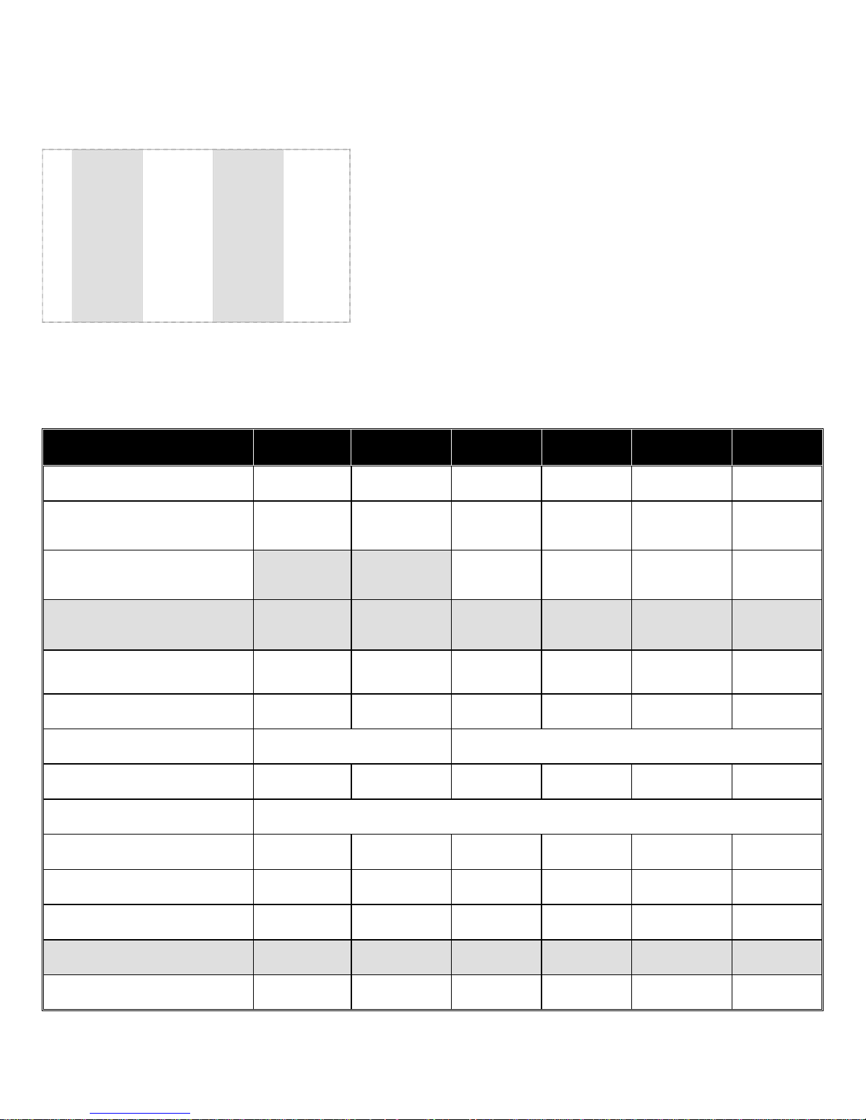
HEADER WAGON SPECIFICATIONS
CHCF25
CHCF30
CHCF36
CHCF42
A
11' 5"
11' 5"
11' 5"
11' 5"
B
3'
3'
3'
3' C 79"
79"
79"
79" D 34' 8"
37' 2"
46' 2"
49' 8"
E
18'
18'
30'
30' F 25'
30'
36'
42' G 37"
67"
31 1/2"
61 1/2"
- 4 -
MODEL CHCF25 CHCF30 CHCF36 CHCF42 CHCFD36 CHCFD42
Rated Capacity 15,500 lb 15,500 lb 15,500 lb 15,500 lb. 15,500 lb 15,500 lb
Tires: 20.5x8-10 12 ply
on 10x6x6 Wheel
Tires: 26x12 12 ply Tubeless Tire
on 12x10.5x6 Wheel
Tires: 11Lx15 12 ply Hwy Service
TL Tire on 15x8x6 HD Wheel
Hubs
Spring Balanced Tongue Standard Standard Standard Standard Standard Standard
Top Rail 4” X 6” HSS Steel Tubing 4” x 6” Bridged Top & Bottom Rail
Standard Standard -------- ------- -------- --------
Optional Optional
Standard Standard Standard Standard
Optional Optional Optional Optional Optional Optional
6 Bolt
Pattern
6 Bolt
Pattern
6 Bolt
Pattern
6 Bolt
Pattern
6 Bolt
Pattern
6 Bolt
Pattern
Max. Head Size 25’ 30’ 36’ 42’ 36’ 42’’
Axle 3” x 6” Structural Welded
Safety Chain Standard Standard Standard Standard Standard Standard
Adjustable Shoes Standard Standard Standard Standard Standard Standard
Tie Down Straps Standard Standard Standard Standard Standard Standard
Road Signal Kit
Optional Optional Optional Optional Optional Optional
Shipping Weight 2030 lb. 2080 lb. 3046 lb. 3120 lb. 3440 lb. 3515 lb.
Page 7

INITIAL OPERATION / MAINTENANCE
WARNING
LUBRICATING THE HEADER WAGON.
WARNING –
BE CERTAIN ALL LIGHTS ARE WORKING PROPERLY BEFORE ENTERING HIGHWAY TRAFFIC.
WARNING
WAGON.
- 5 -
BE CERTAIN ALL POWER IS SHUT OFF BEFORE ADJUSTING, SERVICING, CLEANING OR
BEFORE FIRST USE:
Inspect Wagon for shipping damage. If damage does exist, do not use until damaged parts have been
replaced or repaired.
Ensure slow-moving-vehicle emblem has been properly installed at rear of Wagon.
Ensure all persons operating Wagon have read and understood the operator’s manual.
Properly fasten all braces, bolts, nuts, lug bolts and lug nuts.
Inflate all tires to recommended PSI:
20.5x8-10 12 ply ………………..…..105 PSI MAX (90 PSI recommended for optimum performance)
11Lx15 12 ply …………………..……90 PSI MAX (65 PSI recommended for optimum performance)
26x12 12 ply ………….………………62 PSI MAX (recommended).
Use a high strength hitch pin and chain to fasten Wagon to towing unit.
if equipped with lights
SAFETY CHAIN USER INSTRUCTIONS :
1. Secure safety chain by wrapping it around tongue and feeding it through chain loop located on the
outer side of tongue and connect to the towing unit’s attaching bar.
2. Do not allow more slack than necessary for articulation (max. 9 inches).
3. Do not use any intermediate support as attaching point.
4. Store safety chain by securing it around the tongue.
5. Replace safety chain if one or more links or end fittings are broken, stretched or otherwise damaged
or deformed.
OPERATING INSTRUCTIONS / MAINTANANCE
NEVER POSITION YOURSELF UNDER OR NEAR THE HEADER WHEN MOUNTING HEADER ON
• Adjust brackets on Header Wagon to best fit your make and model header.
• Securely fasten header to Wagon. (refer to pg. 6 - 7)
• After mounting the header on Wagon, turn front wheels to make sure header is positioned clear of tire
movement.
• Absolutely no persons may ride on this equipment.
• Do not exceed load and size limits of the Wagon. Maintain speeds of 20 mph or less.
• Keep tires properly inflated. (Both over inflation and under inflation can greatly reduce tire life.)
• Inspect bracing and welds periodically and repair immediately if needed. Failure to repair could cause extensive
damage and greatly reduce life of Wagon.
• Inspect tie rods and replace bearings in steering assembly when needed.
• Repack bearings in the hub assembly once a year or as needed. Use a good quality bearing lubricant such as
Lithium EP2 or equivalent.
• Check wheel bolts often and keep them properly tightened.
Page 8

BRAKING SYSTEM REQUIREMENTS:
WARNING
TOW LOADS SAFELY.
- 6 -
Stopping distance increases with speed and weight of towed loads and on slopes. Towed loads with or without
brakes that are too heavy for the tractor or are towed too fast can cause loss of control. Consider total weight of
equipment and its load.
Observe these recommended maximum roads speed, or local speed limits which may be lower:
If towed equipment does not have brakes, do not travel more than 32 km/h (20 mph) and do not
tow loads more than 1.5 times the tractor weight.
If towed equipment has brakes, do not travel more than 40 km/h (25 mph) and do not tow loads
more than 4.5 times the tractor weight.
Ensure load does not exceed recommended weight ratio. Use additional caution when towing loads under adverse
surface conditions, when turning and on inclines.
LOADING THE HEADER:
► Tie down brackets can be mounted at any convenient location on back of header. They should line up with
shoes. (These brackets are not required if there are other points on the head to hook the tie down straps.)
► When lowering header on to wagon, front of header should be first to make contact. Adjust top rail accordingly.
Top rail must be positioned squarely under nylon pad at front of header.
Page 9

LOADING THE HEADER (cont.):
- 7 -
► If possible, Grain Header should rest on main beam along bottom rear of header. If header is not equipped with
beam (as in picture) rest on vertical posts/brackets on rear of header.
► For Corn Header, shoe must be turned over and placed directly under rear skid plate on bottom of header.
Page 10
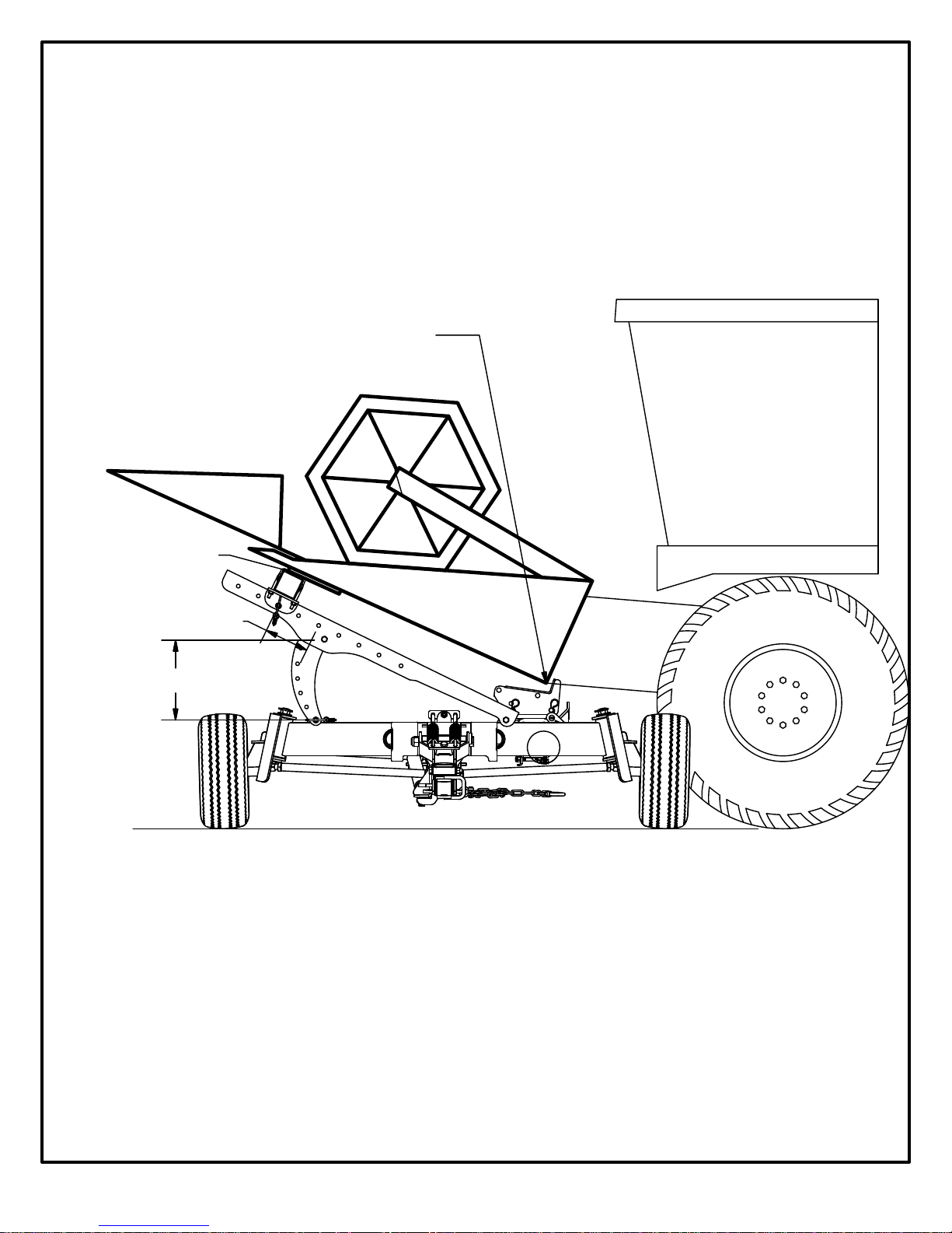
Proper Top Rail Position;
- 8 -
Vertical - Front of header must make contact before heel.
Horizontal - Nylon pads (behind cutter bar) must land
squarely on top of rail. (Grain Header)
Heel should drop 4-6 inches
after front has made contact.
This allows for trouble-
free head hookup.
Must rest on nylon
pad (Grain Header)
Horizontal Adjustment
Vertical Adjustment
Proper Shoe (heel rest) Position;
(Brands & models will differ)
-If header is fitted with a beam along bottom rear, typically
shoes should be positioned close to front and back of wagon.
-If header is NOT fitted with beam along bottom rear, position
shoes so vertical posts on back of header will rest on them.
Front View of Header Wagon
Page 11
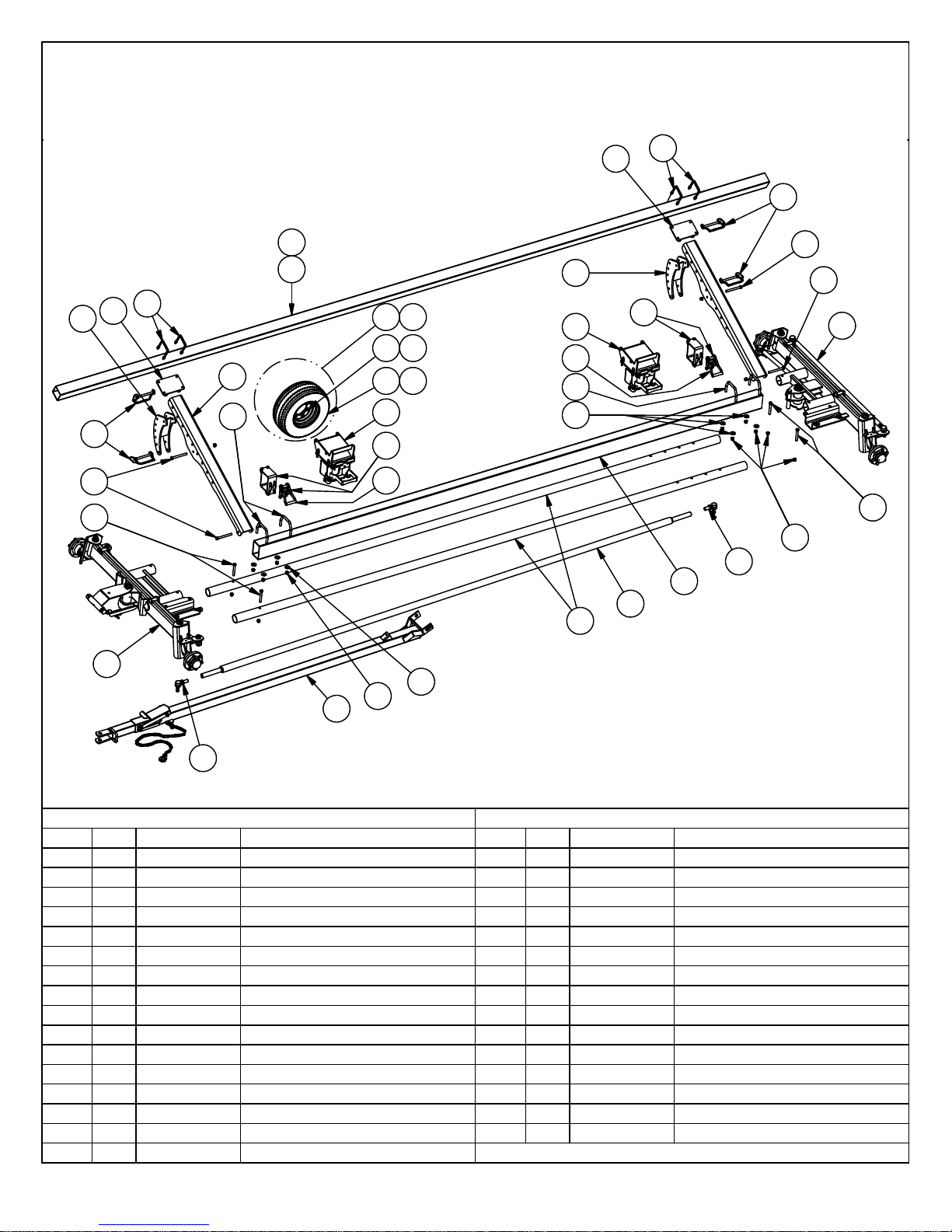
Model
CHCF
CHCF25 & CHCF30 2012 - Current
21
19
25
18
23
22
7
18
17
26
8
11 16
14
12
15
13
4
30
31
21
4
31
26
27
3
7
8
19
19
30
6
25
20
24
1
2
5
10
ITEM
1 1 22-1456
2
32WA-RR18
4 2 22-1454
51
6
7 4 11-1224
8
9
10 1 11-1103
11 4
12
13 1
14 1
15 1
16 1
PART NUMBER
QTY
1
22-1619
WA-FCHCF
1
WA-RCHCF
4
11-1453
1
WA-TCHCF
TI-CHC 20.5 x 8-10 12 PLY TIRE ON 10X6X6 RIM
1
WH-1066 10X6X6 RIM
TI-2058 20.5 X 8 - 10 12PLY TIRE
WH-1586HD 15 X 8 X 6 HD RIM
TI-111512HS 11L x 15 12 PLY HS TIRE
TI-261212121056 26X12 12PLY TIRE ON 12X10.5 X6 RIM
27
20
9
Parts List
DESCRIPTION
Bottom Rail
Joiner Tie Rod Assembly
18ft Reach
Shoe Complete Assembly
CHCF Complete Front Axle
CHCF Complete Rear Axle
U Bolt (1/2 x 4 x 4) & Locknuts
Draw Pin (5/8) c/w Chain & Lynch Pin
CHCF Tongue Assembly
ES176XHD Rod End R Thread
ITEM
17 2 22-1573
18 2 22-1572
19
20 16 11-1026
21 2 22-1574
22
23 1 22-1225
24
25
26 4 11-1439
27 8 11-1440
28
29 4 TI-CHC-11L x 15
30 2 33-1759
31
QTY
4
1
1
4
1
1
PART NUMBER
11-1238
22-1544
11-1104
11-1025
WA-SBD
11-1740
Parts List
DESCRIPTION
Top Rail Support Channel
Top Rail Mount Assembly
5/8 x 6 Bolt & Locknut
5/8 Lock Nut
Top Rail Adjuster Assembly
Top Rail 25' (4" x 4" x .188 HSS)
Top Rail 30' (4" x 4" x .188 HSS)
ES176XHD Rod End L Thread
5/8 x 4 1/2 Hex Bolt & Locknut
5/8 Bottom Rail U-Bolt
5/8 Flat Washer
Double Spring Balancer Assembly
11L x 15 Tire on 6 Bolt Rim
Moveable Ratchet Complete Assembly
Strap Ratchet
Page 12
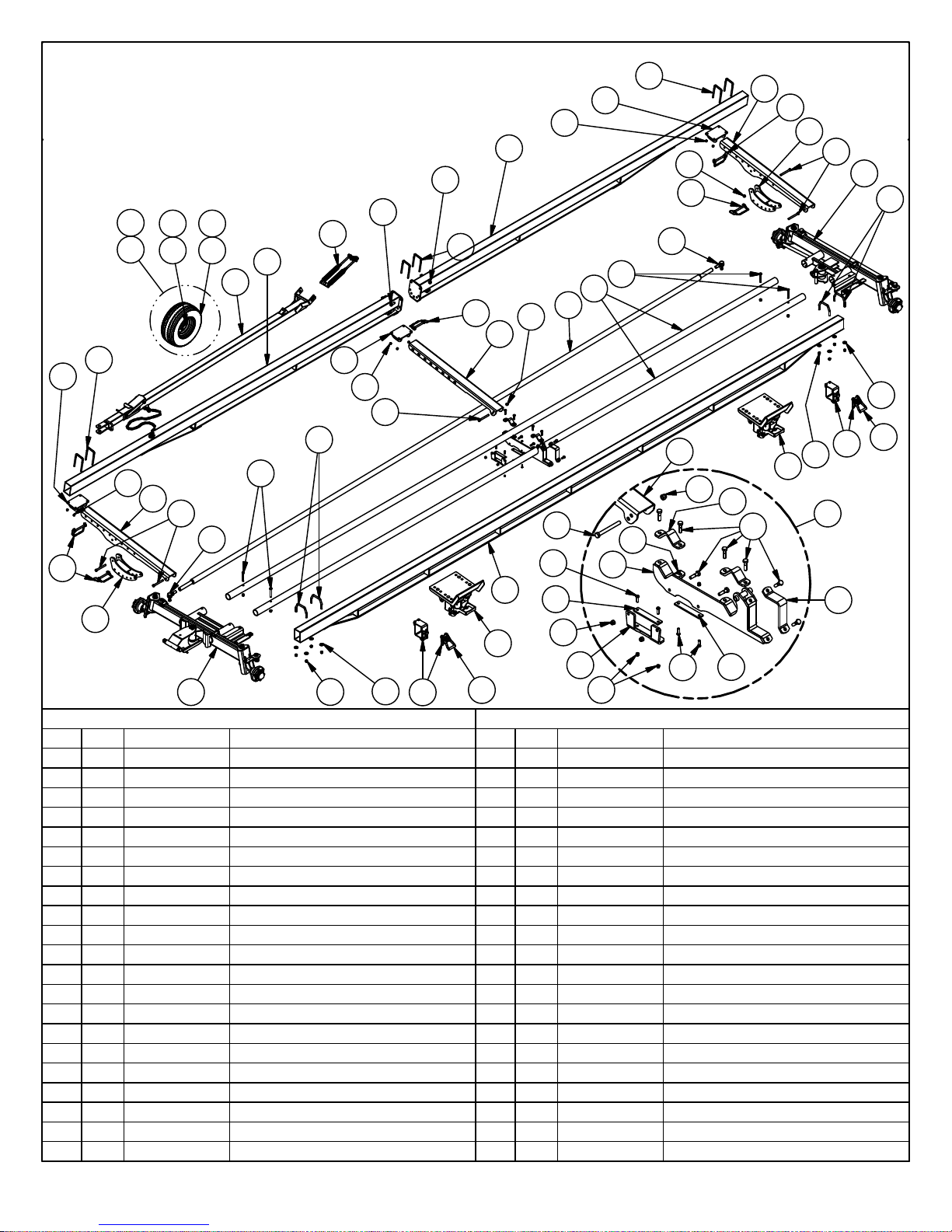
Model
- 10 -
18
9
20
CHCF
CHCF36 & CHCF42
33
423231
34
41
8
28
19
5
3
36
40
8
18
28
17
2
10
30
39
17
18
28
5
6
1
2
7
26
8
1
38
9
24
16
35
13
23
2
5
12
14
28
15
11
21
11
9
4
24
2
12
14
27
29
19
35
9
20
5
37
6
7
13
26
2
25
22
ITEM
1 4
2
3
4 1
5 5
6
7
8
9
10
11
12
13 2
14
15 1 11-1757
16
17
18 3 22-1572
19 2 22-1573
20 2 22-1574
21
PART NUMBER
QTY
11-1025
17
11-1026
1
11-1103
11-1104
11-1238
4
11-1439
11-1440
8
11-1447
6
5
11-1453
7
11-1564
4
11-1584
4
11-1698
11-1740
11-1756
2
1
22-1456D
2 22-1465BRSP
1
22-1592
Parts List
DESCRIPTION
5/8 x 4 1/2 Hex Bolt & Locknut
5/8 Lock Nut
ES176XHD Rod End R Thread
ES176XHD Rod End L Thread
5/8 x 6 Bolt & Locknut
5/8 Bottom Rail U-Bolt
5/8 Flat Washer
U Bolt (.5 x 4 x 6)
Draw Pin (5/8) c/w Chain & Lynch Pin
3/4" Locking nut
3/8" lock nut
3/8 x 1 1/4 Hex Socket Bolt
Strap Ratchet
CHCF Center Support Wear Pad
Joiner Rod Cradle
30' Wheelbase Bottom Rail
36' Bridged Split Top Rail
Top Rail Mount Assembly
Top Rail Support Channel
Top Rail Adjuster Assembly
CHCF Reach Brace Assembly
ITEM
22
23
24
25
26 2 33-1759
27 2 22-1594
28
29
30
31
32
33
34
35 2
36
37
38 2 WA-RR30
39
40
41
42
PART NUMBER
QTY
1
22-1593
1
22-1619L
1
22-1698
1
33-1697
20 LA-SB1022
LA-SB1149
8
7
LA-SS1025
4
TI-111512HS 11LX15 12 PLY HS TIRE
4
TI-2058 20.5X8-10 12 PLY TIRE
4
TI-261212121056 26X12 12 PLY TIRE ON 12X10.5X6 RIM
4
TI-CHC
WA-CHCLPA
1
WA-FCHCF
1
WA-RCHCF
1
WA-SBD
1
WA-TCHCF
4
WH-1066 10X6X6 RIM
4
WH-1586HD 15X8X6 HD RIM
Parts List
DESCRIPTION
6 x 4 Clamp Plate
30' Wheelbase Joiner Tie Rod Assembly
CHCF Center Support Top Rail Link Channel
CHCF Center Reach Support Complete
Moveable Ratchet Complete Assembly
Reach Clamp Plate
1/2" Lock Nut
1/2" x 2" Bolt
3/4 x 2 Hex Bolt
20.5 x 8-10 12 PLY TIRE ON 10X6X6 RIM
Shoe with Large Pad Assembly
CHCF Complete Front Axle
CHCF Complete Rear Axle
30ft Reach
Double Spring Balancer Assembly
CHCF Tongue Assembly
Page 13
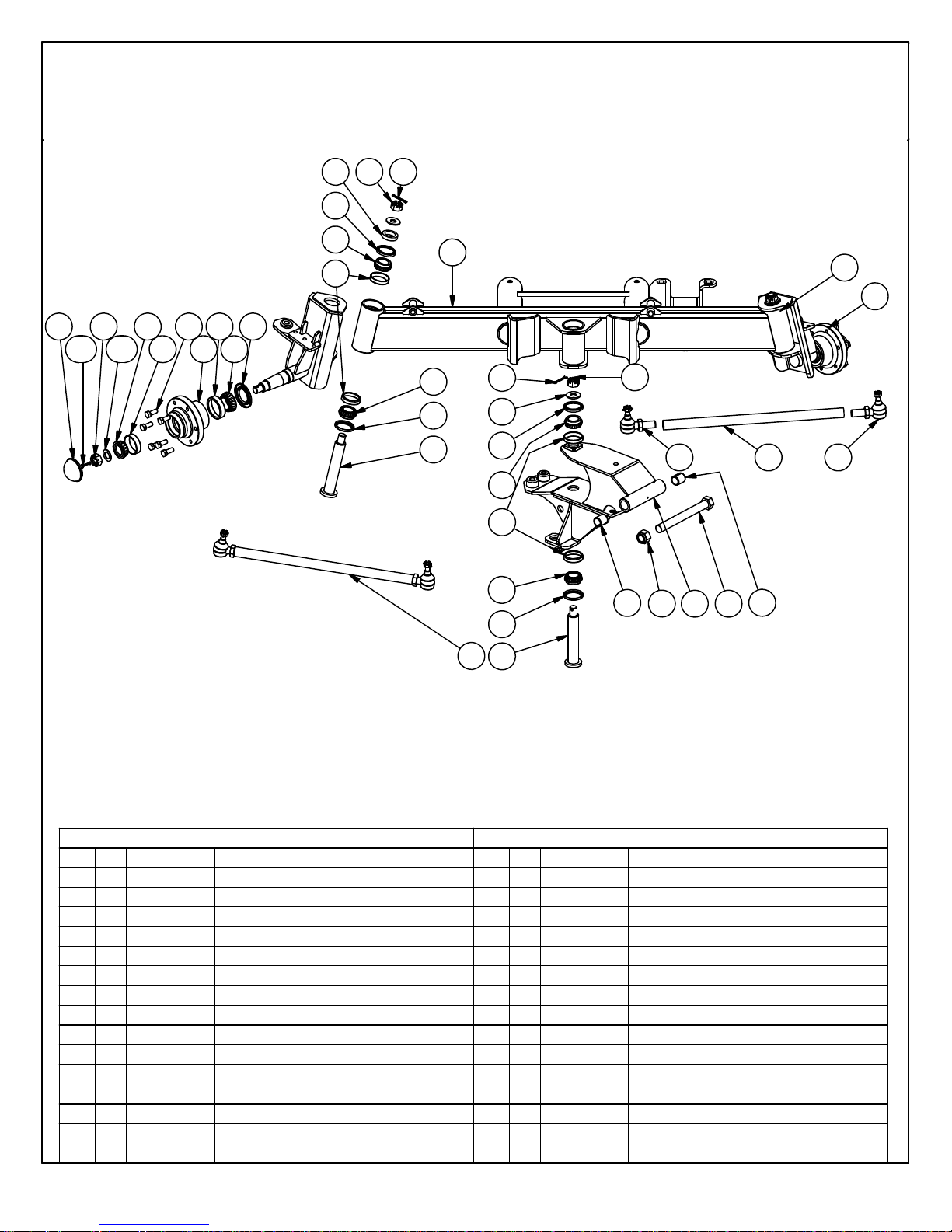
Model
CHCF
WA-FCHCF Front Axle 2012 - Current
10 14 12
6
3.7
3.11
3.9
3.10
3.5
3.2
3.8
3.1
3.3
3.4
3.6
5
4
8
1.6
14
1.5
15
18
1.6
1.4
1
19
12
11
6
5
4
5
6
7
5
6
9
9
3
13
Parts List
ITEM QTY PART NUMBER DESCRIPTION
11
1.4 1
1.5 1 11-1060
1.6 2 11-1054
3 2 33-1072
3.1 1 11-1071
3.2
3.3
3.4 1 11-1074
3.5
3.6
3.7 1
3.8 6 11-1049
3.9
3.10
22-1738
11-1059
1
11-1076
1
11-1075
1
11-1077
1
11-1073
11-1078 Dust Cap (D-6000)
1
11-1051
1 11-1050
Tongue Bracket Assembly (inc. 1.4, 1.5, 1.6)
1-1/8 x 10-3/8 Bolt Gr.2
1-1/8 Lock Nut
Bushing(1-3/8 x 1-1/8 x 1-1/2)
Hub c/w Parts (W-6000)
Hub (W-6000)
[Cup(25821)]
[Cup(25520)]
[Cone(25590)]
[Cone(25877)]
[Seal(CR20148)]
Wheel Bolt (9/16 x 1-3/4)
1" Slotted Hex Nut (1-14)
1" Washer (1-0)
Parts List
ITEM QTY PART NUMBER DESCRIPTION
1
3.11
4
5 6 11-1010
6 6 11-1011
71
8
9 2 22-1441
10 2 22-1529
11 3 11-1014
12 3 11-1016
13 2 11-1103
14 3
15
18 2 22-1737
19 1
11-1016
6 11-1009
22-1055
1 22-1733
11-1081 1" Heavy Hex Slotted Nut
2 11-1104
33-1790 Front Tie Rod c/w Ends
3/16 x 2 Cotter Pin
Cup (13620)
Cone (13686)
Seal (CR20952)
Timkin Bolt
Front Axle Assembly
Spindle Pin Assembly
Spacer Bushing (1.5" ID x 2.25" OD x .5")
3/4 Washer A
3/16 x 2 Cotter Pin
ES176XHD Rod End R Thread
ES176XHD Rod End L Thread
Tie Rod (26")
Page 14
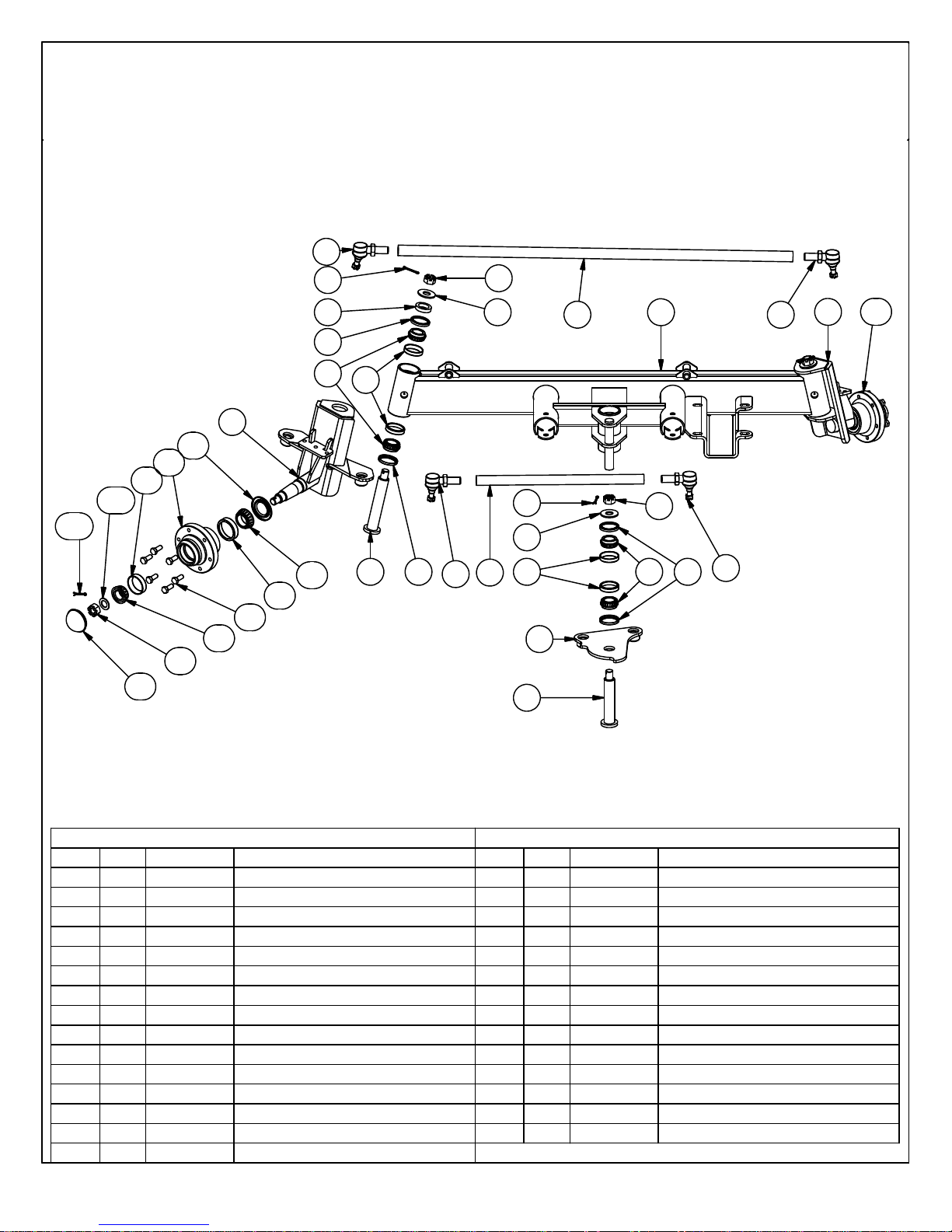
Model
10.11
CHCF
WA-RCHCF Rear Axle 2012 - Current
16
15
12
8
7
6
1
10.6
10.1
10.2
10.10
17
18
15
18
10.1
5
11
17
14
2
10.4
10.3
10.8
10.4
10.9
10.7
Parts List
ITEM QTY PART NUMBER DESCRIPTION
11
2
3 1 22-1625
41
51
6 6 11-1009
7
8 6 11-1011
91
10 2 33-1072
10.1
10.2 1 11-1076
10.3
10.4
10.5 1 11-1077
11-1437
1
11-1548
22-1648
22-1647
6 11-1010
22-1481 Steering Plate Pivot Pin
1
11-1071
1
11-1075
1
11-1074
Steering Spindle Assembly (Right)
Left Rear Spindle Assembly
Rear Axle Steering Plate Assembly
Tie Rod (24") 2007 & Newer
Tie Rod (56.5") 2007 & Newer
Cup (13620)
Cone (13686)
Seal (CR20952)
Hub c/w Parts (W-6000)
Hub (W-6000)
[Cup(25821)]
[Cup(25520)]
[Cone(25590)]
[Cone(25877)]
13 8
6
4
16
3
9
ITEM QTY PART NUMBER DESCRIPTION
10.6
10.7
10.8
10.9
10.10
10.11 1 11-1016
11 1
12 2 22-1529
13 2 22-1441
14
15
16 2 11-1103
17
18 3 11-1376
1
11-1073
1
11-1078
6 11-1049
1
11-1051
1
11-1050
22-1468
2 11-1104
3 11-1016
3 11-1081
7
Parts List
[Seal(CR20148)]
Dust Cap (D-6000)
Wheel Bolt (9/16 x 1-3/4)
1" Slotted Hex Nut (1-14)
1" Washer (1-0)
3/16 x 2 Cotter Pin
Rear Axle Assembly
Spacer Bushing (1.5" ID x 2.25" OD x .5")
Spindle Pin Assembly
ES176XHD Rod End L Thread
3/16 x 2 Cotter Pin
ES176XHD Rod End R Thread
1" Heavy Hex Slotted Nut
1" Washer
14
8
Page 15
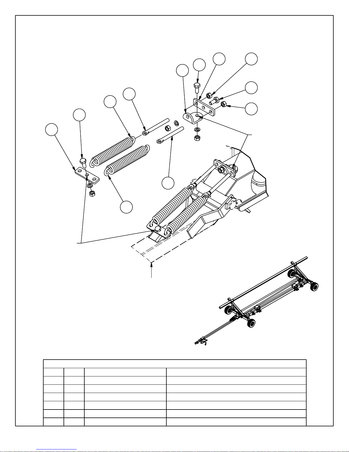
Double Spring Tongue Balancer Kit Included Parts & Assembly Instructions
- 13 -
6 3
5
4
5
1
2
3
5
6
Bolt to Tongue
Bolt to Tongue Bracket
1
2
Lift front of tongue at 45 angle to start eye bolts.
Thread 5/8" nuts on eye bolts (approx. 2" - 3")
until tongue can be lifted effortlessly.
ITEM
1
3
4
5
6
QTY
2
22
5
1
3
11-1516
11-1515
11-1596
22-1513
11-1517
22-15142
PART NUMBER
Parts List
DESCRIPTION
5/8" x 7" Eye Bolt
3/8" Coil x 1-7/8" OD x 12" Extension Spring
5/8 Hex Nut
Spring Balancer Mount
5/8 x 1 1/2 Bolt, Nut & Lockwasher
Double Spring Balancer Plate
Page 16
Model
- 14 -
CHCF
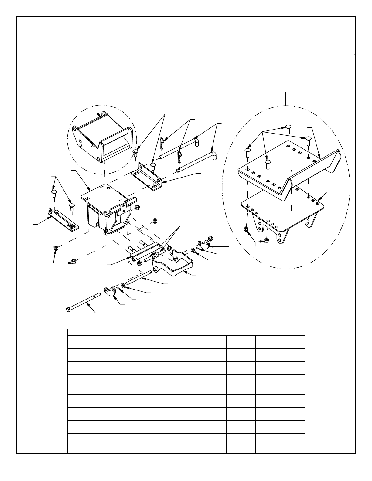
Adjustable Shoe Assembly
For use with "Corn Head",
turn opposite side of
Shoe Riser Pad, up.
(Rotate 180)
70
67
69
Optional Draper Head Shoe
68
67
72
62
28
67
59
73
61
27
65
63
64
Quantities are per Wagon (not per assembly)
REF. # CHC PART # DESCRIPTION
27
28 11-1026
59
60 22-1457
61 22-1458
62
63 22-1459
64 22-1460
65 11-1461
66 11-1462
67
68 22-1464
69
70 22-1483
71
72
73 22-1595
11-1440
33-1482
22-1211
11-1463
11-1445
22-1570
22-1571
5/8 Flat Washer
5/8 Lock Nut
Shoe Pad 2 2
Shoe Lock Handle 2 2
Handle Pivot Pin
Shoe Pad Angle
Clamp Linkage Plate
Bolt (5/8 x 9-1/2)
Roll Pin (3/16 x 1-1/8)
Bolt (5/8 x 2)
Carriage Bolt (5/8 x 1-1/2)
Shoe Heal Pin
Hitch Pin (480-009)
Shoe Riser Pad 2
Draper Shoe Riser
Draper Shoe Pad
Clamp Adjustment Weldment
66
60
62
27
63
65
QTY.
4 4
18 26
2 2
4 4
4 4
2 2
4 4
4 4
8
4 4
4 4
N/A
N/A
2 2
71
28
QTY. (Draper)
24
N/A
2
2
Page 17
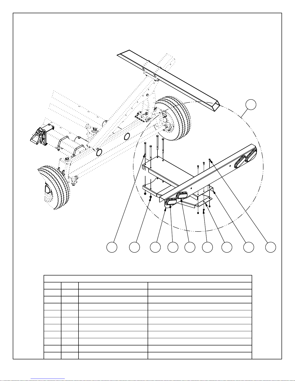
Wagon Light Kit (optional)
- 15 -
1
ITEM
1.2
1.3
1.4
1.5
1.6
1.7
QTY
11.1
1
1
4
4
WA-LK11
22-1585
22-1587
22-1586
11-1583
11-15843
LA-SB1022
11-10213
11-170821.8
11-170721.9
PART NUMBER
1.6
Parts List
1.8 1.9
DESCRIPTION
Light Bracket Complete Assembly
Light BracketTop Plate
Light Bracket Bar
Light Bracket Bottom Brace
1/2" x 7 1/2" UNC Hex Bolt
3/8" Locknut
1/2" Lock Nut
3/8" x 1" Bolt & Lock Washer
Amber Oval Light
Red Oval Light
1.5
1.31.2
1.1 1.71.4
Page 18
WAGONS
1-866-567-4162 www.horstwelding.com 8082 Rd 129 Listowel, ON , N4W 3G8, Canada
- 16 -
HORST
Horst Welding Warranty Policy
All equipment is sold subject to mutual agreement that it is warranted by the
company to be free from defects of material and workmanship. But the
company shall not be liable for special, indirect, or consequential damages
of any kind under this contract or otherwise.
limited exclusively to replacing or repairing without charge, at its factory or
elsewhere, at its discretion, any material or workmanship defects that
become apparent within one year from the date on which the equipment
was purchased. The company shall have no liability for related damages of
any kind. The buyer by the acceptance of the equipment will assume all
liability for any damages that may result from the use or misuse by his
employees or others.
Distributor/dealer must notify Horst Welding of the defect by phone, fax or
email. Recommended repairs and cost are to be discussed with, and
agreed on, by an authorized Horst Welding representative. Repair and labor
(at an agreed rate) will be performed by a dealer for Horst Welding or a
repair shop designated by Horst Welding.
All claims must be discussed with a representative of Horst Welding prior to
any repairs or warranty will be void.
All claims must be acco m panied by a photograph of the d efective product.
All defective products must be returned to Horst Welding in Listowel, Ontario
unless directed otherwi se by a representative of Ho rst Welding.
Horst Welding Warranty will not apply to:
• Product that in the judgment of Horst Welding has been misused by
the user.
• Product not sold or manufactured by Horst Welding.
• Alterations or repairs not authorized by a representative of
Welding.
The company’s liability shall be
Horst
 Loading...