

Page 1
ZZOONNEEPPLLUUSS FF222288mm // FF222288ee
IINNSSTTAALLLLAATTIIOONN AANNDD
CCOOMMMMIISSSSIIOONNIINNGG IINNSSTTRRUUCCTTIIOONNSS
LEAFLET No P82412
ISSUE 1
PPaaggee 44
Email: sales@horstmann.co.uk
Website: www.horstmann.co.uk
The F228m / F228e valve with auxiliary switch has been designed
to control the water circulation in fully pumped systems, which
employs a single pump for both Hot water and Central heating
circuits, by allowing the flow to either or both circuits using
separate valves.
Horstmann Controls Limited
Bristol
BS4 1UP
t:0117 9788 773 - f:0117 9788 701
MMoottoorr ssuuppppllyy vvoollttaaggee::
230V AC, 50Hz
PPoowweerr ccoonnssuummppttiioonn::
<6.5W
LLeeaadd ssuupppplliieedd::
1 metre 6 core cable. Industry standard colours used
EEaarrtthh ccoonnnneeccttiioonn rreeqquuiirreedd..
OOlliivvee SSiizzee::
F228m - 28
mm (Metric)
F228e- 1
1/4
inch (Imperial)
OOppeerraattiinngg ffllooww tteemmppeerraattuurree::
Up to 80oC
SSwwiittcchh rraattiinngg::
5 Amps
MMaaxxiimmuumm aammbbiieenntt tteemmppeerraattuurree::
50
o
C
MMaaxxiimmuumm ssttaattiicc pprreessssuurree::
21 Bar
MMaaxxiimmuumm ddiiffffeerreennttiiaall pprreessssuurree::
2 Bar
PPiippee ffiittttiinngg ssiizzee::
22
mm compression
AAccttuuaattoorr::
Maximum time to power open - 20 seconds
Maximum time to spring close - 10 seconds
OOvveerrrriiddee lleevveerr::
For manual operating to open valve for system draining or filling.
During normal operation, the lever must be in the auto position.
SPECIFICATION
PPaaggee 11
INSTALLATION AND CONNECTION SHOULD ONLY BE CARRIED OUT BY A SUITABLY QUALIFIED
PERSON AND IN ACCORDANCE WITH THE CURRENT EDITION OF THE I.E.E. WIRING
REGULATIONS. A CLASS ‘A’ SWITCH (HAVING CONTACT SEPARATION OF AT LEAST 3MM IN
ALL POLES) MUST BE INCORPORATED IN THE FIXED WIRING AS A MEANS OF DISCONNECTING
THE SUPPLY, NORMALLY AT THE CONSUMER UNIT. THE SYSTEM MUST BE APPROPRIATELY
FUSED.
WWAARRNNIINNGG :: IISSOOLLAATTEE MMAAIINNSS SSUUPPPPLLYY BBEEFFOORREE CCOOMMMMEENNCCIINNGG IINNSSTTAALLLLAATTIIOONN
COMMISSIONING
To check whether the valve is operating correctly, carry out the following checks after the system is filled and vented. Ensure that the override lever is in the Auto position and the insert
guide is removed.
FFOORR GGRRAAVVIITTYY SSYYSSTTEEMMSS::
HHOOTT WWAATTEERR OONNLLYY..
Set the room thermostat to minimum or turn the CH off at the programmer.
Set the cylinder thermostat to maximum and turn the HW on at the programmer.
The valve should be open and the boiler only should fire.
CCEENNTTRRAALL HHEEAATTIINNGG OONNLLYY..
Set the cylinder thermostat to minimum or turn the HW off at the programmer.
Set the room thermostat to maximum and turn the CH on at the programmer.
The valve should remain closed but the boiler should fire and the pump should run.
HHOOTT WWAATTEERR AANNDD CCEENNTTRRAALL HHEEAATTIINNGG..
Set the room and cylinder thermostat to maximum and turn the HW and CH on at the
programmer.
The valve should be open. The boiler should fire, pump run and the pipes on the Port B should
get hot.
FFOORR AA FFUULLLLYY PPUUMMPPEEDD SSYYSSTTEEMM::
IIff tthhee vvaallvvee iiss ffiitttteedd oonn aa HHWW cciirrccuuiitt..
Set the cylinder thermostat to maximum or turn the HW on at the programmer. The valve
should open. The boiler should fire, the pump run and the pipe on the Port B side should get
hot.
IIff tthhee vvaallvvee iiss ffiitttteedd oonn aa CCHH cciirrccuuiitt..
Set the room thermostat to maximum or turn the CH on at the programmer. The valve should
open. The boiler should fire, the pump run and the pipe on the Port B side should get hot.
Reset both thermostats and the programmer to their normal settings.
PPlleeaassee nnoottee
the above assumes that both programmer and thermostats are being used. If this
is not the case, ignore the action described for the item not fitted.
Page 2
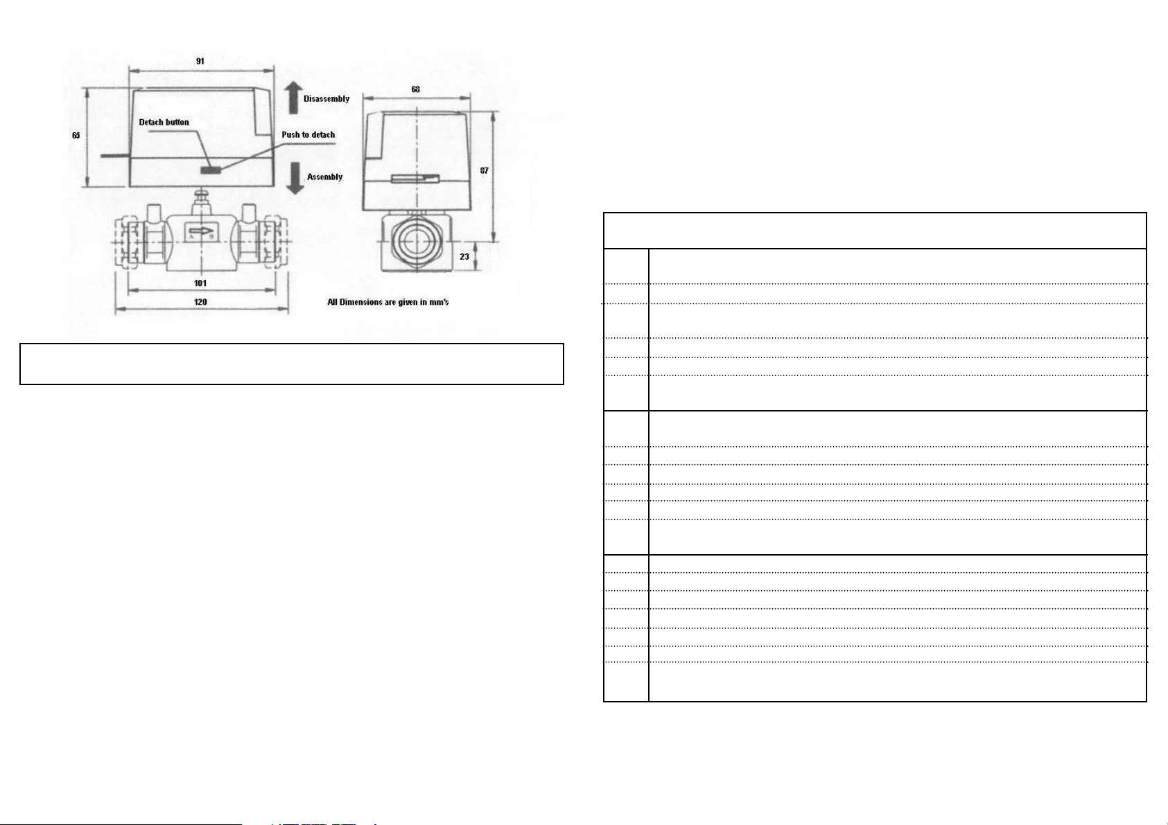
Fit the valve body using the compression fittings provided.
Tighten the compression nuts sufficiently to make a watertight seal, only gripping the valve
by its body.
TTaakkee ccaarree nnoott ttoo oovveerr ttiigghhtteenn..
INSTALLATION AND OPERATING INSTRUCTIONS
POSITIONING OF VALVE
On new installations fit the valve ensuring that the actuator head is NOT below the
horizontal level of the pipework and that flow is in the direction of the arrow. Also check that
neither the open vent or the cold feed are isolated. This will ensure system and product
safety at all times.
Remember to make allowances for working, maintenance and replacement.
FITTING OF VALVE BODY TO PIPEWORK
PPLLEEAASSEE NNOOTTEE;; BBeeffoorree bbeeggiinnnniinngg tthhee iinnssttaallllaattiioonn,, oorr aannyy ssuubbsseeqquueenntt rreemmoovvaall ooff tthhee aaccttuuaattoorr,,
pplleeaassee eennssuurree tthhaatt tthhee oovveerrrriiddee lleevveerr,, llooccaatteedd oonn tthhee ssiiddee ooff tthhee aaccttuuaattoorr iiss iinn tthhee rraaiisseedd
bbyyppaassss ppoossiittiioonn..
Position the actuator on the valve body, taking care to line up the 4
mm flat spindle, located
on the valve body, with the receiving shaped slot located on the underneath of the actuator.
The actuator guide holes should line up with the spigot on the valve body.
The actuator locking mechanism will click into place, locking the head to the valve body.
WIRING CONNECTIONS
The 6 core cable fitted to the actuator can now be connected to the system following the
simple colour-coded guide below.
An earth connection is required on the F228m and F228e valve. Ensure all connections are
good and the screw secure. A torque of 0.75Nm is recommended for fixing the wires in place.
NNOOTTEE::
In the event that the F228m or F228e is being used in an unconventional system, the
above connections may be incorrect. In this case, please seek advice.
FITTING OR REMOVAL OF ACTUATOR TO VALVE BODY
PPaaggee 33
Valve position - In the event that mains power is disconnected the valve automatically
spring-returns to the closed position (Port A).
PPaaggee 22
OPERATION
Set the override lever to manual. Fill, test and thoroughly flush the system (See instruction
under the Specification section located on page 4 of this guide).
To remove the Actuator from the valve body please ensure that the override lever is placed
in the override position.
WWiirree CCoolloouurr SSyysstteemm CCoonnnneeccttiioonn
FFOORR AA GGRRAAVVIITTYY HHWW SSYYSSTTEEMM::
Blue Any Neutral supply.
Brown ‘Call’ terminal of cylinder stat if fitted, otherwise the HW on terminal of the programmer.
White Live terminal on pump and ‘Call’ terminal of room stat if fitted, otherwise the CH on
terminal of the programmer.
Orange Live terminal on boiler
Grey Any permanent live supply
.
Yellow/ Earth terminal or the wiring centre
Green
FFOORR AA FFUULLLLYY PPUUMMPPEEDD SSYYSSTTEEMM AANNDD FFIITTTTEEDD TTOO TTHHEE HHWW CCIIRRCCUUIITT::
Blue Any Neutral supply.
Brown ‘Call’ terminal of cylinder stat if fitted, otherwise the HW on terminal of the programmer.
White Not used. Make electrically safe.
Orange Live terminal of pump and boiler
Grey Any permanent live supply.
Yellow/ Earth terminal or the wiring centre
Green
FFOORR AA FFUULLLLYY PPUUMMPPEEDD SSYYSSTTEEMM AANNDD FFIITTTTEEDD TTOO TTHHEE CCHH CCIIRRCCUUIITT::
Blue Any Neutral supply.
Brown ‘Call’ terminal of room stat if fitted, otherwise the CH on terminal of the programmer.
White Not used. Make electrically safe.
Orange Live terminal of pump and boiler
Grey Any permanent live supply.
Yellow/ Earth terminal or the wiring centre
Green
 Loading...