

Page 1

COMMISSIONING
To check whether the valve is operating correctly, carry out the following checks after the system is
filled and vented. Ensure that the override lever is back in the Auto position and the insert guide is
removed.
HOTWATERONLY.
Set the room thermostat to minimum or turn the CH off at the programmer.
Set the cylinder thermostat to maximum and turn the HW on at the programmer.
The valve should close Port A. The boiler should fire, pump run and the pipe on the Port B side should
get hot.
CENTRALHEATINGONLY.
Set the cylinder thermostat to minimum or turn the HW off at the programmer.
Set the room thermostat to maximum and turn the CH on at the programmer.
The valve should close Port B. The boiler should fire, pump run and the pipe on the Port A side should
get hot.
APPLICATION
The Z322XL mid-position valve has been designed to control
the water circulation in fully pumped systems, which employs
a single pump for both Hot water and Central heating circuits,
by diverting the flow to either circuit or both simultaneously
using a single valve.
HOTWATERANDCENTRALHEATING.
Set the room and cylinder thermostat to maximum and turn the HW and CH on at the programmer.
The valve should be in the mid-position. The boiler should fire, pump run and the pipes on both Port A
side and Port B should get hot.
Reset both thermostats and the programmer to their normal settings.
Please notethe above assumes that both programmer and thermostats are being used. If this is not
the case, ignore the action described for the item not fitted.
SPARES
The actuator and body for the Z322XL mid-position valve can be purchased separately as spares or as
replacement parts(see page 1).
Email: sales@horstmann.co.uk
Website: www.horstmann.co.uk
Page 4
Horstmann Controls Limited
Bristol
BS4 1UP
t:0117 9788 773 - f:0117 9788 701
LEAFLET No P80955
ISSUE 2
INSTALLATION AND CONNECTION SHOULD ONLY BE CARRIED OUT BY A SUITABLY QUALIFIED PERSON
AND IN ACCORDANCE WITH THE CURRENT EDITION OF THE IEE WIRING REGULATIONS.
A CLASS ‘A’ SWITCH (HAVING CONTACT SEPARATION OF AT LEAST 3MM IN ALL POLES) MUST BE
INCORPORATED IN THE FIXED WIRING AS A MEANS OF DISCONNECTING THE SUPPLY, NORMALLY AT THE
CONSUMER UNIT. THE SYSTEM MUST BE APPROPRIATELY FUSED.
WARNING:ISOLATE MAINS SUPPLY BEFORE COMMENCING INSTALLATION
SPECIFICATION
Motor supply voltage: 230V AC, 50Hz
Power consumption:<6W
Lead supplied:1 meter 4 core cable. Industry standard colours used
No earth connection required as unit is double insulated
Operating flow temperature:-5
Switch rating:3Amps
Maximum ambient temperature:50
Maximum static pressure:8.6 Bar
Maximum differential pressure: 0.5 Bar
Pipe fitting size:22mm compression
Actuator:Maximum time to power
open - 20 seconds
Maximum time to spring
close - 10 seconds
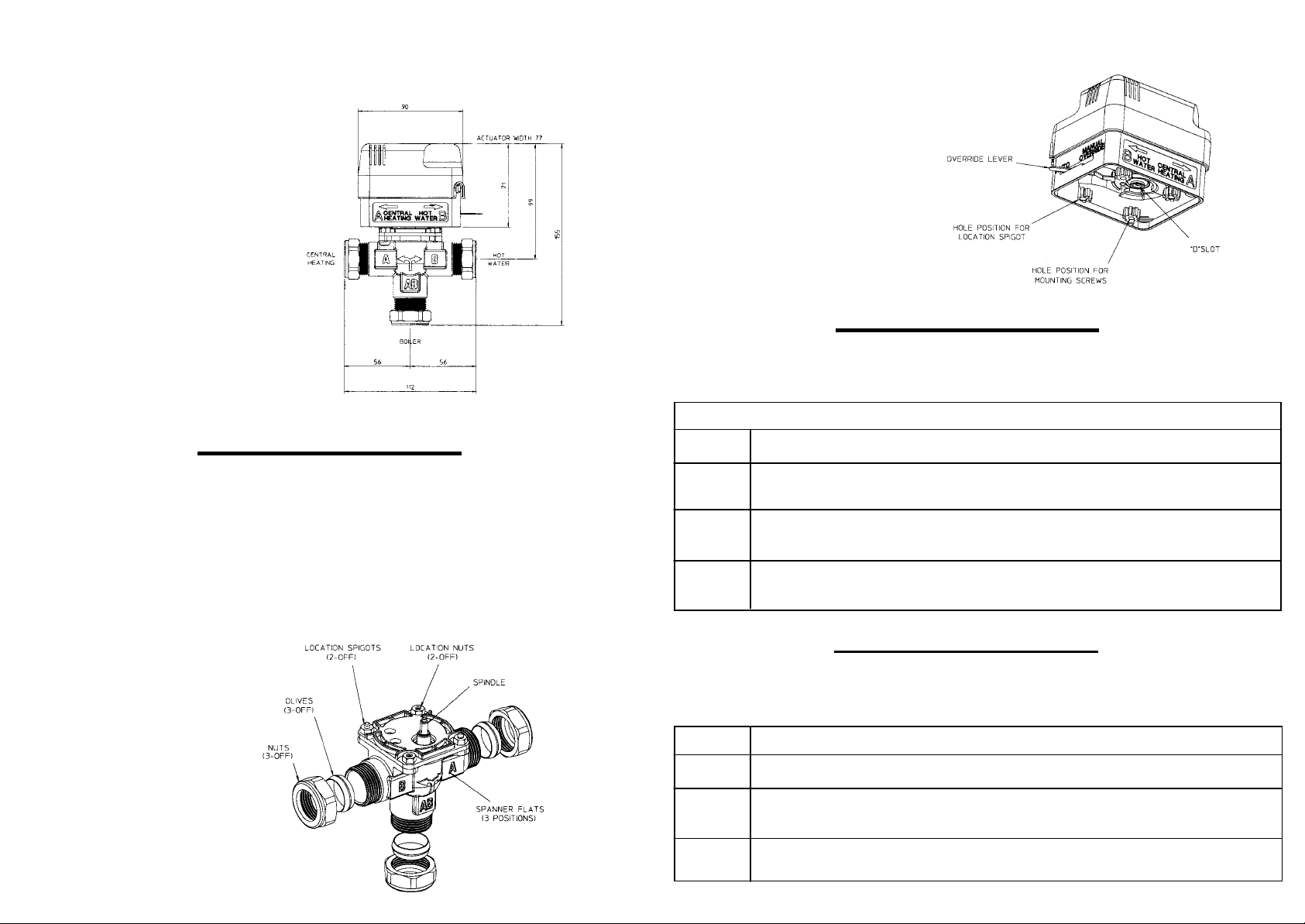
Override lever:For manual operating to
mid-position for system draining or filling.
During normal operation, the lever must be
in the auto position.
(See diagram opposite).
The Z322XL consists of a 3 port valve body (Ref.B322XL) to
which a self-contained actuator (Ref.A322XL) is attached.
o
C to 88oC
o
C
A322XL - ACTUATOR
B322XL - BODY
Page 1
Page 2
Valve position - In the event that mains
power is disconnected the valve
automatically spring-returns to the Hot
water only position.
Position of valve during the various
operation:
HW only - Port A closed
OPERATION
FIT ACTUATOR TO VALVE BODY
Position the actuator on the valve body
lining up the valve spindle with the ‘D’
shape slot. A yellow guide strip has been
inserted behind the Override lever to
assist installation,please remove the
guide once the actuator installation is
complete and before the system is used.
The actuator guide holes should line up
with the spigots on the valve body.
HW & CH - Valve in position AB (Middle)
CH only - Port B closed
The Valve operates both boiler and
pump when either Heating or Hot water
is required.
INSTALLATION
POSITIONING OF VALVE
On new installations ensure that the Z322XL valve is fitted on the flow from the boiler only. Also check
that the actuator head is NOTbelow the horizontal level of the pipework and that neither the open
vent nor the cold feed are isolated. This will ensure system and product safety at all times.
Remember to make allowances for working, maintenance and replacement.
FITTING OF VALVE BODY TO PIPEWORK
Fit the valve body using the
22mm compression fittings
provided with the flow from
the boiler to AB, the radiator
circuit to Port A, and the Hot
water cylinder to Port B.
Tighten the compression nuts
sufficiently to make a
watertight seal, only gripping
the valve by its body.
Take care not to over tighten.
Fix with the screws provided and tighten
lightly. The override lever should now be
on the Port B side.
Set the override lever to manual. Fill, test and thoroughly flush the system (see diagram and
instruction under the Specification section located on page 4 of this guide).
WIRING CONNECTIONS- STANDARD INSTALLATION
The 4 core cable fitted to the actuator can now be connected to the system following the simple
colour-coded guide below.
Wire Colour System Connection
Blue Any Neutral supply.
Orange ‘Call’ terminal of Cylinder Stat if fitted, otherwise the ‘HW ON’ terminal of
the programmer - Also link to Pump/Boiler live.
White ‘Call’ terminal of room Stat if fitted, otherwise the ‘CHON’ terminal of
programmer.
Grey ‘Stat’ terminal of Cylinder Stat if fitted, otherwise the ‘HW OFF’ terminal of
the programmer.
No earth connection is required. Ensure all connections are good and the screw secure. A torque of
0.75Nm is recommended for fixing the wires in place.
USING A ZONEPLUS Z322XL AS A DIVERTER VALVE
The following connections will enable the Z322XL to act as a diverter valve, giving priority to the
Central heating.
Wire Colour System Connection
Blue Any Neutral supply.
Orange ‘Call’ terminal of Cylinder Stat if fitted, otherwise the ‘HW ON’ terminal of
the programmer - Also link to Pump/Boiler live.
Page 2
White+Grey ‘Call’ terminal of room Stat if fitted, otherwise the ‘CHON’ terminal of
programmer.
Page 3
 Loading...