

horsch SW 12000 SD Operating Instructions Manual
Operating Instructions
Art.: 80790201 en
Read carefully prior to starting up!
Keep operating instructions in a safe place!
07/2011
SW 12000 SD

EC Declaration of Conformity
In accordance with EC Directive 2006/42/EC
We, HORSCH Maschinen GmbH
Sitzenhof 1
D-92421 Schwandorf
do solely declare that the product
HORSCH SW 12000 SD
which is the subject of this declaration, fully conforms with the pertinent safety and health requi-
rements specied in EC Directive 2006/42/EC.
The following harmonised standards and technical specications were applied for correct interpretation of the safety and health requirements specied in the EC Directive:
DIN EN ISO 12100 Safety of machines
DIN EN 14018 Safety of drills
Schwandorf, 11.05.2010 Person responsible for documentation:
Place and Date Gerhard Muck
____________________ ____________________
M. Horsch P. Horsch
(Managing Director) (Development and Construction)

Operating instructions: 07/2011 80790201 SW 12000 SD en
I hereby conrm receipt of the operating instructions for the above mentioned machine.
I have been instructed by a HORSCH service technician or authorised dealer in the operation and
functions of the machine, as well as in the safety requirements.
........................................................................
Name of the service technician
Machine Registration
No warranty claims will be accepted if this machine registration form is
not returned !
I am aware that a warranty claim will only be valid if this form has been fully completed, signed and
returned to HORSCH Maschinen GmbH, or has been given to the Service Technician, immediately
after rst instruction.
................................................................... ........................................................................
Place, date of rst instruction Buyer’s signature
Dealer
Name: ............................................................
Street: ............................................................
Postal code: ...................................................
Place: .............................................................
Tel.: ................................................................
Fax:.................................................................
E-mail: ...........................................................
Customer No. : ...............................................
Customer
Name: ............................................................
Street: ............................................................
Postal code: ...................................................
Place: .............................................................
Tel.: ................................................................
Fax:.................................................................
E-mail: ...........................................................
Customer No. : ...............................................
.
Type of machine: ............................................
Serial number: ................................................
Delivery date: .................................................
To
HORSCH Maschinen GmbH
Postfach 10 38
D-92401 Schwandorf
Fax: +49 (0) 9431 / 41364
Demonstration machine – initial use
Demonstration machine - relocation
Demonstration machine nal sale - use
New machine nal sale – initial use
Customer‘s machine - relocation


- Translation of the Original Operating Instructions -
Machine Identication
The corresponding data is to be entered into the list below upon
receiving the machine:
Serial number: ..................................................
Machine type: ...................................................
Year of construction: ........................................
Initial installation: ..............................................
Fittings: .............................................................
..........................................................................
..........................................................................
..........................................................................
Publication date of Operation Manual: 07/2011
Latest change:
Address of Retailer: Name: ......................................................................
Road: ......................................................................
Town/City: ......................................................................
Tel.: ......................................................................
Customer No.:
Retailer: ......................................................................
Address of HORSCH: HORSCH Maschinen GmbH
92421 Schwandorf, Sitzenhof 1
92401 Schwandorf, Postbox 1038
Tel.: +49 (0) 9431 / 7143-0
Fax: +49 (0) 9431 / 41364
E-mail: info@horsch.com
Customer No.:
HORSCH: ......................................................................

2
Table of contents
Introduction .................................................4
Foreword ......................................................4
Warranty claims ............................................4
Intended use .................................................5
Consequential damage ...............................5
Authorised operators ....................................6
Protective clothing ........................................6
Information regarding safety .....................7
Safety symbols .............................................7
Operational safety ........................................9
Road trac safety.........................................9
Accident prevention .................................... 10
Hitching / un-hitching ................................10
Hydraulic connections ..............................10
Pressure accumulator .............................10
Changing implements ............................... 11
In operation ...............................................11
Service and maintenance ........................... 11
Technical data ...........................................12
Execution ................................................12
Dimensions and weights .........................12
Hydraulic coupling ..................................12
Tractor power required ...........................12
Tyres .......................................................12
Lighting .....................................................13
Hydraulic system ........................................14
Transport / installation .............................15
Delivery.......................................................15
Machines with DrillManager ME ...............15
Installation ..................................................15
Hitching and unhitching the machine..........16
Connect the hydraulic system ..................17
Connecting the road lighting equipment ...17
Parking the machine ................................. 17
Setting / Operation ...................................18
Seed and fertiliser hopper ..........................18
Venturi area ................................................ 19
Fan .............................................................19
Pneumatic system .................................... 21
Halfside shut-down (option) ...................... 24
Placing seeds with both hoppers .............. 24
Re-tightening the fan impeller ...................25
Metering unit ............................................. 26
Roller change ...........................................27
Roller change with full hopper ................. 27
Checking the sealing lip ............................28
Roller for ne seeds ..................................28
Rape brushes ........................................... 30
Coarse seeds ...........................................31
Metering unit with Venturi-type injector ....31
Servicing the metering unit .......................32
Checks .......................................................33
Work instructions ........................................ 35
Filling auger ..............................................36
Brake system ............................................38
Hydraulic brake .........................................40
Service and maintenance ........................41
Cleaning .....................................................41
Maintenance intervals.................................41
Preparation for storage ...............................41
Lubricating the machine ...........................42
Hygiene ...................................................42
Handling of lubricants ............................. 42
Service........................................................42
Maintenance schedule................................43
Lubrication points .....................................44
Possible faults - remedy .............................45

3

4
Introduction
Foreword
Before operating the machine, read and strictly
comply with the operating instructions. In doing
so, you will avoid accidents, reduce repair costs
and downtime and increase the reliability and
service life of your machine. Pay attention to
the safety instructions!
HORSCH will not assume liability for any damage or malfunctions resulting from failure to
comply with the operating instructions.
These operating instructions will assist you in
getting to know your machine and in using it
correctly for its intended purposes. First you are
given general instructions in handling the ma-
chine. This is followed by chapters on servicing,
maintenance and the action to be taken should
a malfunction occur.
The operating instructions must be read and
strictly adhered to by all persons working on or
with the machine e.g.
¾ Operation (including preparation, fault recti-
cation during work and servicing)
¾ Maintenance (maintenance and inspection)
¾ Transport
Together with the operating instructions, you
also receive receipt. Field service technicians
will instruct you in the operation and care of
your machine. After this you should return the
machine registration form to HORSCH.
This conrms your formal acceptance receipt
of the machine. The warranty period starts with
the date of delivery.
We reserve the right to alter illustrations as well
as technical data and weights contained in these
operating instructions for the purpose of improv-
ing the machine.
Warranty claims
Warranty claim forms must be submitted through
your local HORSCH dealer to the HORSCH
Service Department in Schwandorf.
Only claims, which have been correctly completed and submitted no later than four weeks
after the defect occurred, can be processed.
Exchange parts, which require the old part to be
returned, are marked with the letter "R".
Please return these components cleaned and
emptied to HORSCH within 4 weeks together
with a warranty claim form and precise fault
description.
Exchange parts, which do not require the old
part to be returned. Please keep such parts for
12 weeks, until a decision has been made on
the action to be taken.
Warranty repairs, which are to be carried out by
a third-party company, or which are expected
to take longer than 10 working hours, must be
agreed upon in advance with the Customer
Service Department.

5
Intended use
The seed wagon is state-of-the-art and designed in accordance with relevant, recognised
safety regulations. However, risks of injury to
the operator or third parties and impairment of
the machine or other tangible assets can occur
during use.
The machine must only be operated for its intended use if in a technically perfect condition,
whilst being aware of safety and risks and in
strict compliance with the operating instructions!
Faults, particularly those which impair safety,
must be remedied immediately.
The machine must only be operated, serviced
and repaired by persons who are familiar with
it and have been made aware of the dangers
involved.
Genuine spare parts and accessories from
HORSCH have been specially designed for this
machine. Spare parts and accessories which
are not delivered by us, have not been tested
or approved by us.
Installation or use of non-original HORSCH
products may have a detrimental effect on
specic design features of the machine and
impair the safety of machine operators and the
machine itself.
HORSCH will not assume liability whatsoever for
damage resulting from the use of non-original
parts and accessories.
The machine is designed to distribute seeds
and fertilisers. Any other use beyond these
limits, e.g. as a means of transport, is deemed
improper.
HORSCH will not assume liability whatsoever
for damage resulting from unintended use. The
risk will be borne solely by the user.
The respective accident prevention regulations
and other generally recognised safety-related,
occupational medical and road trac regulations
are to be adhered to.
Intended use also includes the strict compliance
with the operating instructions and adherence to
the operating, maintenance and repair instruc-
tions specied by the manufacturer.
Consequential damage
The mac hine has bee n manufactured by
HORSCH with great care. Nevertheless, even
when used properly, deviations or complete
failure in the application rate may be caused,
e.g. by:
¾ dierences in the composition of seed or
fertiliser (i.e. grain size distribution, density,
geometrical shape, dressing, sealing).
¾ blockages or seed bridging (i.e. caused by
foreign bodies, non-smooth seeds, sticky
dressing, moist fertiliser).
¾ Worn wearing parts (e.g. metering unit).
¾ Damage caused by external inuences.
¾ incorrect drive motor speeds and driving
speeds.
¾ incorrect setting of the unit (incorrect connec-
tion, non-observance of setting tables).
Therefore, it is crucial to always check your
machine before and during operation for correct
operation and adequate application accuracy.
Compensation claims for damages which have
not been caused by the machine, are excluded.
This also includes that any liability for consequential damages caused by drill and control
commands, is excluded.
6
In these operating instructions
The operating instructions distinguish between
three dierent types of warning and safety instructions. The following graphic symbols are
used:
important instructions!
if there is a risk of injury!
if there is a risk to life and limb!
It is important that all the safety instructions
contained in these operating instructions and
all the warning signs on the machine are read
thoroughly
Ensure that the warning signs are legible and
replace signs that are missing or damaged.
These instructions must be followed in order
to prevent accidents. Inform other users of the
warnings and safety instructions.
Do not carry out any operations which may aect
the safe use of the machine.
Authorised operators
Only those persons who have been authorised
and instructed by the operator may operate the
machine. Operators must be at least 16 years
of age.
The operator must hold a valid driving licence.
He is responsible for third parties in the operat-
ing area.
The person in charge must
¾ make the operating instructions available to
the operator.
¾ Ensure that the operator has read and under-
stood the operating instructions.
The operating instructions are a component part
of the machine.
Protective clothing
For operation and maintenance you need:
¾ snug tting clothing.
¾ protective gloves to protect against sharp-
edged machine parts.
¾ protective goggles to protect the eyes against
dust or spray, when working with fertiliser or
liquid fertiliser. Strictly observe the handling
instructions given by the fertiliser manufac-
turer.
¾ when handling dressing or dressed seed
wear a respirator mask and protective gloves.
Strictly observe the handling instructions
given by the dressing manufacturer.
7
Information regarding
safety
The following warnings and safety instructions
apply to all sections in these operating instruc-
tions.
Safety symbols
On the machine
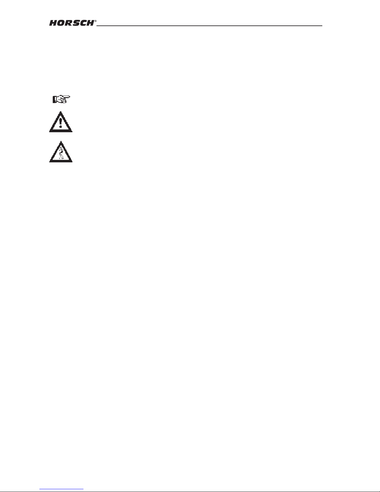
Retighten the wheel nuts / wheel bolts after 50
km or 10 hours. Tighten every day - see maintenance overview.
Watch out for uids spraying out
under high pressure, follow the
operating instructions
00380133
Never reach into areas where there
is a risk of crushing, as long as parts
could still be moving!
00380134
No passengers are allowed to ride
on the machine!
00380054
Read and adhere to the operating
instructions before starting up the
machine!
00380055
In order to prevent eye injuries, do
not look directly at the beam area
when the radar sensor is switched
on!
00380894
Switch the engine o and pull out
the key before starting maintenance
and repair work.
00380294
The return ow pressure at the fan drive must
not exceed 5 bar, as otherwise the hydraulic
motor may be destroyed.
00380242
max. 5 bar
00380359
8
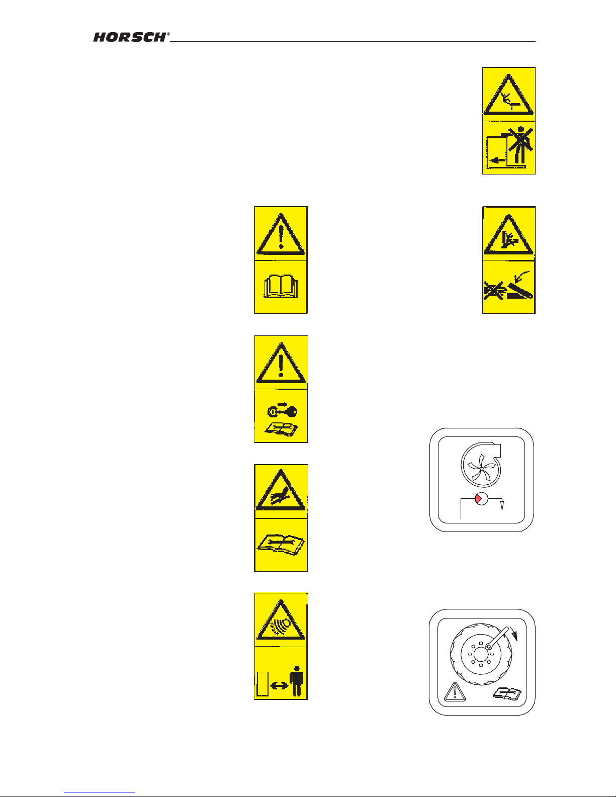
Lifting hook; attach lifting tackle (chains, ropes,
etc.) here when performing loading work.
Attach the scales here when calibrating.
00380880
00380879
OFF
ON
ZERO
HZ
SZ
HK
SK
B
A
R1
R2
L1
L2
Z1
Z2
00384071
Connection of hydraulic couplings
00384068
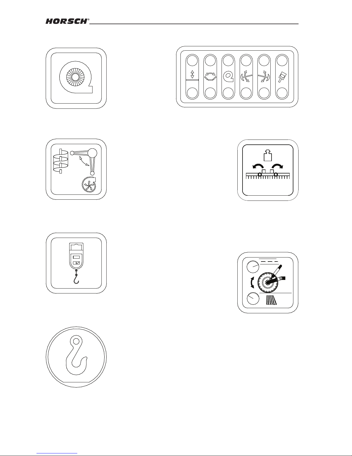
Pressure display for fan drive
00380882
Changeover fan drive / lling auger
For uniform weight distribution load the outer
wings with max. 70 kg
00384072
0
bar
0
bar
The hydraulic circuit "Packer" must only be under pressure during road travel
In the eld it should not be under pressure switch to oating position.
00384070
max. 70 bar
kg
9
Operational safety
The machine must only be put into operation
after receiving instructions by employees of the
authorized dealer or a HORSCH employee. The
machine registration form has to be completed
and returned to HORSCH.
All protective features and safety equipment,
such as detachable protective devices, must be
correctly in place and reliably functioning before
the machine is put into operation.
¾ Check and tighten nuts and screws at regular
intervals.
¾ Check tyre pressure regularly.
¾ In case of malfunctions stop and secure the
machine immediately!
Road trafc safety
The valid road trac regulations are to be observed when travelling on public roads, paths
and areas.
Do not exceed the max. permissible widths
and attach light system, warning and protective
devices.
Also observe transport height depending on the
coupled machine!
Do not exceed the permissible axle loads, tyre
carrying capacities and total weights, in order
to ensure sucient steering and braking capabilities. Handling is aected by the connected
equipment. It is important to take into account
the large overhang and the centrifugal mass of
the implement, particularly when cornering.
Clean all soil o the machine before driving on
public roads.
Passengers are strictly forbidden to ride on the
machine!
On public roads travel at a maximum speed
of 25 km/h and only with am empty seed
hopper.
00110681 00110682
00110687
00110687
00110687
00110681 00110682
00110683 00110684
00110687
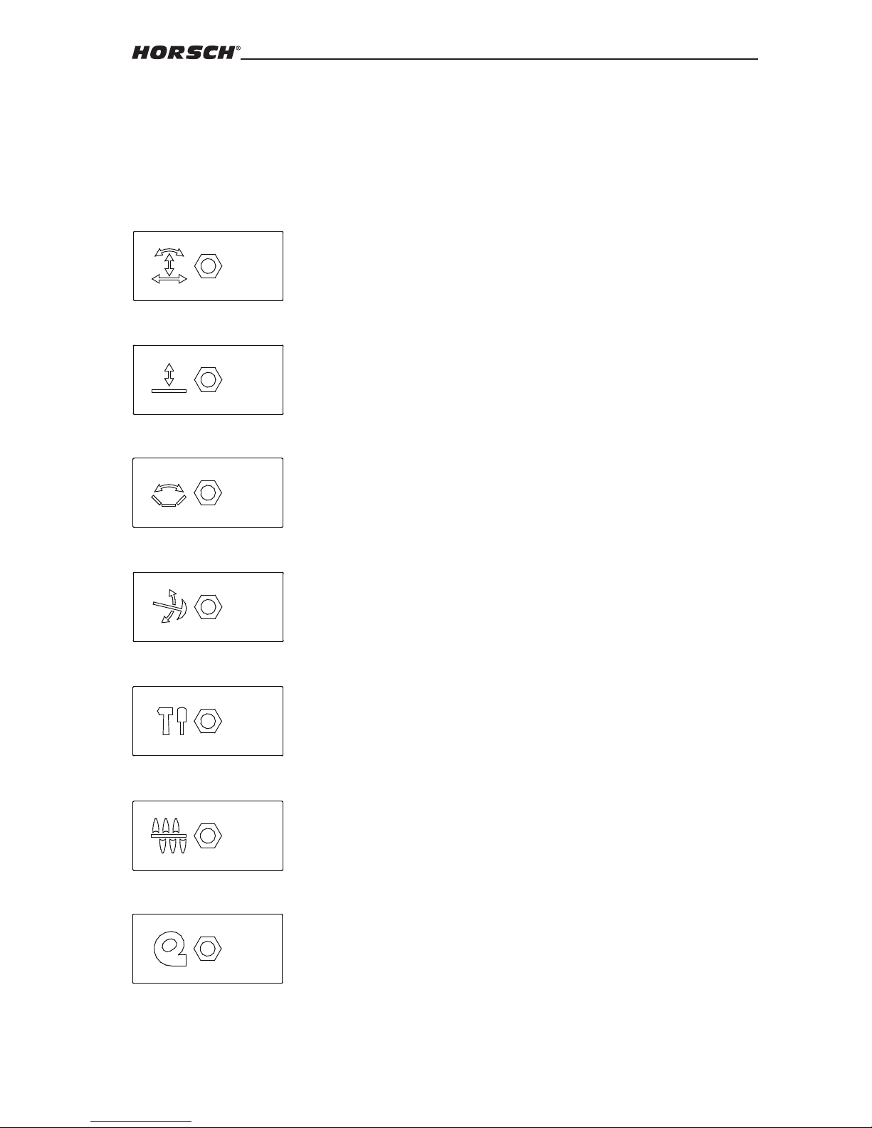
Hydraulic valve block
Filling auger
Machine up / down
Unfold / fold machine
Tools
Bout markers
Fan
Identication marks on hydraulic hoses
The symbol is always found on the hose requiring pressure to bring the machine to transport
position (raising, folding, etc.).

10
Hydraulic connections
¾ Do not connect hydraulic lines to the tractor,
before both hydraulic systems (machine and
tractor) are de-pressurised.
¾ The hydraulic system is under high pressure.
Check all lines, hoses and screwed con-
nections regularly for leaks and any visible
external damage!
¾ Only use appropriate aids when checking for
leaks. Repair any damage immediately! Oil
sprays can cause injuries and re!
¾ In the case of injury, contact a doctor im-
mediately!
Power sockets and connectors on the hydraulic
connections between the tractor and machine
should be colour-coded in order to exclude op-
erating errors.
The control unit on the tractor must
be secured or locked when not in use
or when the machine is in transport
position, in order to prevent accidents
caused by unintended hydraulic movements or movements caused by persons other than the operator (children,
passengers).
Pressure accumulator
Ending on the hitched up drill a pressure ac-
cumulator may be installed.
Do not open or work (welding, drilling) on the
pressure accumulator. Even after being emptied, the accumulator is still preloaded by gas
pressure.
Always de-pressurize the pressure accumulator
before starting work on the hydraulic system.
The pressure gauge should not indicate any
pressure.
The pressure gauge reading should drop to 0
bar. Only then may work be carried out on the
hydraulic system.
Accident prevention
In addition to the operating instructions, it is
important to observe the accident prevention
regulations specied by agricultural trade associations!
Hitching / un-hitching
There is risk of injury to persons when hitching/
un-hitching the machine to the drawbar of the
tractor.
¾ Secure the machine against rolling away.
¾ Take special care when reversing the tractor.
Never stand between tractor and machine.
¾ Only park the machine on a rm and level
surface. Before un-hitching the machine,
lower it to the ground.

11
Service and maintenance
¾ Ensure that regular tests and inspections are
always carried out to schedule, as specied
in the operating instructions.
¾ Prior to performing maintenance and servicing
work, ensure that the machine is positioned
on rm, level ground and that it is properly
secured against rolling away.
¾ De-pressurise the hydraulic system and lower
or support the implement.
¾ Before cleaning the machine with high pres-
sure cleaning equipment cover all openings,
which should stay clear of water, steam or
cleaning agents for reasons of safety or op-
eration. Do not aim the water jet directly at
electrical or electronic components, bearings
or the fan.
¾ After cleaning, check all hydraulic lines for
leaks and loose connections.
¾ Check hoses for chang and signs of other
damage. Remedy any faults immediately!
¾ Prior to working on the electrical system,
disconnect it from the electric power supply.
¾ When performing welding work on the ma-
chine, disconnect the cables from computers
and other electronic components. The ground
connection must be as close as possible to
the welding point.
¾ Re-tighten screwed connections which have
been loosened during servicing and mainte-
nance work.
Do not wash new machines with a
steam-jet or high-pressure cleaner. The
paint takes approx. 3 months to cure
and could thus be damaged if this time
has not yet expired.
Changing implements
¾ Secure the machine against unintended roll-
ing!
¾ Secure lifted frame parts, under which you will
be working, with suitable supports!
In operation
¾ Check the area around the machine (for chil-
dren!) before setting o and starting operation
of the machine. Ensure sucient visibility.
¾ Do not remove any of the mandatory and
supplied protective devices.
¾ Stay clear of the operating range of hydrauli-
cally operated parts.
¾ Only use ascending aids and steps when ma-
chine is at standstill. Passengers are not allowed to ride on the machine during operation!

12
Technical data
Execution
Drill control: ..................................... electronic
Metering unit drive: .......................... electronic
Metering quantity: ....................... 0 - 500 kg/ha
Hydraulic fan:...........................max 5.000 rpm
Dimensions and weights
Width:
Version SW with wheels 650/65 R 38: ....3.00 m
Version SW with wheels 900/60 R 37: ....3.35 m
Version NT
with twin tyres: 20.8 R 42 ....................4.30 m
Version NT with wheels 650/65 R 38: ..3.55 m
Height:
Version SW:..........................................3.68 m
Version SW with lling auger: ...............3.93 m
Version SW lling height:......................3.34 m
Version NT:...........................................3.73 m
Version SW with lling auger: ...............3.98 m
Version SW lling height:......................3.39 m
Length:
Version SW:..........................................7.40 m
Version NT:.........................................6.880 m
Weight:
Version SW with lling auger: ............ 4.450 kg
Axle load: ........................................... 3.500 kg
Tongue load:......................................... 950 kg
Seed hopper capacity: .......................... 6,000 l
Fertiliser hopper capacity: ....................6,000 l
Hydraulic coupling
1 x double acting: .......................Control block
1 x double acting with
ow control valve: ......................................Fan
1 x freeow return: ................................leak oil
Tractor power required
Hydraulic pressure: .............................180 bar
required oil quantity: ...........................45 - 85 l
Tyres
Version SW / NT .......................... 650/65 R 38
Version SW / NT .......................... 900/60 R 37
Version NT with twin tyres ............... 20.8 R 42
K 80
3000
3680 ohne Befüllschnecke
1230
7139,2
2243
3340Einfüllhöhe
3930
1560
Version SW
580/70 R38
1020
6770
3980
3390Einfüllhöhe
4x 20.8 R 42
4286
Version NT
 Loading...