

horsch Pronto 7 DC, Pronto 8 DC, Pronto 9 DC, Pronto 8 PPF Operating Instructions Manual
Operating Instructions
Art.: 80200202 en
Read carefully prior to starting up!
Keep operating instructions in a safe place!
Specialists in modern
cultivation and seeding technology
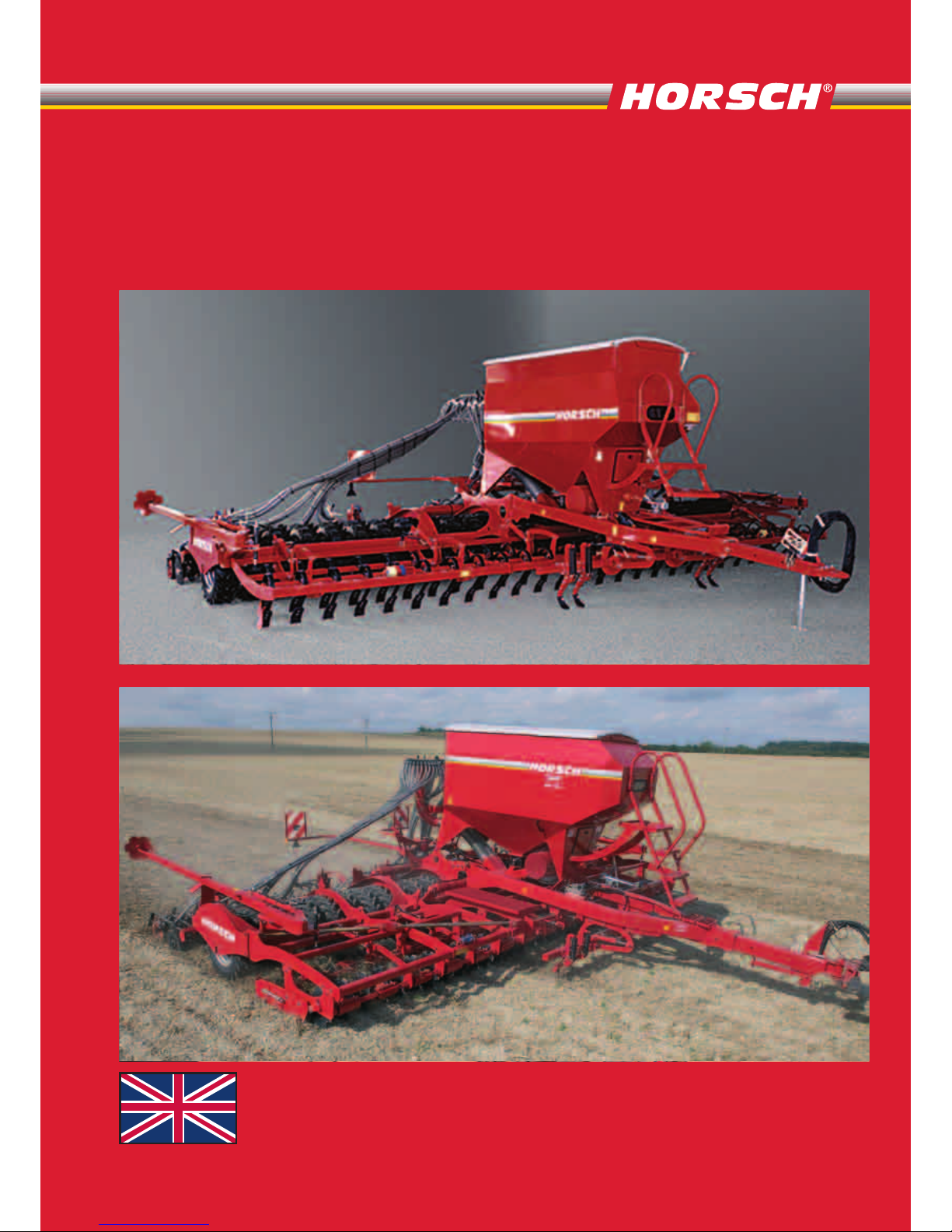
HORSCH Pronto
HORSCH Pronto
7 / 8 / 9 DC 8 PPF
7 / 8 / 9 DC 8 PPF
«»
396336, .,
-, .
, .
7.
( 4 «» 519 –
)
./ 8 (473) 233-28-17
E-mail: info@texagropark36.ru
texagropark.ru

EC Declaration of Conformity
In accordance with EC Directive 98/37/EC
We, HORSCH Maschinen GmbH
Sitzenhof 1
D-92421 Schwandorf
do solely declare that the product
HORSCH Pronto 7 DC from Serial No. 23771251
8 DC 23781282
9 DC 23791277
8 PPF 23881250
which is the subject of this declaration, fully conforms with the pertinent safety and health require-
ments specied in EC Directive 98/37/EC.
The following harmonised standards and technical specications were applied for correct interpretation of the safety and health requirements specied in the EC Directive:
DIN EN ISO 12100 - 1
DIN EN ISO 12100 - 2
Schwandorf, 12.06.2007
Place and Date
____________________ ____________________
M. Horsch P. Horsch
(Managing Director) (Development and Construction)

Please detach and send to HORSCH Maschinen GmbH or give to the service technician when receiving instruction
Operating instructions: 02/2009 80200202 Pronto 7 - 9 DC / 8 PPF en
I hereby conrm receipt of the operating instructions and spare parts list for the above mentioned
machine.
I have been instructed by a HORSCH service technician or authorised dealer in the operation and
functions of the machine, as well as in the safety requirements.
........................................................................
Name of the service technician
Machine Registration
No warranty claims will be accepted if this machine registration form is
not returned !
I am aware that a warranty claim will only be valid if this form has been fully completed, signed and
returned to HORSCH Maschinen GmbH, or has been given to the Service Technician, immediately
after rst instruction.
................................................................... ........................................................................
Place, date of rst instruction Buyer’s signature
Dealer
Name: ............................................................
Street: ............................................................
Postal code: ...................................................
Place: .............................................................
Tel.: ................................................................
Fax:.................................................................
E-mail: ...........................................................
Customer No. : ...............................................
Customer
Name: ............................................................
Street: ............................................................
Postal code: ...................................................
Place: .............................................................
Tel.: ................................................................
Fax:.................................................................
E-mail: ...........................................................
Customer No. : ...............................................
Type of machine: ............................................
Serial number: ................................................
Delivery date: .................................................
To
SIMBA International Ltd.
Woodbridge Road
GB-Sleaford, Lincolnshire NG34 7EW
Fax: +44 (0) 1529 / 413101
For customers out of Great Britain,
return it to your local dealer!
Demonstration machine – initial use
Demonstration machine - relocation
Demonstration machine nal sale - use
New machine nal sale – initial use
Customer‘s machine - relocation


- Translation of the Original Operating Instructions -
Machine Identication
The corresponding data is to be entered into the list below upon
receiving the machine:
Serial number: ................................................
Machine type: ................................................
Year of construction: ......................................
Initial installation: ............................................
Optional extras: ..............................................
..........................................................................
..........................................................................
..........................................................................
Publication date of Operation Manual: 02/2009
Address of Retailer: Name: ......................................................................
Road: ......................................................................
Town/City: ......................................................................
Tel.: ......................................................................
Customer No.:
Retailer: ......................................................................
Address of HORSCH: HORSCH Maschinen GmbH
92421 Schwandorf, Sitzenhof 1
92401 Schwandorf, Postbox 1038
Tel.: +49 (0) 9431 / 7143-0
Fax: +49 (0) 9431 / 41364
E-mail: info@horsch.com
Customer No.:
HORSCH: ......................................................................

6
Table of contents
Introduction .................................................8
Foreword ......................................................8
Warranty claims ............................................8
Intended use .................................................9
Consequential damage ...............................9
Authorised operators ..................................10
Protective clothing ......................................10
Information regarding safety ................... 11
Safety symbols ...........................................11
Operational safety ......................................15
Road trac safety.......................................15
Accident prevention .................................... 15
Hitching up / unhitching ............................ 15
Changing implements ............................... 16
In operation ...............................................16
Service and maintenance ........................... 17
Transport/Installation ...............................18
Delivery.......................................................18
Machines with DrillManager ME ...............18
Installation ..................................................18
Install DrillManager ................................... 19
Adjusting the bout markers ....................... 20
Technical data ...........................................21
Pronto 7 DC ................................................21
Pronto 8 DC ................................................21
Pronto 9 DC ................................................22
Pronto 8 PPF .............................................. 22
Road lighting equipment .............................23
Hydraulic system Pronto 7/8/9 DC .............24
Hydraulic system Pronto 7/8/9 DC
with front packer .........................................25
Hydraulics Pronto 8 DC PPF ...................... 26
Brake system ..............................................27
Pneumatic brake .......................................27
Hydraulic brake .........................................28
Hitching-up the machine .............................30
Connecting the hydraulic system ..............30
Connecting the road lighting equipment ...30
Hydraulic function .....................................31
Unfold / fold machine ..................................31
Parking the machine ...................................32
Operation ...................................................33
Pneumatics Pronto DC ............................... 33
Fan ...........................................................33
Fan direct drive ........................................ 34
Fan with PTO-shaft driven pump .............. 35
Re-tightening the fan impeller ...................37
Hopper 7/8/9 DC.........................................38
Hopper 8 PPF .............................................38
Venturi-type injector....................................38
Half side shut-down ..................................38
Twin hoppers 8 PPF for 2 x seed ...........39
Distribution box seed and fertiliser .............41
Hose arrangement .................................... 42
Metering unit ...............................................43
Roller change ...........................................44
Roller change with full hopper ................. 44
Checking the sealing lip ............................45
Roller for ne seeds ..................................45
Rape brushes ........................................... 47
Coarse seeds ...........................................48
Metering unit with Venturi-type injector ...48
Servicing the metering unit .......................49
Seeding component....................................50
Rear Harrow .............................................52
Calibration ..................................................53
Setting ......................................................53
Drill depth ...................................................53
Prework tools ..............................................55
Work instructions ........................................ 57
Checks........................................................58
Additional Fittings ......................................60
Pre emergency markers ...........................60
Hydr. coulter pressure adjustment ............61
Track Eradicators .....................................61
Filling Auger ..............................................62
Service and maintenance ........................63
Cleaning .....................................................63
Maintenance intervals.................................63
Preparation for storage ...............................63
Lubricating the machine ...........................64
Hygiene ...................................................64
Handling of lubricants ............................. 64
Service........................................................64
Maintenance schedule................................65
Lubrication points .....................................67
Bolt tightening torques - metric bolts ..........69
Bolt tightening torques - imperial bolts .......70

7

8
Introduction
Foreword
Before operating the machine read and strictly
comply with the operating instructions. In doing
so, you will avoid accidents, reduce repair costs
and downtime and increase the reliability and
service life to your machine. Pay attention to
the safety instructions!
HORSCH will not assume liability for any damage or malfunctions resulting from failure to
comply with the operating instructions.
These operating instructions will assist you in
getting to know your machine and in using it
correctly for its intended purposes.
The operating instructions must be read and
strictly adhered to by all persons working on or
with the machine e.g.:
¾ operation (including preparation, fault recti-
cation during work and servicing)
¾ maintenance (maintenance and inspection)
¾ Transport
Together with the operating instructions, you
also receive a spare parts list and a machine
registration form. Field service technicians
will instruct you in the operation and care of
your machine. After this you should return the
machine registration form to HORSCH. This
conrms your formal acceptance receipt of the
machine. The warranty period starts with the
date of delivery.
We reserve the right for alter illustrations as
well as technical data and weights contained in
these operating instructions for the purpose of
improving the machine.
Warranty claims
Warranty claim forms must be submitted through
your local HORSCH dealer to the HORSCH
Service Department in Schwandorf.
Only claims, which have been correctly com-
pleted and submitted no later than four weeks
after the defect occurred, can be processed.
Exchange parts, which require the old part to be
returned, are marked with the letter "R".
Please return these components cleaned and
emptied to HORSCH within 4 weeks together
with a warranty claim form and precise fault
description.
Exchange parts, which do not require the old
part to be returned. Please keep such parts for
12 weeks, until a decision has been made on
the action to be taken.
Warranty repairs, which are to be carried out by
a third-party company, or which are expected
to take longer than 10 working hours, must be
agreed upon in advance with the Customer
Service Department.

9
Intended use
The drill is state-of-the-art and designed in accordance with relevant, recognised safety regu-
lations. However, risks of injury to the operator
or third parties and impairment of the machine
or other tangible assets can occur during use.
The machine must only be operated for its intended use if in a technically perfect condition,
whilst being aware of safety and risks and in
strict compliance with the operating instructions!
Faults, particularly those which impair safety,
must be remedied immediately.
The machine must only be operated, serviced
and repaired by persons who are familiar with
it and have been made aware of the dangers
involved.
Genuine spare parts and accessories from
HORSCH have been specially designed for this
machine. Spare parts and accessories which
are not delivered by us, have not been tested
or approved by us.
Installation or use of non-original HORSCH
products may have a detrimental effect on
specic design features of the machine and
impair the safety of machine operators and the
machine itself.
HORSCH will not assume liability whatsoever for
damage resulting from the use of non-original
parts and accessories.
The machine is designed to distribute seeds
and fertilisers. Any other use beyond these
limits, e.g. as a means of transport, is deemed
improper.
HORSCH will not assume liability whatsoever
fro damage resulting from unintended use. The
risk will be borne solely by the user.
The respective accident prevention regulations
and other generally recognised safety-related,
occupational medical and road trac regulations
are to be adhered to.
Intended use also includes the strict compliance
with the operating instructions and adherence to
the operating, maintenance and repair instruc-
tions specied by the manufacturer.
Consequential damage
The mac hine has bee n manufactured by
HORSCH with great care. Nevertheless, even
when used properly, deviations or complete
failure in the application rate may be caused,
e.g. by:
¾ dierences in the composition of seed or
fertiliser (i.e. grain size distribution, density,
geometrical shape, dressing, sealing).
¾ blockages or seed bridging (i.e. caused by
foreign bodies, non-smooth seeds, sticky
dressing, moist fertiliser).
¾ Worn wearing parts (e.g. metering unit).
¾ Damage caused by external inuences.
¾ incorrect drive motor speeds and driving
speeds.
¾ incorrect setting of the unit (incorrect connec-
tion, non-observance of setting tables).
Therefore, it is crucial to always check your
machine before and during operation for correct
operation and adequate application accuracy.
Compensation claims for damages which have
not been caused by the machine, are excluded.
This also includes that any liability for consequential damages caused by drill and control
commands, is excluded.

10
In these operating instructions
The operating instructions distinguish between
three dierent types of warning and safety instructions. The following graphic symbols are
used:
important instructions.
if there is a risk of injury!
if there is a risk to life and limb!
It is important that all the safety instructions
contained in these operating instructions and
all the warning signs on the machine are read
thoroughly
Ensure that the warning signs are in a legible
and replace and signs that are missing or damaged.
These instructions must be followed in order
to prevent accidents. Inform other users of the
warnings and safety instructions.
Do not carry out any operations which may aect
the safe use of the machine.
Authorised operators
Only those persons who have been authorised
and instructed by the operator may operate the
machine. Operators must be at least 16 years
of age.
The operator must hold a valid driving licence.
He is responsible for third parties in the operating area.
The person in charge must
¾ make the operating instructions available to
the operator.
¾ ensure that the operator has read and under-
stood the operating instructions.
The operating instructions are a component part
of the machine.
Protective clothing
For operation and maintenance you need:
¾ snug tting clothing.
¾ protective gloves to protect against sharp-
edged machine parts.
¾ protective goggles to protect the eyes against
dust or spray, when working with fertiliser or
liquid fertiliser. Strictly observe the handling
instructions given by the fertiliser manufacturer.
¾ when handling dressing or dressed seed
wear a respirator mask and protective gloves.
Strictly observe the handling instructions
given by the dressing manufacturer.
11
Information regarding
safety
The following warnings and safety instructions
apply to all sections in these operating instructions.
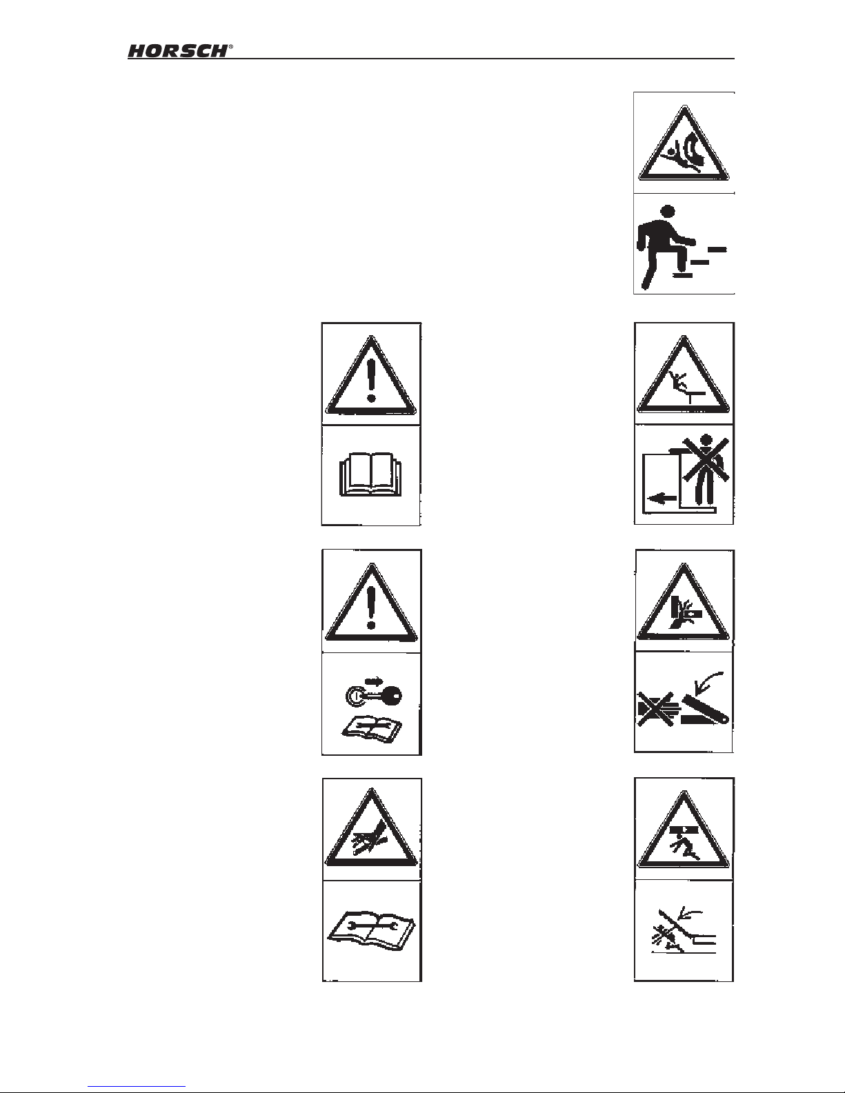
Safety symbols
On the machine
No passengers are allowed to
ride on the machine!
Stay clear of swinging area
of retractable and extendible
machine parts!
Watch out for uids spraying
out under high pressure, follow
the operating instructions
Read and adhere to the operating instructions before starting
up the machine!
Never reach into areas where
there is a risk of crushing, as
long as parts could still be
moving!
Switch the engine o and pull
out the key before starting
maintenance and repair work.
Do not climb on rotatable parts.
Use mounting steps provided
for this purpose.
12
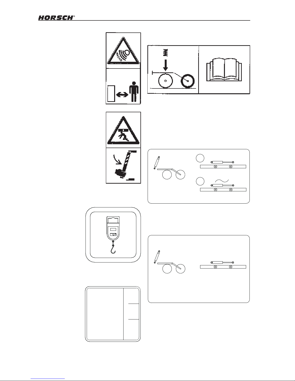
In order to prevent eye injuries,
do not look directly at the beam
area when the radar sensor is
switched on!
It is only permitted to remain in
the danger zone if the safety
support is in place
00380879
OFF
ON
ZERO
Attach the scales here when calibrating.
00380345
1
2
P = 80 ± 10 bar
P = 50 bar
Pronto 7 / 8 / 9 DC
Lower with 50 bar coulter pressure; Preload wing
hydraulics with 80 bar, then switch to oating
position.
00380960 -
P = 80 ± 10 bar
P > 100 bar
Pronto 8 PPF
Lower with at least 100 bar coulter pressure;
Preload wing hydraulics with 80 bar.
Adjust the coulter pressure - read the operating
instructions.
The filling level must be between min. and
max.
max
mi n
™l t yp:
HLP 46
DI N 51524
Tei l 2
Temp: max 60° C
00380093
13
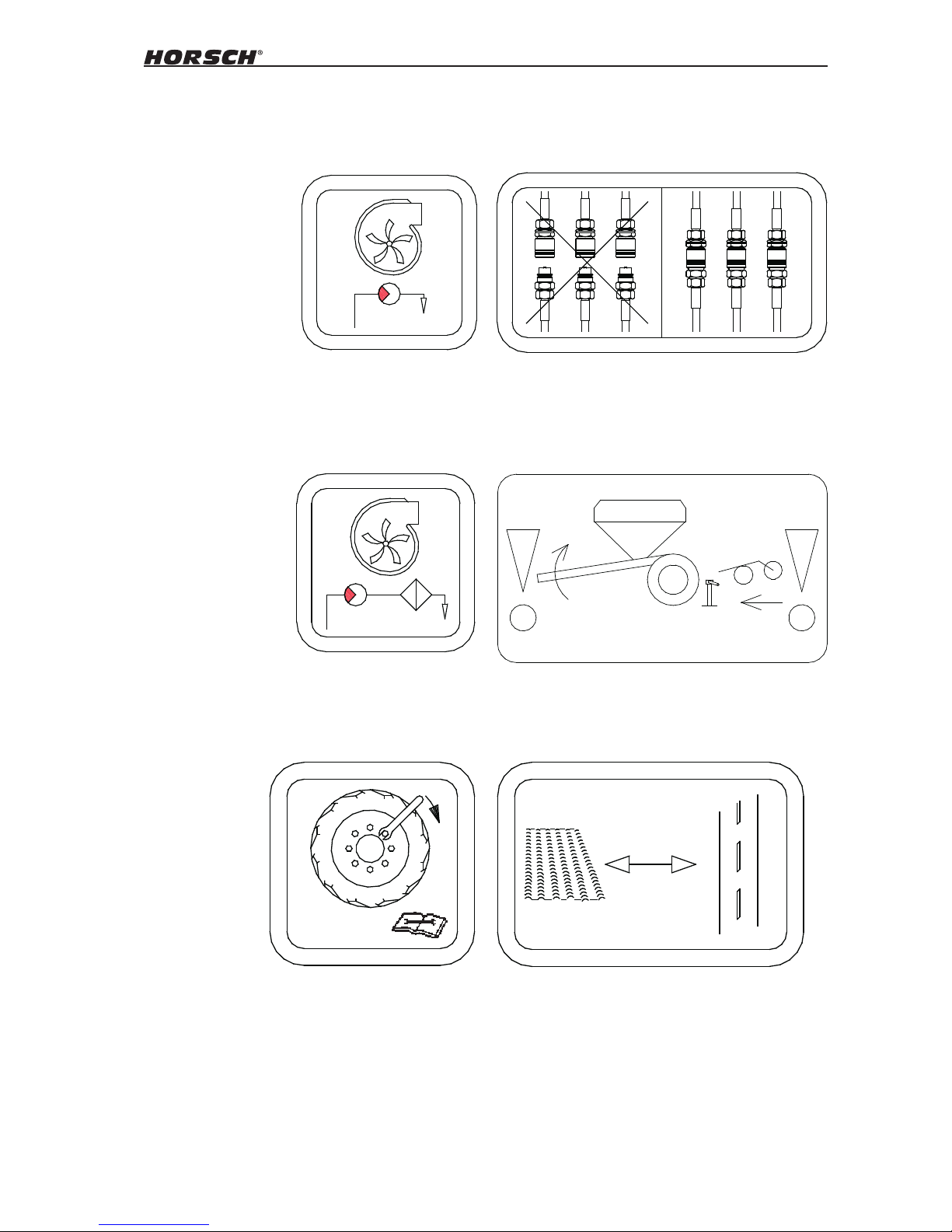
The return ow pressure at the fan drive must
not exceed 5 bar, as otherwise the hydraulic
motor may be destroyed.
00380242
max. 5 bar
00380319
max. 2 bar
If the return ow pressure exceeds 2 bar replace
the lter and change the oil.
00380353
If the disc tools are not installed, put the front
and rear supports in place before parking.
00380212
..
. .
.
.
..
. .
.
.
Always plug in all hydraulic lines. Otherwise
components could be damaged because of
interconnected hydraulic functions.
Retighten the wheel nuts / wheel bolts after
50 hours.
00380359
50 h / Nm
Lever position when switching between working
and transport positions
00380358

14
00110681 00110682
00110687
00110687
00110687
00110681 00110682
00110683 00110684
00110687
Hydraulic valve block
Filling auger
Machine up / down
Unfold / fold machine
Tools
Bout marker
Fan
Identication marks on hydraulic hoses
The symbol is always found on the hose requiring pressure to bring the machine to transport
position (raising, folding, etc.).
00380880
Lifting hook; attach lifting tackle (chains, ropes,
etc.) here when performing loading work.

15
Operational safety
The machine must only be put into operation
after receiving instructions by employees of the
authorized dealer or a HORSCH employee. The
machine registration form has to be completed
and returned to HORSCH.
All protective features and safety equipment,
such as detachable protective devices, must be
correctly in place and reliably functioning before
the machine is put into operation.
¾ Check and tighten nuts and screws at regular
intervals.
¾ Check tyre pressure regularly.
¾ In case of malfunctions stop and secure the
machine immediately!
Road trafc safety
The valid road trac regulations are to be observed when travelling on public roads, paths
and areas.
Do not exceed the max. permissible widths
and attach light system, warning and protective
devices.
Also observe transport height depending on the
coupled machine!
Do not exceed the permissible axle loads, tyre
carrying capacities and total weights, in order
to ensure sucient steering and braking capabilities. Handling is aected by the implement
connected. It is important to take into account
the large overhang and the centrifugal mass of
the implement, particularly when cornering.
The whole machine is to be cleaned of soil
that has been collected before travel on public
roads.
Passengers are strictly forbidden to ride on the
machine.
On public roads travel at a maximum speed
of 25 km/h and only with am empty seed
hopper.
Accident prevention
In addition to the operating instructions, it is
important to observe the accident prevention
regulations specied by agricultural trade associations!
Hitching up / unhitching
There is risk of injury to persons when hitching
up / unhitching the machine to the drawbar of
the tractor.
¾ Secure the machine against rolling away.
¾ Take special care when reversing the tractor.
Never stand between tractor and machine.
¾ Only park the machine on a rm and level
surface. Before unhitching the machine, lower
it to the ground.
Brake system
Depending on the equipment, the machines can
be equipped with a pneumatic or a hydraulic
brake system.
For road transportation the brake system must
always be connected and fully functional.
After hitching the machine and before transportation you should always check the function and
condition of the brake system.
Always secure the machine against rolling away
and apply the parking brake before unhitching.

16
Hydraulic connections
¾ Do not connect hydraulic lines to the tractor,
before both hydraulic systems (machine and
tractor) are de-pressurised.
¾ The hydraulic system is under high pressure.
Check all lines, hoses and screwed connections regularly for leaks and any visible
external damage!
¾ Only use appropriate aids when checking for
leaks. Repair any damage immediately! Oil
sprays can cause injuries and re!
¾ In the case of injury, contact a doctor im-
mediately!
Power sockets and connectors on the hydraulic
connections between the tractor and machine
should be colour-coded in order to exclude operating errors.
The control units on the tractor must
be secured or locked when not in use
or when the machine is in transport
position, in order to prevent accidents
caused by unintended hydraulic movements or movements caused by persons other than the operator (children,
passengers).
Changing implements
¾ Secure the machine against unintended roll-
ing!
¾ Secure lifted frame parts, under which you will
be working, with suitable supports!
¾ Caution! Danger of injury caused by protrud-
ing parts (harrow, tines, share)!
¾ Do not use packer tyres or other rotating parts
when climbing onto the machine. These could
start to rotate and you could fall and be seriously injured.
In operation
¾ Check the area around the machine (for chil-
dren!) before setting o and starting operation
of the machine. Ensure sucient visibility.
¾ Do not remove any of the mandatory and
supplied protective devices.
¾ Stay clear of the operating range of hydrauli-
cally operated parts.
¾ Only use ascending aids and steps when
machine is at standstill. Passengers are not
allowed to ride on the machine during operation!

17
Service and maintenance
¾ Ensure that regular tests and inspections are
always carried out to schedule, as specied
in the operating instructions.
¾ Prior to performing maintenance and servicing
work, ensure that the machine is positioned
on rm, level ground and that it is properly
secured against rolling away.
¾ De-pressurise the hydraulic system and lower
or support the implement.
¾ Before cleaning the machine with high pres-
sure cleaning equipment cover all openings,
which should stay clear of water, steam or
cleaning agents for reasons of safety or operation. Do not aim the water jet directly at
electrical or electronic components, bearings
or the fan.
¾ After cleaning, check all hydraulic lines for
leaks and loose connections.
¾ Check hoses for chang and signs of other
damage. Remedy any faults immediately!
¾ Prior to working on the electrical system, dis-
connect it from the electric power supply.
¾ When performing welding work on the ma-
chine, disconnect the cables from computers
and other electronic components. The ground
connection must be as close as possible to
the welding point.
¾ Retighten screwed connections which had
been loosened during servicing and mainte-
nance work.
Do not wash new machines with a
steam-jet or high-pressure cleaner. The
paint takes approx. 3 months to cure
and could thus be damaged if this time
has not yet expired.

18
Transport/Installation
There is increased risk of accident on initial
installation. Please pay attention to the instructions in the appropriate chapters.
Delivery
The seeder and optional equipment is usually
delivered with a low-loader in a fully assembled
condition.
If parts or optional equipment are disassembled
for transportation then they are assembled onsite by our distribution partners or our company
tters.
The machine can be unloaded with a tractor or
has to be lifted o with suitable lifting gear (fork
lift or crane) depending on the version of the
low-loader.
Pay attention that the lifting equipment and
hoisting devices provide sucient load bearing
capacity.
The bearing pressure and clamping points are
indicated by stickers.
Attention is to be paid to the centre of gravity and
distribution of weight for other hitching points.
These points should denitely only be attached
to the frame of the machines.
Machines with DrillManager ME
The lifting / lowering hydraulic function does
not need to be additionally installed in all machines with the DrillManager ME seeder control
panel.
These machines can be unloaded from the
low-loader without the basic equipment having
to be installed.
Further hydraulic functions like wings or bout
markers can only operated from the tractor after
the basic equipment has been installed.
The function " wings" is connected to its own
control unit in some versions.
Installation
Our customer service employees or distribution partners are responsible for instructing the
operator and carrying out the initial installation
of the machine.
Use of machine prior to instruction is
prohibited!
The machine can only be cleared for operation
after instructions have been made by customer
service employees or distribution partners and
the operating instructions have been read.
There is increased risk of accident
when carrying out installation and
maintenance work. Make yourself familiar with the machine and read the
Operation Manual before carrying out
installation and maintenance work.
Depending on equipment
¾ Remove the bulk components supplied on
delivery from the machine.
¾ Remove all components from the seed hop-
per!
¾ Check all important screw connections!
¾ Lubricate all lubricating nipples!
¾ Check the air pressure in the tires!
¾ Check all hydraulic connections and hoses
for mounting and function.
¾ Immediately eliminate defects or have de-
fects eliminated!
19
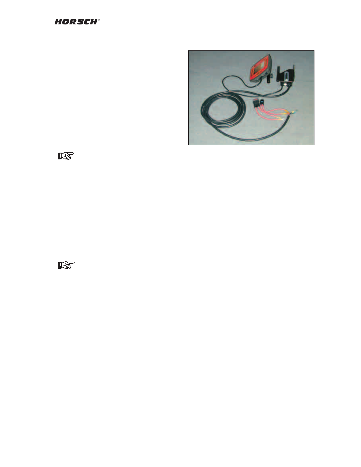
Assembly:
Basic equipment with screen
¾
Assemble the screen holder in a suitable
place within the operator's area of visibility
and operation.
¾ Route the thick cable to the battery and trim,
if necessary.
¾ Tightly and permanently connect both fuse
holders to the cable.
¾ Tightly connect both red cables to the plus
on the battery and both black cables to the
minus on the battery.
¾ Attach the screen holder to the screen and
x the connecting cable on the underside of
the screen.
Install DrillManager
The basic equipment has to be installed on the
tractor during initial installation in all machines
with seeder controls.
The cables for the basic equipment have to be
directly connected to the battery on the tractor.
The cables should not rub and the insulation
should not be damaged.
The connections have to make good connect
with the battery. Assembly errors result in voltage drops and undenable error messages and
malfunctions.
The cables should never be connected
to other connectors in the operator's
cabin.
DrillManager Müller (ME)
The basic equipment is tted with 2 x 6 mm² and
2 x 2.5 mm² cables respectively for the electrical
power supply.
Only the two 6 mm² cables have to be connected
in deliveries up to approx. May 2006 (only one
50 A fuse is available).
From approx. May 2006, all cables have to be
connected (an additional 10 A fuse is available
for the red 2.5 mm² cable).
The screen should not impair the operator's visibility of the road
20
Adjusting the bout markers
No persons are to remain within the
operating range of the bout markers.
There are pinching or shearing points
on all moving parts.
When installing for the rst time, the bout markers must be set to working width. The marking
takes place in relation to the centre of the trac-
tor.
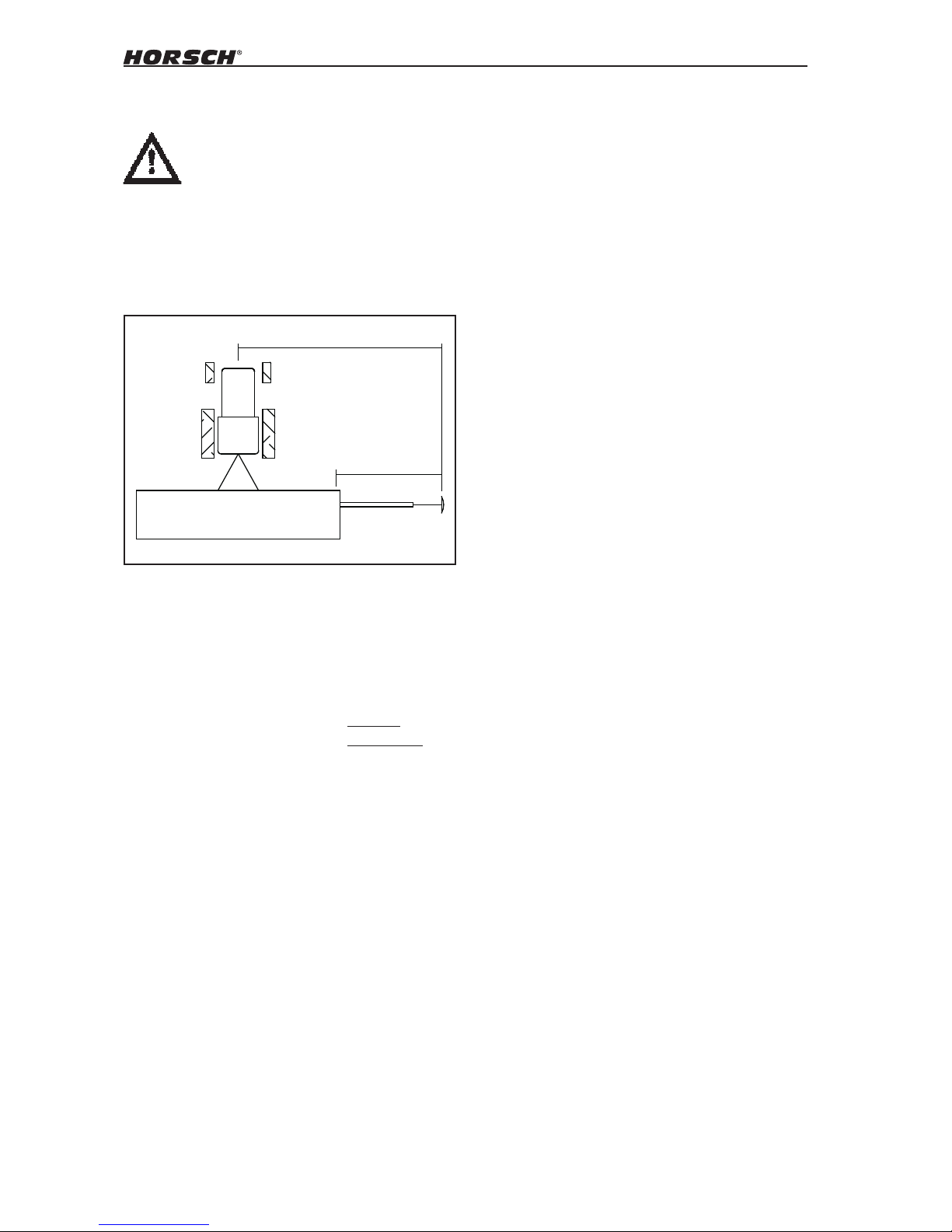
Setting the bout markers
The setting length of the bout markers is half
the machine width plus half the coulter spacing, measured from the centre of the outermost
coulter.
E.g.: 800 cm : 2 = 400 cm
400 cm + 7,5 cm = 407.50 cm
The bout markers on
Pronto 7 DC must be set to 3,57 m
Pronto 8 DC must be set to 4,07 m
Pronto 9 DC must be set to 4,57 m
Pronto 8 PPF must be set to 4,07 m
from the middle of the outermost coulter.
8,0 m
4,07 m
Pronto 8 DC = 8 m

21
Technical data
Pronto 7 DC
Dimensions and weights
Transport width: ....................................3,00 m
Transport height: ..................................3,60 m
Length:..................................................8,80 m
Working width: ...................................... 7,50 m
Curb weight: ........................... max. 10.500 kg
Drawbar weight:............................0 - 1,500 kg
Hopper capacity:.................................... 4000 l
Standard version
Number of coulters: .....................................52
Coulter spacing:..................................144 mm
Sowing depth: ................................0 - 100 mm
Coulter pressure: ............................. 5 - 120 kg
Metering unit drive: ......................... electronic
Metering:.....................................2 - 500 kg/ha
Hydraulic fan:...................................4.000 rpm
Tractor power required
Tractor power from: ..................145 - 205 KW
Hydraulic pressure: .............................180 bar
1 x double acting: .........................Hydr. block
1 x double acting with
ow control valve: ......................................Fan
1 x freeow return max.: 5 bar ........ case drain
Oil quantity with direct fan drive: ........35 - 45 l
Pronto 8 DC
Dimensions and weights
Transport width: ....................................3,00 m
Transport height: ..................................3,60 m
Length:..................................................8,80 m
Working width: ...................................... 8,00 m
Curb weight: ........................... max. 10.700 kg
Drawbar weight:............................0 - 1,500 kg
Hopper capacity:.................................... 4000 l
Standard version
Number of coulters: .....................................52
Coulter spacing:..................................154 mm
Sowing depth: ................................0 - 100 mm
Coulter pressure: ............................. 5 - 120 kg
Metering unit drive: ......................... electronic
Metering:.....................................2 - 500 kg/ha
Hydraulic fan:...................................4.000 rpm
Tractor power required
Tractor power from: ..................155 - 215 KW
Hydraulic pressure: .............................180 bar
1 x double acting: .........................Hydr. block
1 x double acting with
ow control valve: ......................................Fan
1 x freeow return max.: 5 bar ........ case drain
Oil quantity with direct fan drive: ....... 35 - 45 l
 Loading...