

horsch Maestro 16 SW, Maestro 24 SW, Maestro 36 SW Operating Instructions Manual
OPERATING INSTRUCTIONS
Maestro 16/24/36 SW
TRANSLATION OF THE ORIGINAL OPERATING INSTRUCTIONS
READ CAREFULLY PRIOR TO STARTING UP!
KEEP OPERATING INSTRUCTIONS IN A SAFE PLACE!
ART.:
ISSUE:
8043
02/2018
0225


- Translation of the Original Operating Instructions -
Machine Identication
The corresponding data is to be entered into the list below upon
receiving the machine:
Serial number: ..................................................
Machine type: ...................................................
Year of construction: ........................................
Initial installation: ..............................................
Fittings: .............................................................
..........................................................................
..........................................................................
..........................................................................
Publication date of Operation Manual:
Latest change:
Address of Retailer: Name: ......................................................................
Road: ......................................................................
Town/City: ......................................................................
Tel.: ......................................................................
Customer No.:
Retailer: ......................................................................
Address of HORSCH: HORSCH Maschinen GmbH
92421 Schwandorf, Sitzenhof 1
92401 Schwandorf, Postbox 1038
Tel.: +49 (0) 9431 / 7143-0
Fax: +49 (0) 9431 / 7143-9200
E-mail: info@horsch.com
Customer No.:
HORSCH: ......................................................................
02/2018
8043 25
Maestro 16/24/36 SW
02
en
Conrmation of receipt of machinery
Warranty claims become only eective when the rst use of the machine is reported to HORSCH
Maschinen GmbH within a week.
At www.horsch.com under SERVICE PARTNERBEREICH an interactive PDF form is available for down-
load for this purpose (not available in all languages).
By clicking on Send – depending on the email program installed – a mail draft with the completed
form is generated automatically. Alternatively, the form can be sent as email attachment to machine.
registration@horsch.com.
A dierent form of registration (postal mail, by fax, etc.) is not allowed for.

EC Declaration of Conformity
Exchangeable equipment
(Directive 2006/42/EC)
The manufacturer HORSCH Maschinen GmbH
Sitzenhof 1
D- 92421 Schwandorf
hereby declares, that the product,
Designation of machine: Drill unit
Machine type: Maestro 16 SW from serial number: 24651280
Maestro 24 SW from serial number: 24581426
Maestro 36 SW from serial number: 24611262
this declaration refers to, conforms with all relevant fundamental health and safety requirements of
the EC directive 2006/42/EC.
For proper implementation of the health and safety requirements mentioned in the EC-directive,
the following standards and technical specications have been used:
• DIN EN ISO 4254-1 2013-10
• DIN EN 14018 2010-02
• DIN EN ISO 12100 2011-03
Schwandorf, 23/05/2016 Manfred Köbler
Place and date Documentation ocer
________________________ ________________________
Michael Horsch Philipp Horsch
(Managing director) (Managing director)


Table of contents
Introduction ...................................................4
Foreword ........................................................4
Notes on representation .................................4
Service............................................................5
Warranty claim processing .............................5
Consequential damage...................................5
Safety and accident prevention ..................6
Intended use ...................................................6
Qualication of personnel ...............................7
Children in danger ..........................................8
Personal protective outt ................................8
Safety in trac ................................................8
Safety in operation..........................................9
Fertiliser and dressed seed ..........................13
Environmental protection ..............................13
Retrots ........................................................14
Care and maintenance .................................14
Danger zone .................................................15
Safety stickers ..............................................16
Technical data .............................................19
Type plate .....................................................21
Requirements for the tractor .........................25
Structure......................................................28
Overview.......................................................28
Hydraulics .....................................................29
Identication of hydraulic hoses ...................35
Aluminium clips.............................................35
Lighting .........................................................36
Instruction stickers ........................................37
Commissioning ...........................................41
Delivery.........................................................41
Transport ......................................................41
Installation ....................................................41
Operation .....................................................42
Commissioning / Tractor change ..................42
Adapting the propshaft...............................42
Adjust the height of drawbar eye/
spherical cap ..............................................43
Connecting/Parking ......................................43
Connecting ...................................................43
Transport position .........................................45
Parking .........................................................46
Folding ..........................................................48
Unfolding ....................................................48
Folding .......................................................48
Use in the eld ..............................................50
At the headland ..........................................50
Checks..........................................................52
Pneumatic system ......................................53
Hopper ..........................................................53
Railing...........................................................54
Solid fertiliser facility .....................................54
Fan - fertiliser ...............................................56
Direct drive .................................................56
Fan with PTO-shaft pump ..........................57
Maestro 24 SW ..........................................58
Maestro 36 SW ..........................................58
Fan speeds ................................................61
Fertiliser quantities .....................................61
Retightening the fan ange ........................62
Fan - vacuum................................................63
Seed on Demand system .............................64
Fertiliser metering unit...............................67
Rotors ...........................................................67
Rotor change ................................................68
Rotor change with gate valve .......................68
Rotor change at full hopper
without gate valve .........................................69
Adjusting the sealing lip ................................69
Maintenance of metering unit .......................70
Fertiliser coulter ............................................71
Single-disc coulter (option) ........................73
Aligning the seed bar ....................................77
2

Single grain metering .................................78
Single grain metering unit .............................79
Overview ....................................................79
Components in the metering unit ...............81
Adjusting the metering unit ........................89
Checks .......................................................93
Problems and rectication .........................94
Downpipe......................................................96
Single grain coulter discs..............................98
Depth guide rollers .......................................99
Trap roller ...................................................100
Setting the drilling depth .............................101
Adjusting the coulter pressure ....................103
Press rollers................................................104
Clearing stars (option) ................................108
Troubleshooting Maestro ............................ 110
Optional equipment .................................. 111
Micro-granulate facility SW ......................... 111
Adjustment and operation ........................ 111
Seed calibration ....................................... 112
In use ....................................................... 114
Pneumatic brake......................................... 11 6
Hydraulic brake........................................... 11 8
Parking brake ........................................... 11 9
Filling screw ................................................120
Agitator shaft ..............................................122
ContourFarming..........................................122
AutoForce ...................................................123
Fertiliser ow monitoring.............................123
Waste disposal .........................................134
Appendix ...................................................135
Tightening torques ......................................135
Adjusting the propshaft ...............................137
Determine the operating lengths..............137
Shortening the propshaft .........................138
Index ..........................................................141
Care and Maintenance .............................124
Maintenance intervals.................................125
Storage .......................................................125
Lubricating the machine .............................125
Maintenance overview
Maestro 16/24/36 SW .................................126
Lubrication points .......................................131
3

Introduction
Notes on representation
Warning notes
Foreword
Before commissioning the machine, read and
strictly comply with the operating instructions. In
doing so, you will avoid accidents, reduce repair
costs and downtime and increase the reliability
and service life of your machine. Pay attention
to the safety notes!
HORSCH will not assume liability for any damage or malfunctions resulting from failure of
complying with the operating instructions.
These operating instructions will assist you in
getting to know your machine and using it correctly for its intended purposes.
The operating instructions must be read and
strictly adhered to by all persons working on or
with the machine e.g.:
• Operation (including preparation, fault recti-
cation during work, care)
• Maintenance (maintenance, inspection)
• Transport
These operating instructions distinguish be-
tween three dierent types of warning notes.
The following signal words with warning sym-
bols are used:
DANGER
Highlights a danger that will lead to death or
severe injury if it is not avoided.
WARNING
Highlights a danger that may lead to death or
severe injury if not avoided.
CAUTION
Highlights a danger that can lead to injuries if
not avoided.
Please read the warning notes given in these
operating instructions!
Instructions
Trained personnel of our service and sales
partners will instruct you in the operation and
care of your machine. By submitting the ac-
knowledgement of receipt you have conrmed
proper acceptance of the machine.
The warranty period starts with the date of
delivery.
We reserve the right to alter illustrations as well
as technical data and weights contained in these
operating instructions for the purpose of improving the machine.
The illustrations in these operating instructions
show dierent versions of the implement and
dierent equipment variants.
NOTE
Identies important notes.
Take-action instructions are indicated by arrow
points:
¾ ...
¾ Keep the order of the instructions. Alternatively,
instructions may be numbered consecutively.
The designations right, left, front and rear apply as
seen in travel direction.
4

Service
Consequential damage
HORSCH Company would like you to be completely satisfied with your machine and our
services.
If you encounter any problems, please feel free
to contact your sales partner.
The service sta of our sales partners and the
service employees at HORSCH will always be
available to assist you.
In order to be able to solve technical problems
as quickly as possible, we ask you kindly to
support us.
Please help the service personnel by providing
the following information to avoid unnecessary
queries.
• Customer number
• Name of customer representative
• Name and address
• Machine model and serial number
• Purchasing date and operating hours or
area performance
• Type of problem
The machine has been manufactured by
HORSCH with greatest care. However, despite
the intended use deviations in placing quantity
up to total failure may be caused by e.g.:
• damage caused by external inuences
• wear of wear items
• missing or damaged cultivation tools
• incorrect drive motor speeds and travel
speeds
• incorrect setting of the unit (incorrect con-
nection, non-observance of setting tables)
• failure to comply with the operating instruc-
tions
• dierences in the composition of seed or
fertiliser (i.e. grain size distribution, density,
geometrical shape, dressing, sealing)
• blockages or seed bridging (i.e. caused by
foreign bodies, non-smooth seeds, sticky
dressing, moist fertiliser)
• neglect and improper care and maintenance
Therefore, it is crucial to always check your machine before and during use for correct operation
and adequate application accuracy.
Warranty claim
processing
Warranty claim forms must be submitted to
HORSCH through your local HORSCH sales
partner.
Compensation claims for damages that have
not occurred on the machine are excluded. This
also means that any liability for consequential
damages caused by travel and operating faults
is excluded.
5

Safety and accident
Any other kind of use of the machine contradicting the above, especially
prevention
The following warnings and safety notes apply
to all sections in these operating instructions.
The machine has been built in accordance with
latest technical standards and generally accepted safety regulations. However, risks for
life and limb of the operator or third parties and
impairment of the machine or other material assets can occur during use.
Please read and comply with the following safety
notes, before you start to use the machine!
Intended use
The machine is intended for the singulation
and placement of seed as well as metering and
placement of owable fertiliser on agricultural
areas.
The intended use also includes taking note
of and observing the notices and instructions
given in these operating instructions, observing
all pictograms and warnings on the machine,
observing all maintenance and repair intervals
and complying with the dened technical limits
and areas of application.
When participating with the machine in public
road trac, the respective national registration
and trac law must also be complied with.
• connecting/attachment to an agricultural trac-
tor that is not suitable
• using the machine as a means of transport
• operating the machine while persons are still
in the danger zone (this includes in particular
transport rides on the machine)
• carrying out maintenance and/or repair work
on a machine that has not been shut down or
is not secured against restarting
are considered not as intended.
Horsch does not assume any liability for damages resulting from the unintended use of the
machine.
Spare parts
Genuine spare parts and accessories from
HORSCH have been specially designed for this
machine.
Spare parts and accessories which are not delivered by us have not been tested or approved
by us.
Installation or use of non-original HORSCH
products may have a detrimental effect on
specic design features of the machine and
impair the safety of machine operators and the
machine itself.
HORSCH will not assume liability whatsoever for
damage resulting from the use of non-original
parts and accessories.
If the component to be replaced is marked with
a safety sticker, these stickers must also be
ordered and attached to the spare part.
6

Operating Instructions
The owner of the machine must
Intended use also includes strict compliance with
the operating instructions and adherence to the
operating, maintenance and repair instructions
specied by the manufacturer.
The operating instructions are a part of the
machine!
The machine is solely intended for use as described in the operating instructions. Failure to
comply with the operating instructions can result
in severe or even fatal physical injuries.
¾ Read and follow the corresponding sections
in the operating instructions before starting
work.
¾ Store the operating instructions and keep for
future use.
¾ Pass the operating instructions on to a later
user.
Qualication of personnel
Unintended use of the machine can lead to severe or even fatal physical injuries. In order to
prevent accidents, each person involved in work
with the machine must meet the following general
minimum requirements:
¾ The person must be physically able to keep
the machine under control.
¾ The person is able to perform work with the
machine safely within the scope of these operating instructions.
¾ The person is acquainted with the function of
the machine within the scope of its work and
is able to assess and avoid any work related
dangers. The person is able to recognize and
avoid work related dangers.
¾ The person has understood the operating
instructions and is able to implement the information given in the operating instructions
accordingly.
¾ The person is fully familiar with the safe opera-
tion of the vehicle.
¾ The person knows all applicable road trac
regulations and is in possession of a valid
driving permit for road travel.
¾ A person being instructed must only work with
or on the machine under the supervision of
an experienced person.
¾ regulate the area of responsibility, compe-
tence and monitoring of personnel.
¾ if necessary train and instruct the personnel.
¾ make the operating instructions accessible for
the machine operator.
¾ ensure that the operator has read and under-
stood the operating instructions.
Groups of operators
Persons who work with the machine must have
been trained for the dierent activities involved.
Instructed operators
These persons must have been trained for
their respective activities by the owner or other
qualied experts. This refers to the following
activities:
• Road transportation
• Application and set-up work
• Operation
• Maintenance
• Troubleshooting and repair
Operators trained by HORSCH
Furthermore, for certain activities the corresponding personnel must have been trained by
service personnel from HORSCH. This refers to
the following activities:
• Loading and transport
• Commissioning
• Troubleshooting and repair
• Waste disposal
Certain work concerning maintenance and repair
must only be carried out by an expert workshop.
Such work is identied with the additional comment Workshop work.
7

Children in danger
Children are not able to assess dangers and may
behave unpredictably. Children are therefore
especially endangered:
¾ Keep children away from the machine.
¾ Especially before drive o and before trigger-
ing machine movements you must make sure
that the danger zone is free of children.
¾ Shut down the tractor before leaving it.
Children can trigger dangerous machine
movements. An insuciently secured machine parked without being attended poses
a danger for playing children!
Personal protective outt
Missing or incomplete protective equipment
increases the risk of health damage. Personal
protective equipment includes, e.g.:
¾ tight tting clothes / protective clothing, pos-
sibly a hair net
¾ safety shoes
¾ safety gloves
¾ safety goggles to protect the eyes against
dust or spray, when working with fertiliser or
liquid fertiliser (follow the instructions of the
fertiliser manufacturer)
¾ respirator masks and protective gloves when
handling dressing or dressed seed (follow
the instructions of the pickling agent manufacturers)
¾ Determine the personal protective equipment
for the corresponding work place.
¾ Provide effective protective equipment in
proper condition.
¾ Never wear rings, bracelets or other jewellery.
Safety in trac
DANGER
No passengers are allowed to ride on the
machine!
¾ Pay attention to the permissible transport
widths and heights. Pay attention to the transport height when passing under bridges and
low hanging overhead power lines.
¾ Do not exceed the permissible axle load, tyre
load bearing capacity and total weight, in order
to ensure sucient steering and braking capabilities. The front axle must be loaded with at
least 20% of the tractor weight.
¾ For machines without brake select the weight
of the tractor and the speed so that the machine can be managed securely under all
conditions.
For road transport the machine must be set to
transport position. The machine must have been
folded up and secured, see chapter Folding and
Connecting and Transport position.
¾ Clean soil from the folding areas before fold-
ing up. Otherwise there could be damage to
the mechanics.
¾ If present: Secure the hydraulic cylinders on
undercarriage and drawbar in transport position against uncontrolled movements using
aluminium clips, see chapters Connecting and
Transport position.
¾ Assemble lighting, warning and protective
features and check the function.
¾ Before road travel clean the entire machine
from picked up dirt.
Handling is aected by the connected equipment.
¾ Consider the wide overhang and the centrifu-
gal mass of the implement as well as the lling
capacities, especially when cornering.
For transport on public roads, only drive
with empty seed hopper.
8
Pay attention to the permissible top
speed in accordance with the type approval for transport on public roads!
Safety in operation
Commissioning
The specications in the type approval
document or in the technical data are
decisive for the design dependent top
speed.
Always match the travel mode to the
road conditions to avoid accidents and
damage to the undercarriage.
Consider your personal abilities, carriage
way, trac, sight and weather conditions.
Pay attention also to the notes in chapter
Commissioning!
The hydraulic cylinders on the undercar-
riage must be lled up with spacers, the
machine must be lowered on these spacers.
The operational safety of the machine cannot be
guaranteed without orderly performed commissioning. This can lead to accidents with severe
or even fatal physical injuries.
¾ The machine must only be put into operation
after receiving instructions by employees of
the authorized dealer or a HORSCH employee.
¾ The machine registration form must be com-
pleted and returned to HORSCH.
Only use the machine with all protective features
and safety relevant installations, such as e.g.
detachable safety features, in place and fully
functional.
¾ Check nuts and bolts, especially the ones on
wheels and cultivation tools regularly for tight
t and retighten if necessary.
¾ Check tyre pressure regularly.
Damage to the machine
Damage to the machine can impair the operational safety of the machine and cause accidents. This can lead to severe or even fatal
physical injuries.
The following machine parts are particularly
important for safety:
¾ Hydraulics
¾ Brakes
¾ Connecting features
¾ Protective features
¾ Lighting
If in doubt about the safety-relevant status of
the machine, e.g. in case of leaking operating
uids, visible damage or unexpected changes
in travel behaviour:
9

¾ Immediately shut down and secure the ma-
chine.
¾ If possible locate and rectify the faults by fol-
lowing these operating instructions.
¾ Rectify possible causes for damage (e.g. re-
move coarse dirt and tighten loose screws).
¾ Have damage that could aect safety and
that cannot be rectied by you rectied by a
qualied expert workshop.
Hydraulics
The hydraulic system is under high pressure.
Escaping uid can penetrate the skin and cause
serious injuries. In the event of injury, consult a
doctor immediately.
The machine's hydraulics has several functions,
which can cause injury to persons or damage to
the machine if operated incorrectly.
Coupling and unhitching
Faulty coupling of the machine to the pulling tool
of the tractor causes dangers, which could result
in severe accidents.
¾ Caution with negative drawbar load!
With an empty hopper and under certain operating conditions the machine may have a
negative drawbar load.
The rear axle of the tractor is unloaded. This
has a negative eect on the steering and
braking characteristics.
Caution when unhitching!
Always fold the wings in or rest them on the
ground beforehand.
¾ Only park the machine on a rm and level sur-
face. Before unhitching the towed machine,
lower it to the ground. The machine could
otherwise strike up! The seed wagon could
tip backwards!
¾ Strictly comply with all operating instructions:
• These operating instructions (chapter Con-
necting, Transport position and Parking)
• Operating instructions of the tractor
• if necessary the operating instructions for
the propshaft
¾ Exercise special caution when reversing the
tractor. Never stand between tractor and
machine.
¾ Secure the machine against rolling away.
¾ Do not connect hydraulic hoses to the tractor,
before both the hydraulics on machine and
tractor are de-pressurised.
¾ Lower all hydraulically lifted parts (e.g. wings,
packer, undercarriage, etc.) to the ground
before performing any work on the hydraulic
system. Depressurise the hydraulics on the
tractor and implement side.
¾ The hydraulic system is under high pressure.
Check all lines, hoses and screwed connections regularly for leaks and any visible
external damage!
¾ Use only appropriate means when searching
for leaks. Repair any damage immediately!
Oil sprays can cause injuries and re!
¾ Power sockets and connectors on the hydrau-
lic connections should be marked in order to
exclude operating errors.
¾ In the case of injury, contact a doctor imme-
diately!
¾ Secure and lock the control unit on the tractor
if not in use!
¾ Replace hydraulic hoses at the latest after six
years, see Maintenance overview.
Pressure accumulator
The hydraulic system is equipped with pressure
accumulators.
¾ Do not open or work (welding, drilling) on
pressure accumulators. Even when empty,
the tanks are still preloaded by gas pressure.
10
The hydraulics must be depressurized before
maintenance!

Brake system
What to do in case of voltage ashover
Depending on the equipment, the machines can
be equipped with a pneumatically or hydrauli-
cally operated service brake system.
For road travel the brake system must always
be connected and fully functional.
¾ After coupling the machine and before trans-
portation you should always check the function and condition of the brake system.
¾ Check the setting on the brake pressure
regulator. Turn the lever to the Road symbol
(pneumatic brake) before transport travel.
¾ Always release the parking brake before start-
ing to drive.
¾ Always secure the machine against rolling
away and apply the parking brake before
unhitching.
Adjustments and repair work on the brake system must only be carried out in a professional
workshop or by an operator, who has been
specially trained by HORSCH for this purpose.
Overhead lines
Voltage ashover generates high electric voltages on the outside of the machine. This results
in extreme voltage dierences at the ground
around the machine. Wide strides, laying on the
ground or supporting yourself with your hands
on the ground can cause life-threatening electric
currents (pace voltage).
¾ Do not leave the cabin.
¾ Do not touch any metal objects.
¾ Do not create a conductive connection to
ground.
¾ Warn persons: DO NOT come near the ma-
chine. Electric voltages at the ground can
cause severe electric shock.
¾ Wait for professional rescuers. The overhead
power line needs to be switched o.
If persons need to leave the cabin despite the
voltage ashover, e.g. in case of a potential lifethreatening risk of re:
¾ Jump away from the machine. Ensure a safe
stand when jumping. Do not touch the outside
of the machine.
¾ Move away from the machine with short step-
ping strides.
When unfolding or folding the wings, the machine may reach the height of overhead lines.
Possible voltage ashover to the machine causing fatal electric shock or re.
¾ Keep a safe distance to electric high voltage
power lines when unfolding or folding the
machine.
¾ Do not unfold or fold the wings in the vicinity
of pylons and power lines.
¾ With the wings unfolded keep a sucient
distance to electric high voltage power lines.
¾ Never leave or access the machine under
overhead lines to avoid possible risks of
electric shock or voltage ashover.
11

PTO-shaft
Technical limiting values
Persons can be caught, pulled in and seriously
injured by the rotating PTO-shaft and driven
components.
Before switching on the PTO-shaft:
¾ Assemble the protective features and estab-
lish their protective position.
¾ Make sure that the chosen rotary speed and
the sense of rotation of the PTO-shaft corresponds with the permissible values for the
machine.
¾ Make sure that no persons are inside the
danger zone around the PTO-shaft.
¾ Shut down, if the angle of the PTO-shaft is too
large. The machine could become damaged.
Parts may be thrown o and injure persons.
¾ Switch o the PTO-shaft if it is no longer
needed.
Propshaft
Persons can be caught, pulled in and seriously
injured by the rotating propshaft.
If the technical limiting values of the machine
are not complied with, the machine may sustain
damage. This can lead to accidents with severe
or even fatal physical injuries.
The following technical limiting values are of
particular importance for safety:
• permissible total weight
• maximum axle loads
• maximum drawbar load
• top speed
See chapter Technical data, type plate and type
approval.
¾ Also pay attention to the max. permitted loads
for the tractor.
Use in the eld
DANGER
No passengers are allowed to ride on the
machine!
¾ Make sure that the PTO-shaft guard is in place
and functional.
¾ Make sure that no persons are inside the
danger zone around the propshaft.
¾ Ensure sucient overlapping of prole tube
and PTO-shaft guard.
¾ Allow PTO-shaft locks to click into place.
¾ Secure the PTO-shaft guard with chains
against rotating.
¾ Follow the operating instructions for the
propshaft.
¾ Check the area immediately around the ma-
chine (for children!) before driving o and
commissioning the machine. Ensure sucient
visibility.
¾ Check the condition of the cultivation tools
and their mounting before use.
¾ Ensure sucient stability of the machine in
case of longitudinal or transverse inclination
when working in uneven terrain. Pay attention
to the limiting values for the tractor.
¾ Do not remove any of the mandatory and
supplied protective devices.
¾ Stay clear of the operating range of hydrauli-
cally operated parts.
¾ Use climbing means and steps only at stand-
still.
¾ Do not drive backwards with the machine
lowered. The components have only been
designed for forward travel in the eld and
may be damaged when reversing.
12

Changing equipment / wear items
Fertiliser and dressed
¾ Only pulling tools may be attached that meet
the technical requirements according to these
operating instructions.
HORSCH does not assume any liability for
damages resulting from the attachment of
non-tting pulling tools as well as incorrect
mounting.
¾ For machines with valid type approval only
pulling tools may be attached that are covered
by the type approval. Attaching pulling tools
not covered by the type approval will void the
registration.
¾ Secure the machine against unintended roll-
ing away!
¾ Secure raised frame parts you have to work
under with suitable supports!
¾ Caution! Danger of injury caused by projecting
parts (e.g. coulters)!
¾ Assume ergonomic working postures with any
assembly work.
¾ Do not use packer tyres or other rotating
parts to climb on the machine. These could
rotate and you could be seriously injured by
falling down.
seed
Inappropriate handling of fertiliser and dressed
seed can cause poisoning and death.
¾ Follow the information given in the safety data
sheet of the manufacturer. If necessary, ask
the dealer for the safety data sheet or safety
notes.
¾ Determine and provide the personal protective
outt as specied by the manufacturer.
Environmental protection
Operating materials such as hydraulic oil, lubricants, etc. can damage the environment and the
health of persons.
¾ Do not allow operating materials to drain out
into the environment.
¾ Take up drained operating materials with
absorbent material or sand, ll it into a leak
tight tank and dispose of in accordance with
statutory regulations.
13

Retrots
Structural changes not approved by HORSCH
may aect the functionality and operational
safety of the machine and will void any warranty
claim.
HORSCH is not liable for damages to life and
limb as well as property damages resulting from
unapproved retrotting and conversions.
¾ Do not perform any structural changes to the
pulling tool of the machine.
¾ Do not make any structural changes or ex-
tensions to the machine that have not been
approved by HORSCH.
¾ Modications and extensions approved by
HORSCH are only to be performed at an authorized workshop or by an operator who has
been trained by HORSCH for this purpose.
¾ Comply with country-specic instructions for
weights, weight distribution and dimensions.
For equipment inuencing the weight or weight
distribution the regulations concerning towing
facility, support and axle load must be checked
and complied with.
For machines without brakes a brake system
may need to be retrotted if the permissible
weight limits are exceeded.
In case of changes concerning data mentioned
on the type plate, a new type plate with updated
data must be attached.
In case of changes which concern the data in
the type approval, this type approval needs to
be renewed.
Care and maintenance
Inappropriate care and maintenance puts the
operational safety of the machine at risk. This
can lead to accidents with severe or even fatal
physical injuries.
¾ Conform to prescribed schedules for repetitive
tests or inspections.
¾ Service the machine according to the mainte-
nance plan, see chapter Care and maintenance.
¾ Only perform the work described in these
operating instructions.
¾ Before starting maintenance and service work
park the machine on level and rm ground and
secure it against rolling away.
¾ Depressurise the hydraulic system and lower
or support the implement.
¾ Prior to working on the electrical system,
disconnect it from the electric current supply.
¾ When performing welding work on the ma-
chine, disconnect the cables from computers
and other electronic components. The ground
connection must be as close as possible to
the welding point.
¾ Before cleaning the machine with high pres-
sure cleaner cover all openings, which should
stay clear of water, steam or cleaning agents
for reasons of safety or operation. Do not aim
the water jet directly at electrical or electronic
components, bearings or the fan.
¾ When cleaning with high pressure cleaning
equipment or steam jets keep a distance of
at least 50 cm to machine components.
¾ Hopper, metering units, hoses and coulters
are contaminated with fertilisers and dressed
seed. Wear suitable protective outt when
cleaning. Avoid contact and do not breath
the exhaust air.
¾ After cleaning, check all hydraulic lines for
leaks and loose connections.
¾ Check for chang and signs of damage. Rem-
edy any faults immediately!
¾ Screw connections loosened for the purpose
of care and maintenance work must be
retighten after work is completed.
¾ Do not clean new machines with a steam jet
of a high pressure cleaner. The paint takes
approx. 3 months to cure and could thus be
damaged if this time has not yet expired.
¾ All other maintenance and repair tasks,
which are not described in the operating
instructions, must only be carried out by
an authorized professional workshop or
by an operator who has been trained by
HORSCH for this purpose.
14

Danger zone
The area marked red indicates the danger zone
of the machine:
The danger zone around the machine poses the
following endangerments:
• Accidental operation of the hydraulic system
can trigger dangerous movements of the
machine.
• With the drive still running, machine parts may
rotate or swing out.
• Hydraulically raised machine parts can lower
slowly and unnoticed.
Failing to pay attention to the danger zone can
result in severe or even fatal physical injuries.
¾ Do not stand under lifted loads. Lower such
loads to the ground rst.
¾ Instruct persons to leave the danger zone
around the machine and tractor before any
machine movements.
¾ Before working in the danger zone of the ma-
chine or between machine and tractor: Shut
down the tractor!
This also applies for short-term inspection work.
Many accidents happen because of carelessness and running machines!
¾ Pay attention to the information in all operat-
ing instructions.
15
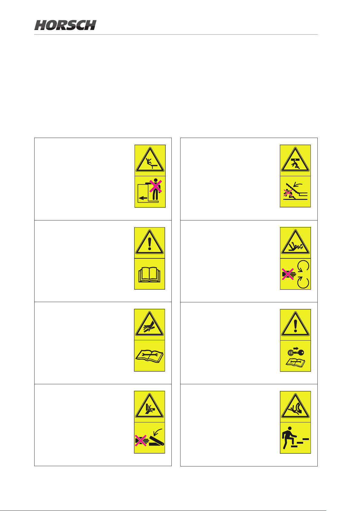
Safety stickers
Safety stickers on the machine warn of hazards
at dangerous points and are an important part
of the safety equipment of the machine. Missing safety stickers increase the risk of severe or
even fatal injuries.
No passengers are allowed to
ride on the machine!
00380054
Before commissioning the machine you need to read and follow the operating instructions!
¾ Clean soiled safety stickers.
¾ Damaged or illegible safety stickers must be
replaced immediately.
¾ Provide spare parts with the specied safety
stickers.
Stay clear of the operating
range of foldable machine parts!
00380135
Never reach with your hands in
the rotating auger.
Caution for uids spraying out
under high pressure, follow the
notes in the operating instructions!
Never reach into areas where
there is a risk of crushing as long
as parts could still be moving!
00380055
00380133
00380134
00380163
Shut the engine down and pull
o the key before starting maintenance and repair work.
00380294
Do not climb on rotatable parts.
Use mounting steps provided
for this purpose.
00380299
16
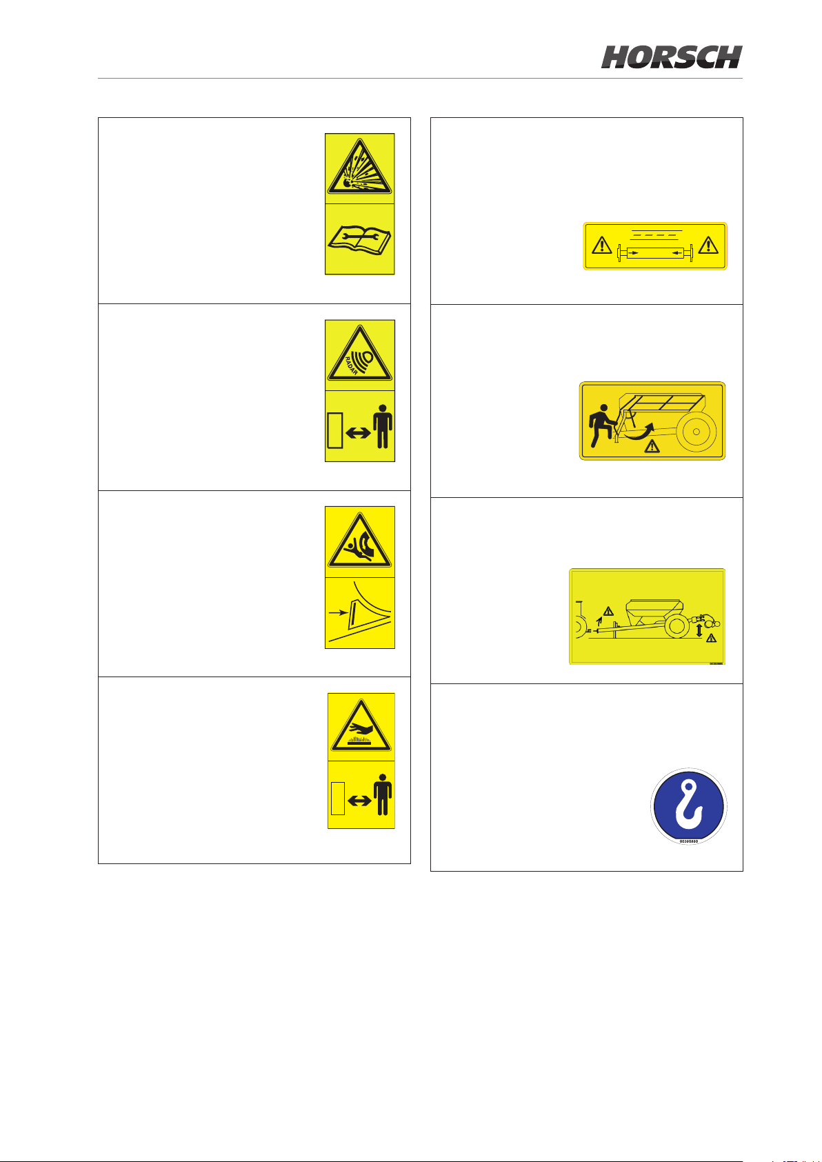
The pressure accumulator is
charged with gas or oil pressure. Dismantle and repair
only in strict compliance with
the instructions in the technical
manual.
00380252
Attention: For road travel the axle must be
retracted to transport width.
00380598
00380598
In order to prevent eye injuries,
do not look directly at the beam
area when the radar sensor is
switched on!
Secure the machine with wheel
chocks before uncoupling or
parking.
Keep sucient distance to hot
surfaces.
00380894
00381116
Fold the railing up before accessing. Fold
the railing down before folding up the machine.
00385752
In case of a negative drawbar load the
drawbar may jerk upward when unhitching!
Lower the seed bar all the way before
unhitching!
00380986
Loading hook;
hook the load suspension gear (chains,
ropes etc.) into this loading hook during
loading.
04001453
17
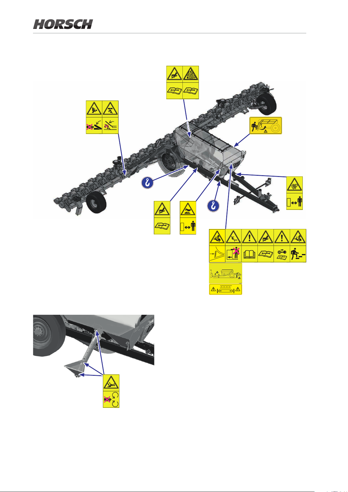
Position of safety stickers
(depending on equipment)
2x
2x
2x
In addition with auxiliary lling auger equipment
*
00380598
Safety stickers with the addition “2x” can be found on either side of the machine.
*For PTO-shaft drive equipment
18

Technical data
Maestro
Transportwidth (m) 3.00 / 3.12 at 16.70/30″ SW 3.00
Transportheight (m) 4.00 4.00
Transportlength (m) 8.06 8.06
Weight incl. seed wagon from (kg) 9 857 11 830
Electrical coulter pressure adjustment terminal (kg) 150 - 350 150 - 350
Depth guide wheel Ø (cm)
Press roller Ø (cm) 30 / 33 30 / 33
Number of rows 16 24
Row spacing (cm) 70 / 75 / 80 / 30″ 45 / 50
Hopper capacity seed / fertiliser (l) 2000 / 7 000 2 000 / 7 000
Hopper capacity seed wagon, seed only (l) 8 500 8 500
Filler opening seed wagon seed (mm) 800 x 660 800 x 660
Filler opening seed wagon fertiliser (mm) 2450 x 660 2 450 x 660
Filler opening seed wagon, seed only (mm) 1 700 x 660 (2x) 1 700 x 660 (2x)
Drilling depth (cm) 1.5 - 9 1.5 - 9
16.70/75/80/30″ SW
40 40
24.45/50 SW
Tyre size seed wagon 520 / 85 R42 520 / 85 R42
Working speed (km/h) 2 - 12 2 - 12
NOTE:
• Deviations due to technical further development reserved.
• The weight of the implement depends on the equipment; specication with minimum equipment
• The permissible transport heights and transport width for road trac may dier from country to country. Comply with
the national registration regulations.
19

Maestro 24.70/75/30″ SW 36.45/50 SW
Transportwidth (m) 3.00 / 3.12 at 24.70/30″ SW 3.00
Transportheight (m) 4.00 4.00
Transportlength (m) 9.50 9.62
Weight incl. seed wagon from (kg) 11 830 13 900
Electrical coulter pressure adjustment terminal (kg) 150-350 150-350
Depth guide wheel Ø (cm)
40 40
Press roller Ø (cm) 30 / 33 30 / 33
Number of rows 24 36
Row spacing (cm) 70 / 75 / 30″ 45 / 50
Hopper capacity seed / fertiliser (l) 2 000 / 7 000 2 000 / 7 000
Hopper capacity seed wagon, seed only (l) 8 500 8 500
Filler opening seed wagon seed (mm) 800 x 660 800 x 660
Filler opening seed wagon fertiliser (mm) 2 450 x 660 2 450 x 660
Filler opening seed wagon, seed only (mm) 1 700 x 660 (2x) 1 700 x 660 (2x)
Drilling depth (cm) 1.5 - 9 1.5 - 9
Tyre size seed wagon 520 / 85 R42 520 / 85 R42
Working speed (km/h) 2 - 12 2 - 12
NOTE:
• Deviations due to technical further development reserved.
• The weight of the implement depends on the equipment; specication with minimum equipment
• The permissible transport heights and transport width for road trac may dier from country to country. Comply with
the national registration regulations.
20
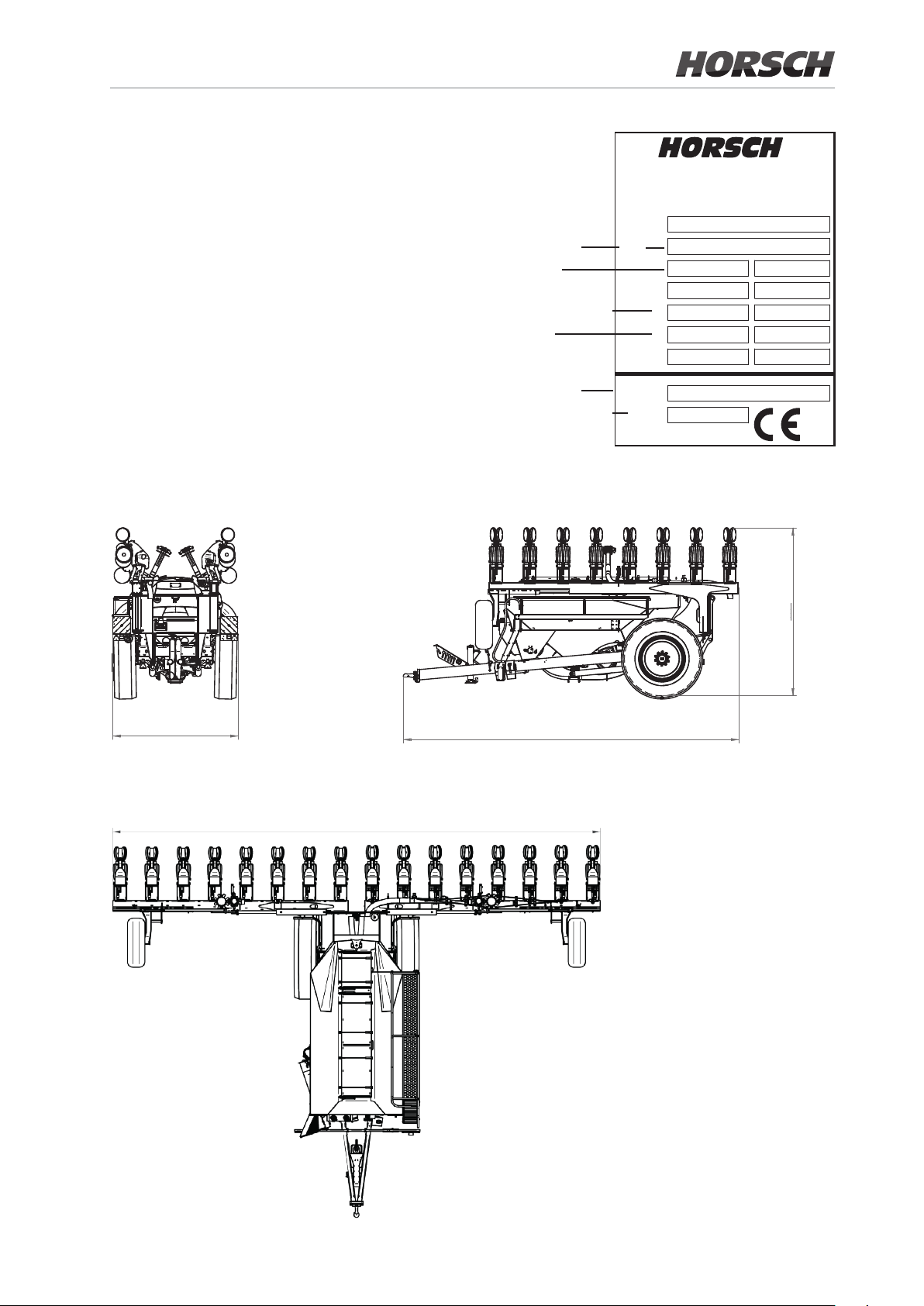
Type plate
70
a
b
e
Verlademaße Maestro 16.80 SW
3000
4000
8040
The type plate with the CE marking is located
on the frame of the machine.
Data on the type plate:
Serial number
Permissible
total weight
Drawbar load (= DL)
Axle load
HORSCH Maschinen GmbH
Sitzenhof 1, D-92421 Schwandorf
Tel. +49 (0) 9431 / 7143-0
Fax +49 (0) 9431 / 413 64
VIN
1
2
3
16.70 / 16.75 / 16.80 SW
3000
(Figure 16.80 SW)
11180 (16.70 SW) 11610 (16.75 SW) 12360 (16.80 SW)
Machine type
Year of construction
8060 (at 16.70 SW) / 8040 (at 16.75 SW and 16.80 SW)
Type
Baujahr
Made in Germany
4000
(Figure 16.75 SW)
21
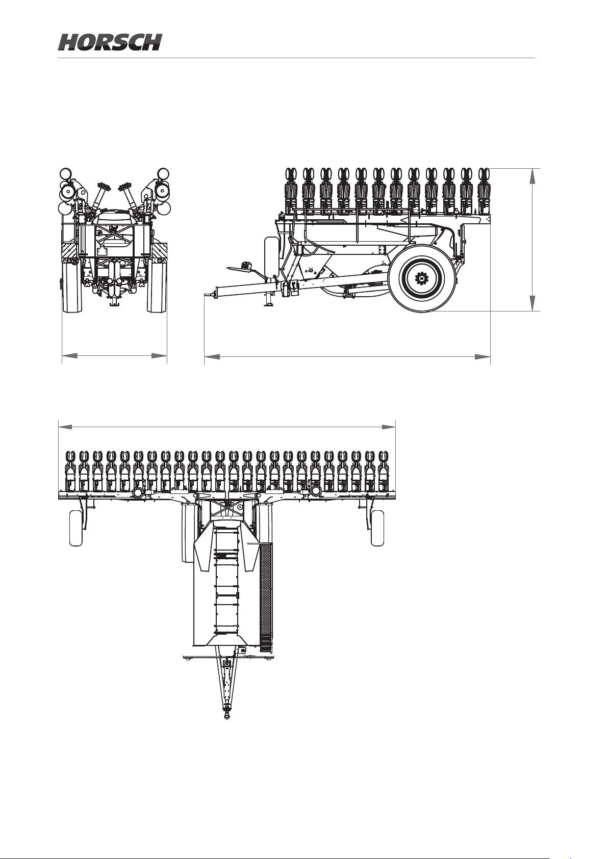
24.50 / 24.50 SW
3000 8170
4000
11150 (24.45 SW) / 12200 (24.50 SW)
22
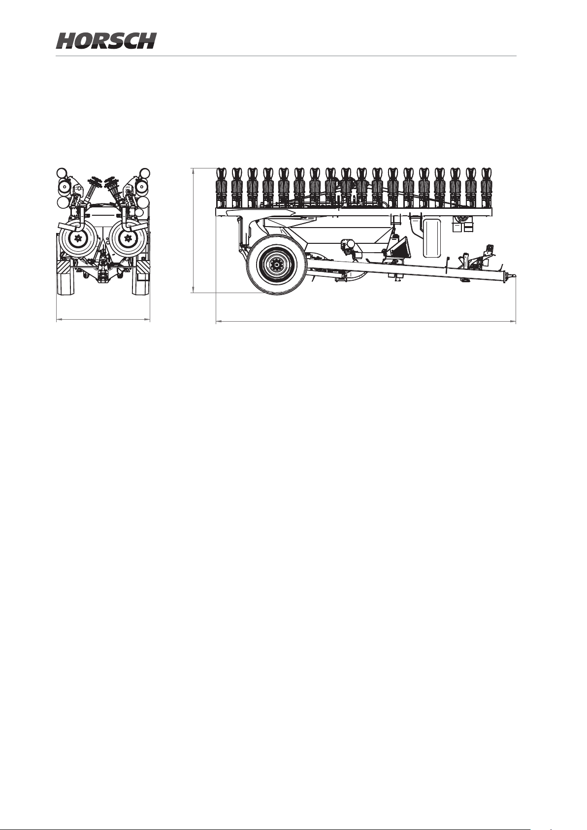
24.70 / 24.75 SW
Verlademaße Maestro 24.70 SW
2990
4000
9500
700
3000
(Figure 24.70 SW)
700 / 750
16460 (24.70 SW) 17610 (24.75 SW)
(Figure 24.75 SW)
23
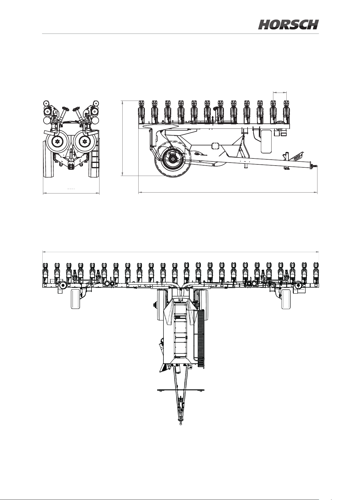
36 SW
4000
3000
9640 (36.45 SW) / 9620 (36.50 SW)
24

Requirements for the
tractor
WARNING
Risk of accident!
¾ Observe the permissible values of the tractor
for axle loads, total weight, tyre load bearing
capacity and air pressure.
¾ Verify the suitability of the tractor before com-
missioning.
The tractor must meet the following requirements to be able to use the machine as intended:
Implement attachment *
Maestro
Adjustable drawbar ø drawbar eye 58 mm
Ball head K 80
16 / 24 / 36 SW
ø drawbar eye 79 mm
Engine power
Maestro
from (kW / HP) 160 / 220 200 / 270 243 / 330
16 SW 24 SW 36 SW
Electrics / Control system
Maestro 16 SW 24 SW 36 SW
Current consumption during
operation
Electric power supply 12 V
50 A 60 A 80 A
Lighting
Control ISOBUS socket
Socket, 7-pin, see chapter Lighting
25

Hydraulics
Maestro 16 SW 24 SW 36 SW
Pressureless return ow (max. 5 bar) 1 1 1
Number of dual-acting control units
(direct drive equipment):
Hydraulic functions 1 1 1
Vacuum
(with adjustable ow rate)
Fertiliser
(with adjustable ow rate)
Seed
(with adjustable ow rate)
Filling auger 1 1 1
Number of dual-acting control units
(PTO-shaft drive equipment):
Hydraulic functions 1 1
Seed
(with adjustable ow rate)
Filling auger 1 1
Delivery rate at 180 bar
Fertiliser (l/min) 45 45 45
1 1 1
1 1 1
1 1 1
1 1
Seed (l/min) 20 20 20
Vacuum (l/min) 25
Maximum system pressure 210 bar
Oil grade Mineral hydraulic oil
26
24.45/50: 50
24.70/75/30″:
55
55
 Loading...