

horsch Leeb 8 GS, Leeb 6 GS, Leeb 7 GS Operating Instructions Manual

OPERATING INSTRUCTIONS
LEEB 6 / 7 / 8 GS
TRANSLATION OF THE ORIGINAL OPERATING INSTRUCTIONS
READ CAREFULLY PRIOR TO STARTING UP!
KEEP OPERATING INSTRUCTIONS IN A SAFE PLACE!
ART.:
ISSUE:
8090
09/2017
0221


- Translation of the Original Operating Instructions -
Machine Identication
The corresponding data is to be entered into the list below upon
receiving the machine:
Serial number: ..................................................
Machine type: ...................................................
Year of construction: ........................................
Initial installation: ..............................................
Fittings: .............................................................
..........................................................................
..........................................................................
..........................................................................
Publication date of Operation Manual:
Latest change:
Address of Retailer: Name: ......................................................................
Road: ......................................................................
Town/City: ......................................................................
Tel.: ......................................................................
Customer No.:
Retailer: ......................................................................
Address of HORSCH: HORSCH Maschinen GmbH
92421 Schwandorf, Sitzenhof 1
92401 Schwandorf, Postbox 1038
Tel.: +49 (0) 9431 / 7143-0
Fax: +49 (0) 9431 / 7143-9200
E-mail: info@horsch.com
Customer No.:
HORSCH: ......................................................................
09/2017
8090 21
LEEB 6 / 7 / 8 GS
02
en
Conrmation of receipt of machinery
Warranty claims become only eective when the rst use of the machine is reported to HORSCH
Maschinen GmbH within a week.
At www.horsch.com under SERVICE PARTNERBEREICH an interactive PDF form is available for down-
load for this purpose (not available in all languages).
By clicking on Send – depending on the email program installed – a mail draft with the completed
form is generated automatically. Alternatively, the form can be sent as email attachment to machine.
registration@horsch.com.
A dierent form of registration (postal mail, by fax, etc.) is not allowed for.
EG-Konformitätserklärung
Die
HORSCH LEEB Application Systems GmbH
Plattlinger Straße 21, D-94562 Oberpöring
erklärt hiermit in alleiniger Verantwortung als Hersteller, dass das nachfolgend genannte Produkt:
Maschine:
Typ:
Gezogene Pflanzenschutzspritze
Leeb 6 GS
Leeb 7 GS
Leeb 8 GS
den einschlägigen grundlegenden Sicherheits- und Gesundheitsanforderungen der Richtlinien
2006/42/EG und 2009/127/EG entspricht.
Oberpöring, 17.08.2017 Klaus Winkler
_________________________
Theodor Leeb
Geschäftsführer
Translation of EC Declaration of Conformity
(Directive 2006/42/EC)
Dokumentationsbevollmächtigter
HORSCH Maschinen GmbH
Sitzenhof 1
D-92421 Schwandorf
The manufacturer Horsch-Leeb Application Systems GmbH
Plattlinger Straße 21
D-94562 Oberpöring
hereby declares that the product
Machine designation:
Machine type:
this declaration refers to, conforms with all relevant fundamental health and safety requirements
of the EC directive 2006/42/EC.
Oberpöring, 17.08.2017 Klaus Winkler
Theodor Leeb
Managing director
Pulled crop protection sprayer
Leeb 6 GS
Leeb 7 GS
Leeb 8 GS
Documentation Representative
HORSCH Maschinen GmbH
Sitzenhof 1
D-92421 Schwandorf

Foreword
Please note:
Dear Customer,
We would like to thank you for the trust you have
expressed in us by buying this machine.
In order to be able to use the trailed crop
protection sprayer to your full advantage, please
read these operating instructions carefully
before using the machine.
These operating instructions contain important
information for the proper use and the safe
operation of the machine. By purchasing the
crop protection sprayer you have acquired a
quality product from HORSCH LEEB AS.
The trailed crop protection sprayer GS is a
machine sprayer for placing crop protection
agents and liquid fertiliser in compliance with
the statutory directives for soil cultures.
The contents of the operating instructions
is structured in such a way, that you will be
informed in detail about the required activities
in compliance with the work-related sequence.
The manual provides you with comprehensive
notes and information concerning maintenance,
safe use of the machine, safe working methods,
special precautions and available accessories.
Compliance with these notes and information is
necessary, important and useful for operational
safety, reliability and conservation of value of the
crop protection sprayer.
Always keep these operating instructions with
the crop protection sprayer. The operating
instructions are part of your machine.
HORSCH LEEB AS will not assume liability
for any damage or malfunctions resulting from
failure to comply with the operating instructions.
Upon delivery of the machine check for transport
damage or missing parts! Check the delivered
machine for completeness against the delivery
note, including optional equipment you have
ordered. Only immediately raised claims will
lead to compensation!
The operating instructions must be read and
strictly adhered to by all persons working on or
with the machine e.g.:
• Operation (including preparation, fault
rectication during work, care)
• Maintenance (maintenance, inspection)
• Transport
You receive an acknowledgement of receipt
together with the operating instructions. The
trained personnel of our service and sales
partners will train and instruct you in the
operation and care of your machine. After this
you or the sales or service partner should return
the receipt to HORSCH. This conrms your
formal acceptance of the machine.
The warranty period starts with the date of
delivery.
Only operate the machine after you have been
instructed and in full compliance with these
operating instructions. This crop protection
sprayer must only be used by persons who
are familiar with the machine and have been
informed about any possible dangers that may
arise from the machine.
Strictly follow the safety notes! Follow also
the applicable accident prevention regulations
as well as other generally recognised safety,
occupational health and road trac regulations.
5

Any information, illustrations and technical
specications in these operating instructions
are up-to-date at the time of publishing. We, at
any time, reserve the right for design changes,
technical and formal alterations to our products
for the purpose of improvement or to meet
changed legal regulations, without notication.
We will gladly make up-to-date data available
upon request.
Service
HORSCH LEEB AS wishes you to be fully
satised with your machine and us.
If you encounter any problems, please feel free
to contact your sales partner.
The service sta of our sales partners and the
service employees at HORSCH will always be
available to assist you.
Any directional statements made in these
operating instructions always refer to the travel
direction of the machine.
The illustrations in these operating instructions
show dierent versions of the implement and
dierent equipment variants.
In order to be able to solve technical problems
as quickly as possible, we ask you kindly to
support us.
Please help the service personnel by providing
the following information to avoid unnecessary
queries.
• Customer number
• Name of customer representative
• Name and address
• Machine model and serial number
• Purchasing date and operating hours or area
performance
• Type of problem
Compensation claims for damages that have
not occurred on the machine are excluded. This
also means that any liability for consequential
damages caused by travel and operating faults
is excluded.
Warranty claim processing
Warranty claim forms must be submitted through
your local HORSCH sales partner to the Service
Department of HORSCH LEEBG AS GmbH.
HORSCH LEEB Application Systems GmbH
Plattlinger Str. 21
D-94562 Oberpöring
Phone +49 (0) 99 37 . 95 96 30
Fax +49 (0) 99 37 . 95 96 366
www.horsch.com
All rights reserved
© 2015 HORSCH LEEB Application Systems GmbH
6

Table of contents
Foreword ......................................................5
1. Safety ....................................................... 11
1.1 Notes on representation ......................... 11
1.2 Qualication and training of personnel ... 11
1.3 Workplace of the operator ......................12
1.4 Danger caused by failing to comply
with the safety notes ...............................12
1.5 Safety conscious working .......................12
1.6 safety notices for the operator ................12
1.6.1 Safety and accident prevention
instructions .......................................12
1.6.2 Coupling and uncoupling the machine ....13
1.6.3 Working with the machine .................14
1.6.4 Changing equipment.........................14
1.6.5 Transporting the machine .................15
1.6.6 Hydraulic system ..............................15
1.6.7 Electric system ..................................16
1.6.8 Towed machines ...............................17
1.6.9 Brake system ....................................17
1.6.10 Pneumatic brake system ................17
1.6.11 Tyres ...............................................17
1.6.12 PTO-shaft / propshaft .....................18
1.6.13 Handling crop protection agents .....18
1.6.14 Operating the crop protection sprayer ...19
1.6.15 Maintenance ...................................20
1.7 Loading and unloading ...........................20
1.8 Unauthorized conversion and
manufacture of spare parts .....................21
1.9 Impermissible operating modes..............21
1.10 Spare parts and wear items as well
as auxiliary materials ............................21
1.11 Working in the vicinity of high
voltage power lines ...............................22
1.12 Phone and radio equipment .................22
1.13 Danger caused by residual energy .......22
1.14 Cleaning and waste disposal ................22
1.15 Intended use .........................................22
1.15.1 Specied equipment .......................23
1.15.2 Consequential damage ...................23
1.15.3 Eects when using certain crop
protection agents ............................24
1.15.4 Danger zones and danger points....24
1.15.5 Personal protective outt ................25
1.15.6 Organisational measures ................25
1.15.7 Operating instructions .....................25
1.16 safety notices on the machine ..............26
1.17 Instruction sticker..................................26
1.18 Safety stickers ......................................26
1.19 Position of safety stickers .....................29
2. Product description ................................31
2.1 Overview.................................................31
2.2 Safety and protective features ................32
2.3 Fluid circuit - Construction elements
on machines of the ECO variant .............33
2.4 Fluid circuit - Construction elements
on machines of the CCS variant ............34
2.5 Fluid circuit - Construction elements
on machines of the CCS Pro variant .....35
2.6 Supply lines between tractor and machine ....36
2.7 Trac-compliant equipment ...................36
2.8 Technical data .........................................37
2.8.1 Dimensions .......................................39
2.8.2 Permissible total weight and tyres ....40
2.9 Noise development data .........................44
2.10 Required tractor equipment ..................44
3. Design and function ...............................46
3.1 Control unit .............................................46
3.2 Connections............................................46
3.3 Folding boom ..........................................46
3.4 Nozzles ...................................................47
3.5 Spraying line ...........................................47
3.6 Spraying control......................................47
3.7 CCS - continuous inside cleaning...........47
3.8 Fluid circuit - function..............................48
3.9 Illuviation valve ......................................50
3.10 Spraying pump .....................................52
3.11 Piston diaphragm pump on machines
of the CCS Pro and CCS variant ..........52
3.12 Piston diaphragm pump on machines
of the ECO variant ...............................53
3.13 Hand washing tank ...............................53
3.14 Agitator .................................................54
3.15 Filter......................................................54
3.16 External cleaning system (optional)......55
3.17 Hydraulic connections ..........................56
3.17.1 Coupling hydraulic hoses ...............56
3.17.2 Uncoupling hydraulic hoses ...........57
3.18 Pulling tool (optional) ............................57
3.19 Lifting points .........................................58
7

3.20 Transport, document and safety
container ..............................................58
3.21 Document roll .......................................59
3.22 Pneumatic brake system ......................59
3.22.1 Automatic load dependent brake
pressure regulator (ALB) .................61
3.22.2 Connection of brake system ...........61
3.22.3 Uncoupling the brake system .........62
3.23 Drawbar ................................................63
3.24 Automatic Ackerman steering (optional) .... 63
3.24.1 Adjusting the mechanical
steering end stop .............................64
3.25 Trailing control on hillside locations
via manual control ................................64
3.26 Suspension ...........................................65
3.27 Hydraulic support..................................65
3.28 Working platform with ladder ................66
3.29 Fresh water tank ...................................66
3.30 Main control terminal ............................67
3.31 Multi-function handle ............................68
3.31.1 Default assignment of
multi-function handle ......................69
3.32 Propshaft ..............................................70
3.33 PTO-shaft pump (optional) ...................71
3.34 NightLight (optional) .............................72
3.35 Pack storage (optional).........................73
3.36 Hydraulic compressor ...........................73
3.37 GPS receiver (optional) ........................76
4. Design and Function of the
Spraying Boom ...........................................78
4.1 Folding boom control ..............................78
4.1.1 BoomControl Pro (optional) ..............78
4.1.2 BoomControl modes .........................79
4.2 Folding and unfolding .............................79
4.3 Folding variants - folding boom ..............81
4.4 Adjusting the spraying height..................82
4.5 Transport lock .........................................82
4.6 Slope compensation / pendulum lock .....84
4.7 Collision protection .................................84
4.8 Spraying line ...........................................85
4.8.1 Circulation system ............................85
4.8.2 Cleaning of nozzle pipe and nozzles ...85
4.9 Nozzle body ............................................86
4.9.1 Single nozzle body with
pneumatic control valve ....................86
4.9.2 Multiple nozzle body manual 3-fold ..86
4.9.3 Multiple nozzle body pneumatic........87
4.9.4 Multiple nozzle body manual 4-fold ..87
4.9.5 Border and edge nozzles, electric
(option) .............................................88
4.10 Nozzle assembly and cleaning .............90
4.10.1 Nozzle assembly .............................90
4.10.2 Nozzle replacement ........................90
4.10.3 Cleaning nozzles ............................90
4.10.4 Disassembling the diaphragm
valve in case of dripping nozzles ....90
5. Commissioning .......................................91
5.1 Check suitability of the tractor ................91
5.2 Safeguarding tractor / machine ..............92
5.3 Initial commissioning of the service
brake system..........................................93
5.4 Assemble the wheels ..............................93
5.5 Adjusting the hydraulic system on
the hydraulic valve block .........................93
6. Transport travels ....................................94
6.1 Safety notes............................................94
6.2 Shut-o valve ..........................................95
6.3 Transport lock .........................................96
6.3.1 Folding boom rest .............................96
6.3.2 Package lock ....................................96
6.3.3 Interlocking of slope compensation ....97
6.3.4 Interlocking of parallelogram.............97
7. Coupling and uncoupling the machine ...98
7.1 Coupling the machine .............................98
7.2 Uncoupling the machine .........................99
7.2.1 Manoeuvring the uncoupled machine ...100
8. Working with the machine ...................101
8.1 Preparing the spraying operation .........102
8.2 Preparing the spraying mixture.............103
8.2.1 Calculating lling / rell quantities ...105
8.2.2 Filling table for residual areas .........106
8

8.3 Filling with water ...................................107
8.3.1 Filling the spraying mixture
container through the lling port .....108
8.3.2 Direct lling / external lling (optional) ....109
8.3.3 Filling through the lling dome ........109
8.3.4 Filling the fresh water tank through
the ller connection ........................ 11 0
8.4 Flushing in preparations ....................... 111
8.4.1 Illuviation valve ............................... 111
8.4.2 Flushing in liquid preparations
during the lling process on
machines of the CCS Pro variant ... 112
8.4.3 Flushing in liquid preparations
during the lling process on
machines of the CCS variant .......... 11 3
8.4.4 Flushing in liquid preparations
during the lling process on
machines of the ECO variant.......... 11 4
8.4.5 Flushing in liquid preparations for
full or partly lled solution tank on
machines of the CCS Pro variant ... 115
8.4.6 Flushing in liquid preparations for
full or partly lled solution tank on
machines of the CCS variant .......... 11 5
8.4.7 Flushing in liquid preparations for
full or partly lled solution tank on
machines of the ECO variant.......... 11 6
8.4.8 Illuviation of powdery preparations
and carbonyl diamide on machines
of the CCS Pro variant.................... 11 6
8.4.9 Illuviation of powdery preparations
and carbonyl diamide on machines
of the CCS variant .......................... 117
8.4.10 Illuviation of powdery preparations
and carbonyl diamide on machines
of the ECO variant ......................... 117
8.4.11 Pre-cleaning the canister with
spraying mixture ........................... 118
8.4.12 Cleaning the canister with
fresh water .................................... 11 9
8.5 Spraying operation ...............................120
8.5.1 Special notes for spraying operation ... 120
8.5.2 Adjusting the spraying height ..........121
8.5.3 Spraying pressure, nozzle size,
placing quantity, travel speed,
agitator............................................121
8.5.4 Spraying ..........................................122
8.5.5 Measures for windward drift reduction ...122
8.5.6 Spraying with 25 cm nozzle
spacing and reduced target area
distance .........................................123
8.5.7 Emptying the spraying mixture
container via the pressure output ...123
8.6 Residual quantities ...............................124
8.6.1 Technical residual quantity ..............124
8.6.2 Eliminating residual quantities ........124
8.6.3 Draining of technical residual
quantities on machines of the
CCS Pro variant..............................125
8.6.4 Draining of technical residual
quantities on machines of the
CCS variant ....................................125
8.6.5 Draining of technical residual
quantities on machines of the
ECO variant ....................................126
8.6.6 Diluted residual quantities...............126
8.7 Draining the fresh water tank................127
8.8 Faults ....................................................128
9. Sprayer cleaning, maintenance...........129
9.1 Cleaning ...............................................131
9.1.1 CCS - Continuous inside cleaning
(Continuous Cleaning System) .......132
9.1.2 Cleaning the lters ..........................133
9.1.3 Cleaning the sprayer with
the tank empty ...............................135
9.1.4 Cleaning the sprayer with
the tank lled ..................................137
9.1.5 Folding boom cleaning with
“Air Valve” (option) ..........................138
9

10. Putting into storage ............................139
10.1 At the end of the spraying season ......139
10.2 Drainage .............................................139
10.2.1 Drainage of solution container ......139
10.2.2 Drainage of spraying pump...........139
10.2.3 Drainage of fresh water tank.........140
10.3 Putting the sprayer system in to
winter storage .....................................140
10.4 Before the new season .......................143
11. Maintenance and care plan ................144
11.1 Lubrication instructions .......................146
11.1.1 Overview of lubrication points
middle section................................147
11.1.2 Overview of lubrication points
spraying boom ..............................149
11.1.3 Overview of lubrication points
basic machine...............................150
11.2 Drawbar ..............................................152
11.3 High pressure cleaner (optional) .........152
11.4 Ball-and socket-coupling .....................153
11.5 Axle and brake ....................................154
11.5.1 General visual inspection ..............154
11.5.2 Axle adjustment (workshop work) ...155
11.5.3 Checking the wheel hub
bearing play (workshop work).......156
11.5.4 Replacing the grease of the
wheel hub bearing ........................156
11.5.5 Brake lining inspection ..................157
11.5.6 Brake adjustment ..........................157
11.5.7 Air vessel .......................................158
11.5.8 Test instructions for twin-line
brake system (workshop work) .....158
11.6 Tyres / wheels .....................................159
11.6.1 Air pressure in tyres ......................159
11.6.2 Assembling tyres (workshop work)....160
11.7 Maintenance – hydraulics ...................161
11.7.1 Identication of hydraulic hoses ....162
11.7.2 Maintenance intervals ...................162
11.7.3 Inspection criteria for hydraulic hoses ..162
11.7.4 Assembly and disassembly of
hydraulic hoses..............................163
11.7.5 Oil change PTO-shaft pump .........163
11.8 Calibrating the ow meter ...................164
11.9 Notes on crop sprayer test ..................165
11.9.1 Pump capacity test ........................165
11.9.2 Flow meter test .............................166
12. Nozzle selection..................................167
12.1 General ...............................................167
12.2 Procedure ...........................................167
12.2.1 With diagram and universal table ...167
12.2.2 With application quantity table ......170
12.3 Pressure ranges of dierent nozzles ...172
13. Liquid fertiliser operation ..................173
13.1 Conversion table for spraying
liquid fertiliser AHL .............................174
14. Waste disposal ...................................175
Appendix ...................................................176
Tightening torque ........................................176
Adjusting the propshaft ...............................178
Determine the operating lengths..............178
Shortening the propshaft .........................179
Index ..........................................................182
10

1. Safety
1.1 Notes on representation
Warning notes
These operating instructions distinguish between
three dierent types of warning notes.
The following signal words with warning
symbols are used:
DANGER
Highlights a danger that will lead to death or
severe injury if it is not avoided.
WARNING
Highlights a danger that may lead to death or
severe injury if not avoided.
CAUTION
Highlights a danger that may lead to injury if it
is not avoided.
Please read the warning notes given in these
operating instructions!
1.2 Qualication and
training of personnel
The crop protection sprayer must only be
operated, serviced and repaired by persons who
are familiar with it and have been made aware
of the dangers involved. The owner is obliged
to exactly specify the area of responsibility,
competence and the monitoring of personnel.
If the personnel do not have appropriate
knowledge, they must be trained and instructed
accordingly. A person being instructed must
only work with or on the machine under the
supervision of an experienced person.
The owner must further make sure that the
personnel has read and understood the contents
of these operating instructions.
Maintenance work not described in these
operating instructions must only be carried out
in authorized expert workshops.
Loading/
transport
Commissioning
Setup work
Operation
Person
specially
instructed for
the activity
Instructed
operator
Persons with
professional
training
Instructions
NOTE
Identies important notes.
Take-action instructions are indicated by arrow
points:
¾ ...
¾ Keep the order of the instructions. Alternatively,
instructions may be numbered consecutively.
The designations right, left, front and rear apply as
seen in travel direction.
Maintenance
Troubleshooting and
fault correction
Waste
disposal
*
NOTE
* Maintenance and repair work on the machine
must only be carried out by a specialist
workshop, if the related work is identied with
the sux “Workshop work”. Personnel in an
expert workshop have the necessary knowledge
and tools for professional and safe execution
of work.
11

1.3 Workplace of the operator
The machine must solely be operated by one
person and only from the driver's seat of the
tractor.
1.4 Danger caused by failing to comply with the safety notes
Follow the instructions given on the warning
signs to avoid dangers. The occupational safety
and accident prevention instructions issued by
the responsible liability association are binding.
When driving on public roads you must strictly
comply with the corresponding statutory
regulations (in the Federal Republic of Germany
the Road traffic licensing regulation and
Highway code).
When using public roads pay attention to the
relevant regulations!
Failing to comply with the safety notes can cause
danger to persons, but also the environment and
the machine. Moreover, it can lead to the loss
of all compensation claims.
In detail, failing to comply with the safety
regulations can lead to the following hazards:
¾ Danger to persons caused by unsecured
working areas
¾ Failure of important machine functions
¾ Failure of specied methods for service and
maintenance
¾ Danger to persons caused by mechanical and
chemical eects
¾ Danger to the environment caused by
hydraulic oil leaks
1.5 Safety conscious
Be prepared for emergencies. Always keep the
rst aid box close at hand.
Keep emergency numbers for physicians and
re ghters near the phone.
1.6 safety notices for the
operator
WARNING
Danger of crushing, cutting, being pulled in,
being caught and impact caused by missing
trac and operational safety.
Before each commissioning, check the machine
with respect to trac and operational safety!
1.6.1 Safety and accident
prevention instructions
working
The safety notes mentioned in these operating
instructions, any existing accident prevention
instructions and possibly existing internal work,
operating and safety instructions of the operator
must be strictly followed.
Besides the safety notices in these operating
instructions, the national and generally valid
occupational safety and accident prevention
instructions are also binding.
12
Besides the notices in these operating instructions
you should also pay attention to the generally
valid safety and accident prevention instructions!
¾ Before each commissioning of the machine
all safety and protective features must be
properly assembled and fully functional.
Check all safety and protective features at
regular intervals.
¾ The attached warning and information decals
provide important notes for safe operation.
Remember your safety!
¾ When using public roads pay attention to the
relevant regulations!
¾ Faulty or disassembled safety and protective
features can lead to dangerous situations.

¾ Become familiar with all equipment and
control elements as well as their functions
before starting work.
¾ It is prohibited to remain inside the working
range!
¾ Keep the machine clean and tidy to avoid
re hazards!
¾ Before drive o and before commissioning
check the immediate vicinity (children)!
Ensure sucient visibility!
¾ Couple the implements properly and fasten
and secure them only to the stipulated xtures!
¾ Pay attention to the permissible axle loads,
total weight and transport dimensions!
¾ Transport equipment, such as e.g. lighting,
warning facilities and possible protective
features must be checked and installed!
¾ Operating elements (ropes, chains, linkages,
etc.) for remote controlled devices must be
routed in such a way, that they will not trigger
unintended movements in any transport and
working positions.
¾ Make equipment t for road travel and lock as
specied by the manufacturer!
¾ Always match the speed to the ambient
conditions!
¾ Avoid sudden cornering when driving up and
down hill or across the slope!
¾ When driving on slopes – danger of tipping
over!
¾ Travel characteristics, steering and braking
ability are inuenced by attached or hitched
up equipment and ballasting weights. You
should therefore pay attention to sucient
steering and braking ability!
¾ Consider the overhang and/or centrifugal
mass of the machine when cornering!
¾ Only start operation of the machine after all
protective features have been installed and
are functional!
¾ Keep safety installations in good condition.
Replace missing or damaged parts.
¾ Using the machine for riding on or transporting
persons is prohibited!
¾ Do not remain in the turning and operating
range of the machine!
¾ The folding boom must only be operated when
there are no persons inside the slewing range!
¾ Parts actuated by external forces (e.g.
hydraulics) have crushing and shearing points!
¾ When working on the crop protection sprayer
secure the machine with wheel chocks
against rolling away!
¾ Match your travel mode in such a way, that
you will at any time be able to securely control
the tractor with hitched up or unhitched
machine at any time.
Be aware of your own abilities, account for the
road, trac, sight and weather conditions, the
driving characteristics of the tractor and the
inuences of the mounted or towed machine.
1.6.2 Coupling and uncoupling
the machine
¾ Couple the machine only to such tractors
and transport it with tractors suitable for this
purpose.
¾ Couple the machine properly to the specied
devices!
¾ By coupling the machine to the front and/or
rear of a tractor you must not exceed:
• the permissible total weight of the tractor
• the permissible tractor axle loads
• the permissible tyre load bearing capacities
of the tractor tyres
¾ Secure both tractor and machine against
unintended rolling away before coupling or
uncoupling the machine!
¾ Persons are not allowed to stand between the
machine to be hitched up and the tractor, while
the tractor is moving towards the machine!
Possibly assisting persons must stay besides
the vehicles and may only step between the
vehicles when these are at standstill.
¾ Lock the operating lever for the tractor
hydraulics in a position in which accidental
lifting or lowering is ruled out!
¾ When hitching and uncoupling machines
move the supporting devices (if present) to
the corresponding position (stability)!
13

¾ When operating supporting devices there is a
risk of injury at crushing and shearing points!
¾ Be particularly cautious when coupling and
uncoupling the machine to or from the tractor!
There are crushing and shearing points at the
coupling point between tractor and machine!
¾ Persons are not permitted to stand between
tractor and machine when the hydraulics are
operated!
¾ Coupled supply lines
• must easily follow all movements when
cornering without any tension, buckling or
chang.
• must not rub against other parts.
¾ Triggering ropes for quick release couplings
must hang down loosely and should not
trigger any action when in the lowest position!
¾ Always park unhitched machines in a stable
position!
¾ Never uncouple with an empty tank and
unfolded folding boom!
Negative drawbar load can cause the machine
to tip over!
¾ Never climb onto the moving machine!
¾ Parts actuated by external forces (e.g.
hydraulics) have crushing and shearing
points!
¾ Power operated machine parts must only be
actuated if persons keep a sucient safety
distance to the machine!
¾ Secure the tractor against unintended starting
and accidental rolling before leaving it.
To do so
• lower the machine to the ground
• apply the parking brake
• shut down the tractor engine
• Pull out the ignition key
NOTE
Machines operated via the ISOBUS of the
tractor are always active via terminal 15 of the
tractor, even when the machine terminal is
disabled!
1.6.3 Working with the machine
¾ Become familiar with all equipment and
control elements of the machine as well as
their functions before starting work.
¾ Wear tight fitting clothes! Loose clothes
increase the danger of being caught or pulled
in by rotating or moveable components.
¾ Only start operation of the machine, if all
protective features have been installed and
are fully functional in protective position!
¾ Observe the maximum payload of the mounted
/ hitched up machine and the permissible axle
and drawbar loads of the tractor! If necessary
drive with the tank only partly lled.
¾ Persons are not permitted to stay inside the
working range of the machine!
¾ Persons are not permitted to stay inside the
turning and slewing range of the machine!
1.6.4 Changing equipment
¾ Secure the machine against unintended
rolling away!
¾ Secure raised frame parts you have to work
under with suitable supports!
¾ Caution! Danger of injury caused by protruding
parts (boom parts, etc.)!
¾ Do not step on moving or other rotating parts
to climb onto the machine. You could fall and
be seriously injured.
¾ Use accessing aids and steps only at
standstill. During operation it is not permitted
to ride on the machine as a passenger!
14

1.6.5 Transporting the machine
¾ When driving on public roads comply with
the corresponding national road traffic
regulations!
¾ Before starting transport travels check the
correct connection of all supply lines:
• the light system for damage, function and
cleanliness
• the brake and hydraulic system for apparent
faults
• whether the parking brake is fully released
• the function of the brake system
¾ Always ensure sucient steering and braking
capacity of the tractor!
Machines attached to or towed by a tractor
or front or tail weights affect the driving
properties as well as the steering and braking
ability of the tractor.
¾ Observe the maximum payload of the mounted
/ hitched up machine and the permissible axle
and drawbar loads of the tractor!
¾ The tractor must secure the prescribed
braking deceleration for the load carrying
tractor/machine combination!
¾ Check the braking eect before setting o!
¾ Consider the width and centrifugal mass of
the machine when cornering with the machine
attached or hitched up!
¾ Before starting transport travels move all
pivotable machine parts into transport
position!
¾ Before starting transport travels lock all
pivotable machine parts in transport position
to prevent endangering position changes.
Use the dedicated transport locks for this
purpose!
¾ Before starting transport travels lock the
control levers for the hydraulics to prevent
accidental lifting or lowering of the attached
or hitched up machine!
¾ Before starting transport travels check
whether the necessary transport equipment
has been correctly mounted to the machine,
such as e.g. lighting, warning signs and
protective features!
¾ Match the travel speed to the prevailing
conditions!
¾ Shift to a lower gear before driving downhill!
¾ Always switch o single wheel braking (lock
the pedals) before starting transport travel!
¾ Pay attention to the notes in chapter Transport
travel.
1.6.6 Hydraulic system
WARNING
¾ The hydraulic system is under high pressure!
¾ Ensure correct connection of the hydraulic
hose lines!
¾ When connecting hydraulic hoses make sure
that the hydraulics has been depressurized
on both tractor and machine side!
¾ Blocking actuators on the tractor, which serve
the purpose of directly executing hydraulic or
electric movements of components, such as
e.g. folding, slewing and pushing processes,
is prohibited.
The corresponding movements must
automatically stop once you release the
corresponding actuator. This does not apply
to movements of equipment which
• are continuous or
• automatically controlled or
• require a floating or pressure position
because of their function
¾ Before starting work on the hydraulic system
• lower the machine to the ground
• depressurize the hydraulic system
• shut down the tractor engine
• apply the parking brake
• pull out the ignition key
15

¾ Pressure accumulator
Depending on the equipment the hydraulic
system may have a pressure accumulator
installed. Do not open or work (welding, drilling)
on the pressure accumulator. Even after being
emptied, the accumulator is still preloaded
by gas pressure. Always depressurize the
pressure accumulator before starting work on
the hydraulics. The pressure gauge (if present)
must not indicate any pressure. The pressure
in the pressure gauge must drop to 0 bar. Only
then may work be carried out on the hydraulic
system.
¾ Have the hydraulic hoses inspected by an
expert under occupational safety related
aspects at least once every year!
¾ Replace hydraulic hoses if damaged or
excessively aged! Use only genuine hydraulic
hoses from HORSCH LEEB AS!
¾ In order to avoid accidents caused by
undesired hydraulic movements or hydraulic
movements triggered by other persons
(children, passenger), the control units on the
tractor must be secured and locked when not
in use or in transport position.
1.6.7 Electric system
Always disconnect the battery (negative pole)
before starting work in the electric system!
¾ Use only the specied fuses. The use of fuses
with the rating too high will destroy the electric
system. Fire hazard!
¾ Make sure that the battery is correctly
connected. Connect the positive pole rst and
the negative pole after! When disconnecting
disconnect the negative pole rst and the
positive pole after!
¾ The utilization period of hydraulic hoses
should not exceed six years, including a
possible storage time of maximum two years.
Even if properly stored and under permissible
stress, hoses and hose connections are
subject to natural ageing, which limits their
shelf life and utilization period. Deviating
from this, the utilization period can also be
determined on the basis of empirical values,
particularly under due consideration of the
endangering potential. For hoses and hose
lines made of thermoplastics other guide
values may be decisive.
¾ Never try to seal o leaking hydraulic hoses
with your hands or ngers. Fluids (hydraulic
oil) escaping under pressure can penetrate
the skin and enter into the body causing
severe injury! If injured by hydraulic oil,
consult a doctor immediately! Danger of
infection!
¾ Due to the possible danger of severe infections,
one must use appropriate auxiliary means
when looking for leakages!
¾ Power sockets and connectors (electric,
pneumatic) should be identied by colour to
rule out operating errors.
¾ Always cover the positive battery pole with the
dedicated covering. Danger of explosion in
case of short-circuit to ground!
¾ Avoid sparking and naked flames in the
vicinity of the battery. Danger of explosion!
¾ The machine can be equipped with electronic
components and parts, the function of which
may be affected by the transmission of
electromagnetic waves from other equipment.
Such inuences may put persons in danger,
if the following safety notes are not complied
with.
In case of a subsequent installation of
electric appliances and/or components on
the machine, with connection to the on-board
power supply, the user is responsible for
checking whether this installation will cause
faults in the vehicle electronics or in other
components.
Make sure that the subsequently installed
electric and electronic components are
in accordance with the valid issue of the
EMC directive 2014/30/EC and are identied
with the CE-sign.
16

1.6.8 Towed machines
1.6.10 Pneumatic brake system
¾ Pay attention to the permissible combinations
of hitching device on the tractor and drawbar
hitch on the machine!
Couple only permissible vehicle combinations
(tractor and towed machine).
¾ In case of single-axle machines pay attention
to the maximum permissible drawbar load of
the tractor on the hitching device!
¾ Always ensure sucient steering and braking
capacity of the tractor!
Machines mounted to or towed by a tractor
aect the travel behaviour as well as the
steering and braking ability of the tractor,
especially single-axle machines with drawbar
load applied to the tractor!
¾ For drawbars with drawbar load, the height
of the drawbar must only be adjusted in a
specialist workshop!
1.6.9 Brake system
¾ Only drive o with the hitched up machine
after the operating pressure required to
release the brake has been reached (pressure
gauge on tractor).
¾ Before coupling the machine clean the seal
rings on the coupling heads of the supply and
brake line from possible contamination!
¾ Close the coupling heads on the tractor before
driving without machine!
¾ Close the coupling heads of supply and
brake lines and hook these into the brackets
provided for this purpose!
¾ Drain the air vessel daily!
¾ The specied settings on the brake valves
must not be changed!
¾ Change the air vessel if it is loose in the
tension straps, if it is damaged, the type plate
is corroded, lose or missing.
1.6.11 Tyres
¾ Adjustment and repair work on the brake
system must only be carried out in expert
workshops or established brake service
workshops!
¾ Immediately stop the tractor in case of brake
system malfunctions.
Have the malfunction remedied immediately!
¾ The brake system must be thoroughly
checked at regular intervals!
¾ Securely park the machine before starting
work on the brake system. Secure the
machine against unintended lowering and
rolling away (wheel chocks)!
¾ Be extra careful when performing welding,
ame cutting or drilling work near brake lines!
¾ After setup and repair work on the brake
system you must generally carry out a brake
test!
¾ Pay attention to the corresponding regulations
(France) when changing the hydraulic oil!
¾ Only use the specied hydraulic oils (France)
when topping up or changing the hydraulic oil.
¾ When working on the tyres make sure that the
machine has been parked safely and properly
secured against rolling away and accidental
lowering (parking brake, wheel chocks).
¾ The assembly of wheels and tyres requires
adequate knowledge and the use of proper
assembly tools!
¾ Repair work on tyres and wheels must only
be carried out by specialists and only with the
appropriate assembly tools for this kind of work!
¾ Check the air pressure regularly! Pay attention
to the specied air pressure!
¾ Check the wheel nuts regularly and retighten
all fastening screws and nuts as specied by
HORSCH LEEB AS GmbH! Failing to do so
can lead to loosing wheels and thus to the
machine tipping over.
17

1.6.12 PTO-shaft / propshaft
Persons can be caught, pulled in and seriously
injured by the rotating PTO-shaft or propshaft.
Before any work on the propshaft (assembly,
dismantling, etc.):
¾ Uncouple the PTO-shaft (disable it from the
tractor’s cab).
¾ Switch o the tractor engine.
¾ Pull off the ignition key and wait until all
moving parts have stopped.
Before switching on the PTO-shaft:
¾ Make sure that the PTO-shaft guard is in place
and functional.
¾ Make sure that the chosen rotary speed and
the sense of rotation of the propshaft or PTOshaft correspond with the permissible values
for the machine.
¾ Make sure that no persons are inside the
danger zone around the PTO-shaft or
propshaft.
¾ Never switch on or couple the PTO-shaft while
the tractor motor is shut down.
¾ Shut down the PTO-shaft if the angles are too
large. The machine could become damaged.
Parts may be thrown o and injure persons.
¾ Switch o the PTO-shaft if it is no longer
needed.
¾ Ensure sucient overlapping of prole tube
and PTO-shaft guard.
¾ Allow PTO-shaft locks to click into place.
¾ Secure the PTO-shaft guard with chains
against rotating.
¾ Follow the operating instructions for the
propshaft.
1.6.13 Handling crop protection
agents
¾ Follow the recommendations of the crop
protection agent manufacturers in regard to
• protective clothing.
• Warnings concerning the handling of crop
protection agents.
• Regulations for metering, use and cleaning.
¾ Store all relevant information about the used
crop protection agent (safety data sheets,
instructions for use, etc.) in the document
container.
¾ Pay attention to the notes in the “AID”
publications - No. 1237 “Crop protection
terminology” and No. 1042 “Caution when
handling crop protection agents”. (Only
available in German)
¾ The water quality (the water hardness and
mineral content in particular) inuences the
property of some fertilisers and crop protection
agents. Precipitation and deocculation can
cause deposits in lters and nozzles.
Example: Extremely hard water reacts with
sulphate-bearing fertiliser to form calcium
sulphate (gypsum) and causes white deposits
in the lters.
Pay attention to the conditions of use and
the combination possibilities given by the
corresponding manufacturers to avoid such
problems!
¾ Observe the data on compatibility of crop
protection agents with materials of the crop
protection sprayer!
¾ Do not spray any crop protection agents
that have a tendency to agglutination or
solidication!
¾ Wear suitable protective clothing when
handling crop protection agents.
¾ Do not eat, drink or smoke while handling crop
protection agents!
¾ Keep crop protection equipment and crop
protection agents out of the reach of children!
¾ Always ensure a sucient water supply in the
machine to be able to wash o crop protection
agent in the event of an emergency.
¾ In case of physical contact with crop protection
agents you may need to consult a physician.
¾ Thoroughly clean hands and face after the
end of work.
18

1.6.14 Operating the crop
protection sprayer
¾ Pay attention to the notes in the Plant
Protection Act!
¾ Observe the notes in the publications of the
“Federal Ministry for food, agriculture and
consumer protection”.
¾ Never open pressurized lines!
¾ Use only original spare hoses from HORSCH
LEEB AS, which will withstand the chemical,
mechanical and thermal loads. For assembly
you should generally use hose clamps made
of V2A!
¾ Please pay attention to the following when
repairing crop protection sprayers which have
been used with ammonium nitrate - carbonyl
diamide solution:
residues of ammonium nitrate - carbonyl
diamide solution can be form salt on or inside
the spraying mixture container through the
evaporation of water. This results in pure
ammonium nitrate and carbonyl diamide. In
its pure form, ammonium nitrate in connection
with organic matter, such as carbonyl diamide,
becomes explosive, if critical temperatures
(caused by e.g. welding work, grinding, ling)
are reached during repair work.
¾ By thoroughly washing off the spraying
mixture container or the parts to be repaired
with water, this risk can be eliminated,
because the salt of the ammonium nitrate carbonyl diamide solution is water soluble.
Therefore always clean the crop protection
sprayer thoroughly with water before starting
repair work!
¾ The rated volume of the spraying mixture
container must not be exceeded when lling!
¾ At the headland reduce the travel speed and
switch o the sprayer.
¾ Excessive, jerky steering movements at the
beginning and the end of a curve will put
extreme loads on the folding boom.
¾ When applying small droplets under strong
wind, the chemical can be blown about and
thus cause damage to others!
¾ If the soil is very dry, the applied chemical
can be blown away together with dust and
cause damage. Always wait until the soil is
suciently moist!
¾ Check the following from time to time:
Metering quantity, clogged nozzles, damage
to machine parts, leakage and cleanliness of
the machine.
¾ For tractors with cabins with ventilation fans
replace the fresh air lters with activatedcarbon lters!
¾ Ensure that the category of the tractor cabin
is approved for the respective crop protection
agent used.
¾ Do not ll crop protection sprayers with water
from open bodies of water - to protect man,
animal and environment!
¾ Always ensure a sucient water supply in the
machine to be able to wash o crop protection
agent in events of emergency.
¾ When using these preparations strictly
comply with the instructions for use and
the precautions listed issued by the crop
protection product manufacturer!
¾ Data concerning the preparations used must
always be kept in the transport box, so that
these are available for rescue services in case
of accidents.
¾ Fill the crop protection sprayer only through
original HORSCH LEEB AS lling equipment
and by gravity feed via the water mains!
¾ Never blow out nozzles and other small parts
with your mouth.
¾ Thoroughly clean hands and face after the
end of work.
19

1.6.15 Maintenance
WARNING
Danger of poisoning - Do not climb into the
spraying mixture container!
Only trained personnel with suitable protective
outt and securing devices may climb into the
tank for cleaning.
¾ Wear gloves to protect against sharp-edged
machine parts.
¾ Repair, maintenance and cleaning work as
well as the rectication of malfunctions must
generally be carried out with the engine shut
down! Pull the machine plug o the on-board
computer. Pull out the ignition key!
¾ Before starting maintenance work clean the
crop protection sprayer, especially all parts
which are contaminated by spraying mixture.
¾ Repair work inside the spraying mixture
container must only be performed after
thorough cleaning and with a respirator. This
work must be monitored by a second person
outside the spraying mixture container for
safety reasons! Ensure sucient ventilation
of the spraying mixture container!
¾ Perform all specied adjustment, maintenance
and inspection tasks as scheduled.
¾ Secure all operating media like compressed
air and hydraulics against unintended
commissioning.
¾ Secure the raised machine or raised machine
parts against accidental lowering before
starting maintenance, repair and cleaning
work!
¾ Safely take up and fasten large assembly
groups with lifting gear for replacement.
¾ Check nuts and screws regularly for tight t
and retighten as necessary!
¾ When exchanging cultivation tools use
appropriate tools and wear gloves!
¾ Dispose of oils, greases and lters according to
applicable regulations!
¾ Prior to working on the electrical system,
disconnect it from the electric current supply!
¾ Disconnect the cable from the generator
and the battery of the tractor before starting
electric welding work on tractor or connected
machines!
The ground connection must be as close as
possible to the welding point.
¾ If protective features are subjected to wear,
they must be inspected at regular intervals
and replaced in due time
¾ Spare parts must at least meet the technical
requirements specified by the equipment
manufacturer! This is ensured when using
original spare parts from HORSCH LEEB AS!
¾ For the storage of gas use only nitrogen for
lling - danger of explosion!
1.7 Loading and
unloading
WARNING
Danger of accident when using an inappropriate
tractor and if the brake system of the machine is
not connected with the tractor or not lled!
Couple the machine properly to the tractor
before the machine is loaded onto or off a
transport vehicle!
For loading and unloading the machine couple
it only to a tractor and transport it with a tractor
that meets the specied power requirements!
NOTE
Only start to drive o with the coupled machine
after the operating pressure required to release
the pneumatic brake system has been reached
(pressure gauge on tractor).
20

1.8 Unauthorized
1.9 Impermissible
conversion and
manufacture of spare
parts
WARNING
Danger of crushing, cutting, being caught,
being pulled in and impact caused by the
breakage of load bearing components.
The following is generally prohibited:
¾ drilling in frame and undercarriage
¾ enlargement of existing bore holes on frame
and undercarriage
¾ welding on load bearing parts
Conversions or changes to the machine are only
permitted in agreement with the manufacturer.
Original spare parts and authorized accessories
serve your safety.
This also applies for welding work on load
bearing components.
The use of parts other than the ones specied
may result in the rejection of liability for resulting
damage.
Use only conversion and accessory parts
approved by HORSCH LEEB AS GmbH, e.g. to
maintain the validity of the type approval as per
national and international regulations.
operating modes
The operational safety of the delivered machine
is only ensured in case of intended use as
specied in the operating instructions.
The limit values specied in the data sheets must
under no circumstances be exceeded.
1.10 Spare parts and wear
items as well as auxiliary
materials
Machine parts in unacceptable condition
must be replaced immediately.
Use only original HORSCH LEEB AS spare parts
and wear items, to maintain the validity of the
type approval as per national and international
regulations.
When using spare parts and wear items from
third parties it cannot be ensured that these
have been designed and manufactured under
the aspects of expected loads and safety.
HORSCH LEEB AS GmbH does not assume
liability for damage resulting from the use of
unapproved spare parts and wear items or
auxiliary materials.
The following machines must be in a condition
that is determined by the corresponding
acceptance or approval:
¾ vehicles with a governmental type approval
¾ implements and equipment connected with
a vehicle with a valid type approval or an
approval for road trac.
21

1.11 Working in the
1.13 Danger caused by
vicinity of high voltage
power lines
Use extra caution when working under or within
the range of high voltage power lines.
WARNING
Danger of electric accidents by touching high
voltage power lines or voltage transfer via the
spraying boom!
¾ The total height of 4 m can also be considerably
exceeded during eld work. This can occur
with lifted parallelogram and simultaneously
angular actuated folding boom wings.
Assess the situation before starting work.
¾ If you have to pass under overhead lines, you
must ask the operator of these overhead lines
about their rated voltage and minimum height.
¾ The safety distances specied in the table
must under no circumstances be fallen short
of.
Rated voltage Safety distance from
overhead lines
residual energy
Pay attention to the occurrence of mechanical,
hydraulic, pneumatic and electric/electronic
residual energies on the machine. Apply
appropriate measures when instructing
operating personnel. You will nd detailed notes
in the corresponding chapters of the operating
instructions.
1.14 Cleaning and waste
disposal
Handle and dispose of all materials and
substances used for this purpose appropriately
(see chapter “Waste disposal of crop protection
sprayer”), especially when working on lubrication
system and facilities and when using solvents
for cleaning.
NOTE
Do not clean new machines with a steam jet of a
high pressure cleaner. The paint takes approx.
3 months to cure and could be damaged before
this time.
[kV] [m]
up to 1 1
1 to 110 2
110 to 220 3
220 to 380 4
1.12 Phone and radio
equipment
Phones and radio equipment not connected to
an external aerial may disturb the function of
the vehicle electronics and thus endanger its
operational safety.
1.15 Intended use
Use of the crop protection sprayer is considered
as intended if the following points are accounted
for during operation of the machine. The
manufacturer is not liable for damages from
unintended use. The risk will be borne solely
by the user.
¾ The crop protection sprayer is intended for
the application of crop protection agents
(insecticides, fungicides, herbicides, etc.) in
form of suspensions, emulsions and mixtures
as well as of liquid fertilisers.
¾ The sprayer is solely intended for agricultural
applications in the treatment of plantations. It
is compliant with the latest technical standard
and, when correctly set and adjusted and with
the correct metering, it ensures biological
success.
22

¾ The machine must only be operated for
its intended use if in a technically perfect
condition, whilst being aware of safety
and risks and in strict compliance with the
operating instructions.
¾ The working machine is operated by one
person sitting in the cabin.
¾ The crop protection sprayer is a working
machine, which must only be driven on public
roads in strict compliance with the permitted
axle loads.
¾ Any faults that could adversely affect
operational safety must be eliminated
immediately!
¾ Defective or excessively strained parts must
be replaced immediately. The machine must
otherwise not be operated.
¾ Use only genuine HORSCH-LEEB-AS spare
parts for repairs. Other spare parts have
not been tested and approved by HORSCH
LEEB AS and may have a negative inuence
on machine characteristics or severely aect
the safety.
¾ Changes to the machine, which may have a
negative eect on safety, are only permitted
with the consent of the manufacturer.
The equipment is suitable for terrain sloping in
¾ Layer line
travel direction to the left 15 %
travel direction to the right 15 %
¾ Slope line
Uphill 15 %
Downhill 15 %
For damage caused by unintended use
¾ the owner shall be solely responsible!
¾ HORSCH LEEB AS GmbH will not assume
any liability.
1.15.1 Specied equipment
The specied equipment of the crop protection
sprayer results from the combination of
¾ Basic equipment and undercarriage
¾ Tyres
¾ Drawbar
¾ Pressure tting
¾ Pump equipment
¾ Spraying boom
¾ Spraying lines with section control and
optional equipment
Should one of our sales offices create an
individual type, that is not listed hereunder,
the sales oce in question is obliged to issue
the declaration required by § 25 of the plant
protection act from 15/09/1986, to the Julius
Kühn Institute.
The forms required for this purpose are available
from:
Julius Kühn Institute
Federal Research Institute for Crops
Messeweg 11/12
D-38104 Braunschweig
1.15.2 Consequential damage
Intended use also includes:
¾ paying attention to all notes in these operating
instructions.
¾ compliance with the specied inspection and
maintenance work.
¾ the sole use of genuine HORSCH LEEB AS
spare parts.
Any use different than described above is
prohibited and is considered unintended.
The machine has been manufactured by
HORSCH LEEB Application Systems GmbH
with great care. However, despite the intended
use deviations in placing quantity up to total
failure may be caused by e.g.:
¾ dierent compositions of crop protection agents
(insecticides, fungicides, herbicides etc.) in the
form of suspensions, emulsions and mixtures as
well as liquid fertilisers
¾ blockages and bridging (e.g. agglutination or
occulation of crop protection agents)
¾ wear of wear items
23

¾ damage caused by external eects (e.g.
ow meter)
¾ mechanical damage (e.g. pump defects)
¾ incorrect placing quantities and travel speeds
¾ incorrect sprayer settings and non-compliance
with the "Good professional practice in crop
protection - fundamentals for execution"
¾ reaction of crop protection agents caused by
impermissible mixing of two or more dierent
crop protection agents (e.g. occulation of the
spraying mixture)
1.15.4 Danger zones and danger
points
The danger zone is the area around the machine,
in which persons could be reached
¾ by work related movements of the machine
and its cultivation tools
¾ by materials or foreign objects thrown out of
the machine
¾ accidentally lowering or lifted cultivation tools
¾ unintended rolling of the vehicle
1.15.3 Eects when using certain
crop protection agents
At the time the crop protection sprayer is
manufactured the manufacturer is aware of only
a few approved crop protection agents approved
by the Julius Kühn Institute, which could have
a damaging eect on the materials used in the
crop protection equipment.
We would like to point out, that e.g. crop
protection agents known to us, such as Lasso,
Betanal and Tramal, Stomp, Iloxan, Mudecan,
Elancolan and Teridox will cause damage to
hoses and switching diaphragms, if these are
exposed to such products over a longer period
of time (20 hours). The listed examples do not
claim completeness.
We particularly warn against the use of non-
permitted mixtures of two or more dierent crop
protection agents. Substances with a tendency
to agglutination or solidication must not be
placed.
When using such aggressive crop protection
agents it is highly recommended to spray these
immediately after the preparation of the spraying
mixture and thoroughly clean the system with
water after.
The materials and components used for the
HORSCH LEEB AS crop protection sprayers
are liquid fertiliser proof.
The area marked red indicates the danger zone
of the machine:
The danger zone of the machine contains
dangerous spots with permanently existing or
unexpected dangers. These danger spots are
marked with warning signs, which warn against
residual dangers that cannot be technically
eliminated by design. In these cases the special
safety regulations in the corresponding chapters
do apply.
No persons are to remain within the danger zone
of the machine,
¾ as long as the tractor engine is running with
the hydraulic system connected.
¾ as long as tractor and machine have not been
secured against unintended starting and
accidental rolling away.
The operator must only move the machine
or change cultivation tools from transport to
working position and vice-versa or drive these
implements, if the danger zone of the machine
is free of persons.
24

Danger spots exist:
Wear safety gloves:
¾ between tractor and crop protection sprayer,
especially when coupling and uncoupling
¾ in the area of moving components.
¾ on the driving machine.
¾ in the slewing range of the spraying boom.
¾ in the spraying mixture container due to toxic
vapours.
¾ under the raised but unsupported machine or
parts of the machine.
¾ when unfolding and folding the spraying boom
in the area of overhead lines by contacting
such power lines.
1.15.5 Personal protective outt
WARNING
Health hazards caused by accidental contact
with crop protection agents or spraying
mixture!
¾ before you start to process crop protection
agents,
¾ before starting work on the contaminated crop
protection sprayer or
¾ before cleaning the crop protection sprayer.
Wash your safety gloves o with clear water
from the fresh water tank:
¾ immediately after any contact with crop
protection agents
¾ before taking o the protective gloves.
NOTE
Do not enter the tractor cabin with
contaminated protective outt!
Take o the protective outt and store it
in the stowage box of the crop protection
sprayer.
Wear personal protective outt:
¾ when preparing the spraying mixture
¾ when cleaning / replacing the spray nozzles,
during spraying operation, during all work
to clean the crop protection sprayer after
spraying operation.
When wearing the required protective clothing
you should always follow the information of
the manufacturer, the product information, the
instructions for use, the safety data sheet or the
operating instructions for the crop protection
agent to be used.
Required equipment:
¾ gloves resistant to chemicals
¾ overall resistant to chemicals
¾ waterproof shoes
¾ face protection
¾ respirator
1.15.6 Organisational measures
NOTE
The owner must provide the necessary personal
protective outt as specied by the manufacturer
of the crop protection agent to be applied.
1.15.7 Operating instructions
¾ The operating instructions must always be
kept near the place of use of the machine!
¾ The operating instructions must always be
freely accessible for operator and maintenance
personnel!
NOTE
Check all existing safety features at regular
intervals!
¾ safety goggles
¾ skin care agent, etc.
25
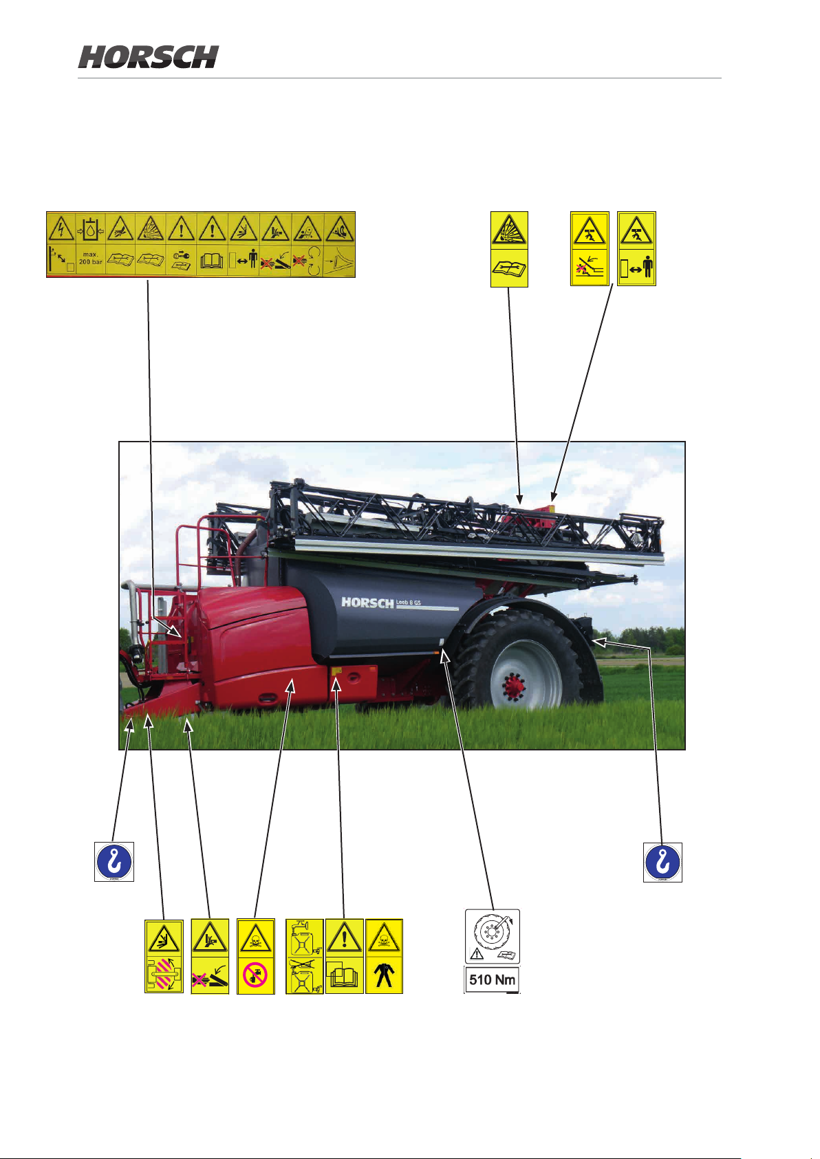
1.16 safety notices on the machine
The towed crop protection sprayer GS is
equipped with safety and protective features.
Not all danger spots on this machine can
be completely safeguarded under due
consideration of the functionality of the machine.
Corresponding safety notes on the machine
point to still remaining residual risks.
The danger notes are applied in the form of
warning signs or safety stickers.
Their position and meaning is shown next!.
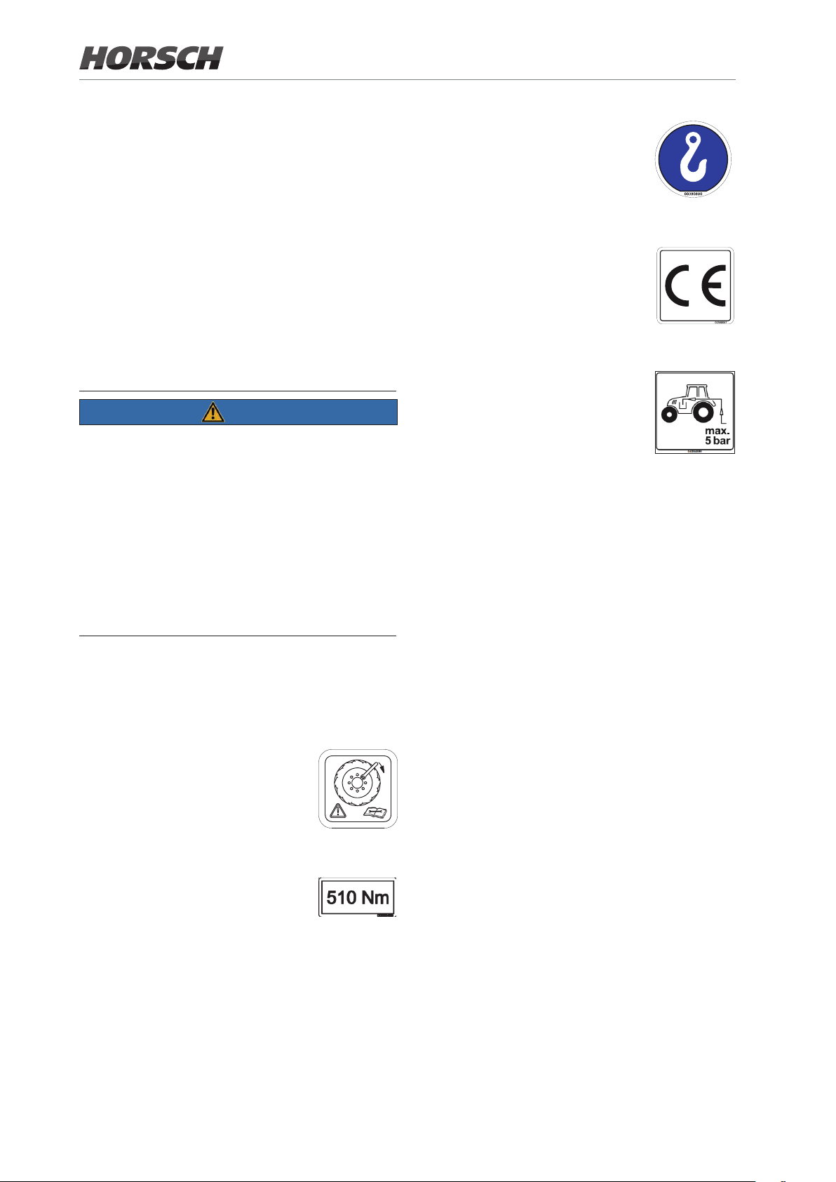
NOTE
Loading hook
hook the load suspension gear
(chains, ropes etc.) into this loading
hook during loading.
00380880
The CE-sign indicates that the
machine complies with the basic
health and safety requirements!
00380067
The return pressure of the hydraulics
from the crop protection sprayer to
the tractor must not exceed 5 bar.
Become familiar with the meaning of the
adjacent warning signs.
The opposite texts and the attachment
location on the machine provide information
about the special danger spots on the
machine.
Keep all warning signs on the machine in
clean and legible condition. Replace illegible
warning signs!
1.17 Instruction sticker
Check and retighten wheel nuts or
wheel bolts at regular intervals see maintenance overview!
00380359
00380359
04004899
1.18 Safety stickers
Safety stickers on the machine warn of hazards
at dangerous points and are an important part
of the safety equipment of the machine. Missing
safety stickers increase the risk of severe or
even fatal injuries.
¾ Clean soiled safety stickers.
¾ Damaged or illegible safety stickers must be
replaced immediately.
¾ Ax the specied safety stickers on spare
parts.
Tightening torque for wheel studs /
wheel nuts - 510 Nm
26
00385489
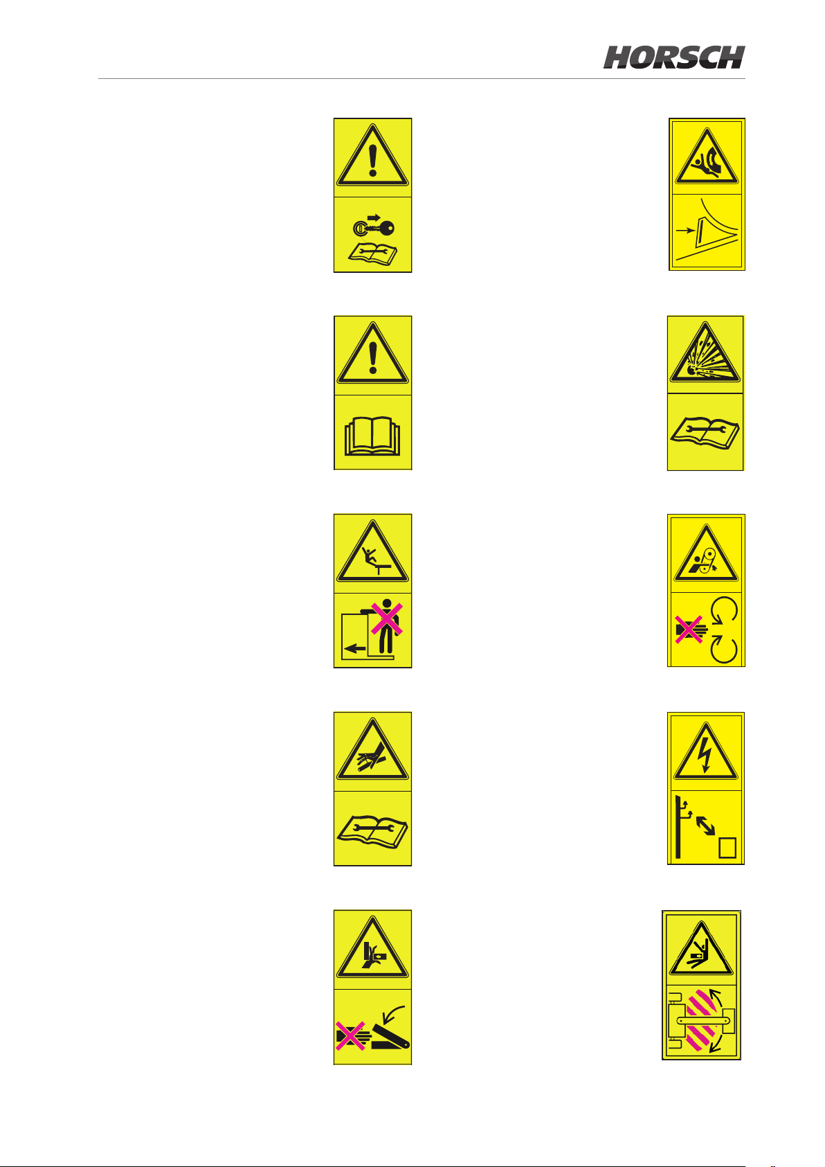
Switch the engine o and pull out
the key before starting maintenance
and repair work!
Danger caused by accidental
movement of the machine!
Before commissioning the machine
you need to read and follow
the operating instructions!
No passengers are allowed to ride
on the machine!
04002983
04002983
04001455
04002983
The pressure accumulator is
charged with gas or oil pressure.
Dismantle and repair only in strict
compliance with the instructions in
the technical manual!
04001679
Do not open or remove protective
features while the engine is running!
04002983
Take care of emerging high
pressure uid. Follow the notes in
the operating instructions!
Never reach into areas where there
is a risk of crushing as long as parts
could still be moving!
04002983
04001683
Keep sufficient distance to
electric high voltage power lines!
04002983
Staying in the operating range of
the drawbar between tractor and
towed machine is prohibited!
04002622
27
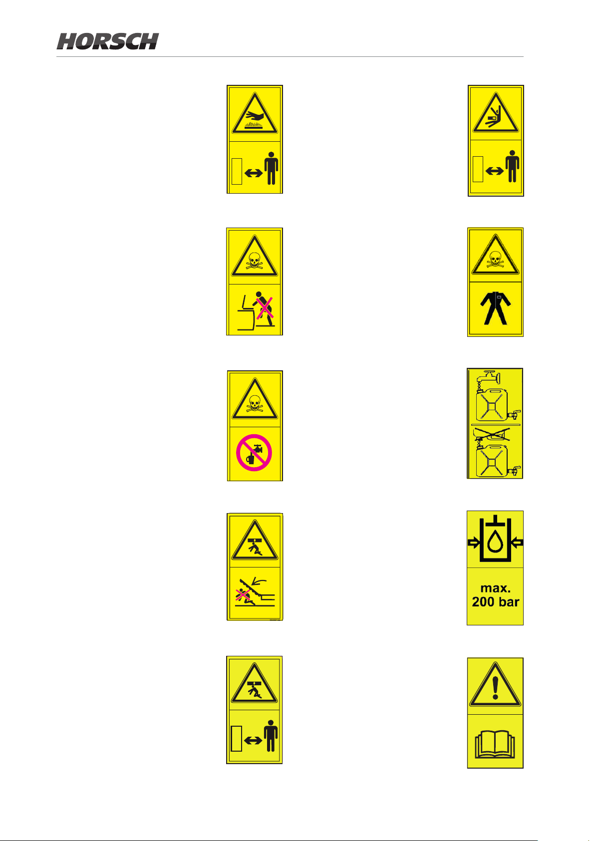
Danger of burning on hot surfaces.
Keep a safe distance to hot surfaces!
Keep a sucient safety distance to
the slewing range of the machine!
Danger of poisoning - never climb
into the tank!
Danger from inhaling hazardous
substances!
Danger of poisoning - no drinking
water!
04001453
04001456
04002623
04001454
Avoid any contact with hazardous
substances!
Wear protective clothing!
04003745
Fill the hand washing tank only with
clear water!
04002628
Do not stand in the slewing range
of the machine!
Do not stand inside the range of a
lifted but unsecured load!
04002625
04002626
The maximum operating pressure
in the hydraulic system is 200 bar.
04002983
Before commissioning the machine
you need to read and follow the
operating instructions!
i
04003747
28
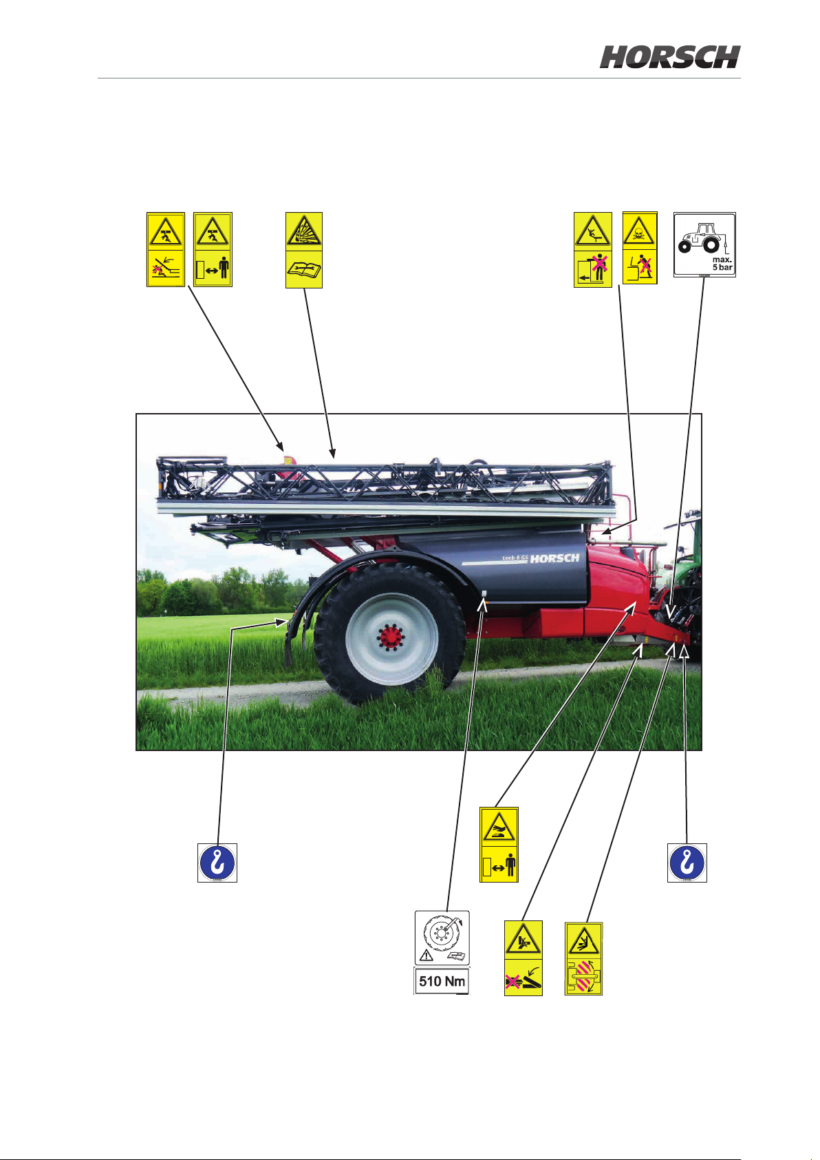
1.19 Position of safety
29
stickers
30
i
 Loading...