

horsch FOCUS ST, FOCUS TD Operating Instructions Manual
READ CAREFULLY PRIOR TO STARTING UP!
KEEP OPERATING INSTRUCTIONS IN A SAFE PLACE!
ART.:
ISSUE:
OPERATING INSTRUCTIONS
FOCUS TD / ST
80700201
02/2015

EC Declaration of Conformity
exchangeable equipment
(RL 2006/42/EC)
The manufacturer HORSCH Maschinen GmbH
Sitzenhof 1
D-92421 Schwandorf
hereby declares, that the product,
Designation of machine: Drill unit
Machine type: from serial no. 24341250 Focus 4 TD M14
24361250 Focus 6 TD M14
24361250 Focus 7 TD M14
24411250 Focus 6 TD 3-P
24371250 Focus 8.75 ST
24391250 Focus 8.90 ST
24401250 Focus 12.75 ST
this declaration refers to, conforms with all relevant fundamental health and safety requirements
of the EC directive 2006/42/EC.
For proper implementation of the heath and safety requirements mentioned in the EC-directive,
the following standards and technical specications have been used:
- EN 894-4 : 09-2010
- EN 1853 : 02-2010
- EN ISO 4254-1 : 05-2011
- EN ISO 4413 : 04-2011
- EN ISO 4414 : 04-2011
- EN 14018 : 02-2010
Schwandorf, 27.09.2014 Documentation Representative:
Place and date Manfred Köbler
____________________ ____________________
M. Horsch P. Horsch
(CEO) (Development and Engineering)

Acknowledgement of receipt
No right to claim warranty if this acknowledgement of receipt has not been returned!
* Mandatory eld
To
Dealer
Cust. No.: .................................................
Company ..................................................*
Street: ..... ................................................. *
ZIP-Code: ................................................*
Place: .......................................................*
Country: ................................................... *
Phone: .....................................................
Fax: ..........................................................
E-Mail: ......................................................
New machine sold to nal customer - Initial use*
Customer's machine - Relocation*
Demonstration machine - Initial use*
Demonstration machine - Relocation*
Demonstration machine sold to nal cus-
tomer - Use*
Machine type: ..........................................*
Serial number: ..........................................*
Service engineer
Name: ...................................................... *
First name: ...............................................*
I hereby conrm the receipt of the operating instructions and spare parts list for the machine specied above.
I have been instructed by an authorized dealer or a Service Engineer from HORSCH in the operation and functions as well as the safety related requirements of the machine.
I am aware, that the right to claim warranty will only be eective, if this form is returned to the
responsible dealer or handed over to the Service Engineer, properly completed immediately after
initial instruction.
........................................................................*
Signature of buyer
........................................................................*
Place, date of initial instruction
Customer I:
Name/company: ......................................*
Name of contact: .....................................*
First name of contact: .............................. *
Road: ....................................................... *
ZIP-Code: ................................................*
Place: .......................................................*
Country: ................................................... *
Phone ......................................................*
Fax: ..........................................................
E-Mail: ......................................................*
Customer II:
Name/company: ......................................*
Name of contact: .....................................*
First name of contact: .............................. *
Road: ....................................................... *
ZIP-Code: ................................................*
Place: .......................................................*
Country: ................................................... *
Phone ......................................................*
Fax: ..........................................................
E-Mail: ......................................................*
"


- Translation of the Original Operating Instructions -
Machine Identication
The corresponding data is to be entered into the list below upon
receiving the machine:
Serial number: ..................................................
Machine type: ...................................................
Year of construction: ........................................
Initial installation: ..............................................
Fittings: .............................................................
..........................................................................
..........................................................................
..........................................................................
Publication date of Operation Manual: 02/2015
Latest change: 04/2018
Address of Retailer: Name: ......................................................................
Road: ......................................................................
Town/City: ......................................................................
Tel.: ......................................................................
Customer No.:
Retailer: ......................................................................
Address of HORSCH: HORSCH Maschinen GmbH
92421 Schwandorf, Sitzenhof 1
92401 Schwandorf, Postbox 1038
Tel.: +49 (0) 9431 / 7143-0
Fax: +49 (0) 9431 / 7143-9200
E-mail: info@horsch.com
Customer No.:
HORSCH: ......................................................................
80700201 Focus TD/ST en

Table of contents
Introduction ...................................................4
Foreword ........................................................4
Notes on representation .................................4
Service............................................................5
Warranty claim processing .............................5
Consequential damage...................................5
Safety and responsibility .............................6
Intended use ...................................................6
Qualication of personnel ...............................7
Endangered children ......................................7
Personal protective outt ................................8
Safety in operation..........................................9
Fertiliser and dressed seed ..........................12
Environmental protection ..............................12
Retrots ........................................................12
Care and maintenance .................................13
Danger zone .................................................14
Safety stickers ..............................................15
Technical data...............................................17
Type plate .....................................................22
Calculating the ballasting..............................23
Design..........................................................25
Overview.......................................................25
Overview.......................................................26
Hydraulic system ..........................................27
Lighting .........................................................31
Notes on operation on the machine..............31
Tines .............................................................35
Coulter ..........................................................36
Levelling discs ..............................................37
Packer ..........................................................38
Coulter .........................................................38
Overview.......................................................38
Row spacing ..............................................41
Hose installation ........................................42
Commissioning ...........................................43
Delivery.........................................................43
Transport ......................................................43
Installation ....................................................43
Operation .....................................................44
Commissioning / Tractor change ..................44
Adapting the hose connection ...................44
Adapting the drawbar .................................45
Hitching up and transport position ................45
Hitching up .................................................45
Transport position ......................................45
Parking .........................................................46
Unfolding ......................................................46
Folding in ......................................................47
Access steps ..............................................47
Depth setting ................................................48
Depth of fertiliser placement ......................48
Depth of the levelling discs ........................48
Setting the drilling depth ...............................49
Hydraulic cylinders .....................................49
Coulter pressure ........................................49
Correlation .................................................49
Setting the depth ........................................49
Adjusting the lowering speed .....................50
Pneumatic system ........................................50
Fan ...............................................................50
Retightening the fan ange...........................51
Hopper .......................................................52
Distributor ..................................................53
Air ow .......................................................54
Empirical values .........................................54
Use in the eld ..............................................54
Checks..........................................................55
Optional equipment ....................................56
Brake system ................................................56
Pneumatic brake ........................................56
Hydraulic brake ..........................................57
Parking brake .............................................58
2

Optional equipment ....................................59
Crossbar .......................................................59
Settings on 3-point machines ....................59
Pre-emergence marker.................................60
LED working lights ........................................60
Border discs..................................................61
Maestro preparation kit .................................61
Disc harrow eld ...........................................62
Installing the disc harrow eld ....................62
Bout marker ..................................................64
Metering unit ...............................................65
Rotors ..........................................................65
Rotor change ................................................66
Rotor change with full hopper .......................66
Adjusting the sealing lip ................................67
Roller for ne seeds......................................67
Rape brushes ...............................................69
Coarse seeds ...............................................69
Metering unit with Venturi-type injector.........70
Servicing the metering unit ...........................71
Service and maintenance ..........................72
Cleaning .......................................................72
Maintenance intervals...................................72
Storage .........................................................73
Lubricating the machine ...............................73
Maintenance schedule..................................74
Lubrication points - Focus TD .......................76
Lubrication points Focus ST / TD 3-point .....77
Waste disposal ...........................................78
Tightening torques ........................................79
Index ............................................................81
3

Introduction
Foreword
Before operating the machine, read and strictly
comply with the operating instructions. In doing
so, you will avoid accidents, reduce repair costs
and downtime and increase the reliability and
service life of your machine. Pay attention to
the safety notices!
HORSCH will not assume liability for any damage or malfunctions resulting from failure to
comply with the operating instructions.
These operating instructions will assist you in
getting to know your machine and in using it correctly for its intended purposes.
The operating instructions must be read and
strictly adhered to by all persons working on or
with the machine e.g.:
• Operation (including preparation, fault recti-
cation during work, servicing)
• Maintenance (maintenance and inspection)
• Transport
Together with the operating instructions, you
also receive an acknowledgement of receipt.
The trained personnel of our service and sales
partners will train and instruct you in the operation and maintenance of your machine. You or
the service engineer should pass the acknowledgement of receipt on to the sales partner.
This conrms your formal acceptance receipt
of the machine.
The warranty period starts with the date of
delivery.
We reserve the right to alter illustrations as well
as technical data and weights contained in these
operating instructions for the purpose of improving the machine.
The illustrations in these operating instructions
show dierent versions of the implement and
dierent equipment variants.
Notes on representation
Warning notes
These operating instructions dierentiate between three dierent types of warning notes.
The following signal words with warning symbols are used:
DANGER
Highlights a danger that will lead to death or
severe injury, if it is not avoided.
WARNING
Highlights a danger that can lead to death or
severe injury, if it is not avoided.
CAUTION
Highlights a danger that can lead to injury, if it
is not avoided.
Please read the warning notes given in these
operating instructions!
Instructions
In the operating instructions all instructions for
actions are identied by arrow heads
¾ ...
¾ ...
If compliance with a certain sequence is required, the steps of actions are successively
numbered.
1. ...
2. ...
3. ...
...
Identies important notes.
The designations “right”, “left”, “front” and “rear”
apply as seen in travel direction.
4

Service
The company HORSCH would be pleased, if
your machine and our services would meet your
expectations.
If you encounter any problems, please feel free
to contact your sales partner.
The service sta of our sales partners and the
service employees at Horsch will always be
available for assistance.
In order to be able to solve technical problems
as quickly as possible, we ask you kindly to
support us.
Please help the service personnel by providing
the following information to avoid unnecessary
queries.
• Customer number
• Name of customer representative
• Name and address
• Machine model and serial number
• Purchasing date and operating hours or area
performance
• Type of problem
Warranty claim
processing
Warranty claim forms must be submitted to
HORSCH through your local HORSCH sales
partner.
Consequential damage
The machine has been manufactured by
HORSCH with greatest care. However, despite
the intended use deviations in placement quantity up to total failure may be caused by e.g.:
• damage caused by external inuences
• wear of wear items
• missing or damaged cultivation tools
• incorrect travel speeds
• incorrect setting of the unit (incorrect connec-
tion, non-observance of setting tables).
• failure to comply with the operating instructions.
• neglect and improper care and maintenance
Therefore, it is crucial to always check your
machine before and during operation for correct
operation and adequate application accuracy.
Compensation claims for damages which have
not been caused by the machine, are excluded.
This also includes that any liability for consequential damages caused by travel and operating faults, is excluded.
5

Safety and
responsibility
The following warnings and safety instructions apply to all sections in these operating instructions.
The machine has been built in accordance with
latest technical standards and generally accepted safety regulations. However, risks for
life and limb of the operator or third parties and
impairment of the machine or other material assets can occur during use.
Please read and comply with the following safety
notes, before you start to use the machine!
Intended use
The machine is intended for normal use in soil
cultivation in accordance with agricultural practice. Any other use or use beyond the limitations
of intended use, like e.g. as transport means,
is considered unintended use and can lead to
persons being severely or fatally injured.
HORSCH will not assume liability whatsoever for
damage resulting from unintended use. The risk
will be borne solely by the user.
The respective accident prevention regulations
of the agricultural liability associations and other
generally recognised safety-related, occupa-
tional medical and road trac regulations are
to be adhered to.
The machine must only be operated in a technically perfect condition and in a safety and danger
conscious manner!
Faults, particularly those which impair safety,
must be remedied immediately.
The machine must only be operated, serviced
and repaired by persons who are familiar with
it and have been made aware of the dangers
involved. See “Qualication of personnel”.
Spare parts
Genuine spare parts and accessories from
HORSCH have been specially designed for this
machine.
Spare parts and accessories which are not delivered by us, have not been tested or approved
by us.
Installation or use of non-original HORSCH
products may have a detrimental effect on
specic design features of the machine and
impair the safety of machine operators and the
machine itself.
HORSCH will not assume liability whatsoever for
damage resulting from the use of non-original
parts and accessories.
If the component to be replaced is marked with
a safety sticker, these stickers must also be
ordered and attached to the spare part.
Operating Instructions
Intended use also includes the strict compliance
with the operating instructions and adherence to
the operating, maintenance and repair instruc-
tions specied by the manufacturer.
The operating instructions are a component part
of the machine.
The machine is solely intended for use as described in the operating instructions. Failing to
comply with the operating instructions can result
in severe or even fatal physical injuries.
¾ Read and follow the corresponding sections in
the operating instructions before starting work.
¾ Store the operating instructions and keep for
future use.
¾ Pass the operating instructions on to a later
user. When selling on into countries with dierent languages, pass on in the corresponding
ocial language.
6

Qualication of personnel
Unintended use of the machine can lead to severe or even fatal physical injuries. In order to
prevent accidents, each person involved in work
with the machine must meet the following general
minimum requirements:
¾ The person must be physically able to keep
the machine under control.
¾ The person is able to perform work with the
machine safely within the scope of these operating instructions.
¾ The person is acquainted with the function of
the machine within the scope of its work and
is able to assess and avoid any work related
dangers. The person is able to recognize and
avoid work related dangers.
¾ The person has understood the operating
instructions and is able to implement the information given in the operating instructions
accordingly.
¾ The person is fully familiar with the safe opera-
tion of the vehicle.
¾ The person knows all applicable road trac
regulations and is in possession of a valid
driving permit for road travels.
¾ A person being instructed must only work with
or on the machine under the supervision of
an experienced person.
The owner of the machine must
¾ regulate the area of responsibility, compe-
tence and monitoring of personnel.
¾ if necessary train and instruct the personnel.
¾ make the operating instructions accessible for
the machine operator.
¾ ensure that the operator has read and under-
stood the operating instructions.
Groups of operators
Persons who work with the machine must have
been trained for the dierent activities involved.
Instructed operators
These persons must have been trained for their
duties by the owner or other qualied experts.
This refers to the following activities:
• Road transportation
• Application and set-up work
• Operation
• Maintenance
• Troubleshooting and repair
Operators trained by HORSCH
Furthermore, for certain activities the corresponding personnel must have been trained by
service personnel from HORSCH. This refers to
the following activities:
• Loading and transport
• Commissioning
• Troubleshooting and repair
• Waste disposal
Certain work concerning maintenance and repair
must only be carried out by an expert workshop.
Such work is identied with the additional comment “Workshop work”.
Endangered children
Children are not able to assess dangers and may
behave unpredictably. Children are therefore
especially endangered:
¾ Keep children away from the machine.
¾ Especially when starting to drive and before
triggering machine movements you must
make sure that the danger zone is free of
children.
¾ Shut down the tractor before leaving it.
Children can trigger dangerous machine
movements. An insuciently secured machine parked without being attended poses
a danger for playing children!
7

Personal protective outt
Missing or incomplete protective outt increases
the risk of health damage. Personal protective
outt includes, e.g.:
¾ Tight tting clothes / protective clothing, pos-
sibly a hair net
¾ Safety shoes, protective gloves
¾ Safety goggles to protect the eyes against
dust or spray, when working with fertiliser or
liquid fertiliser (follow the instructions of the
fertiliser manufacturer)
¾ Respiratory masks and protective gloves
when handling dressing or dressed seed
(follow the instructions of the pickling agent
manufacturers)
¾ Determine the personal protective outt for
the corresponding work place.
¾ Provide effective protective equipment in
proper condition.
¾ Never wear rings, bracelets or other jewellery
Safety in trafc
DANGER
No passengers are allowed to ride on the
machine!
¾ Pay attention to the permissible transport
widths and heights. Pay attention to the transport height when passing under bridges and
low hanging overhead power lines.
¾ Do not exceed the permissible axle loads, tyre
carrying capacities and total weights, in order
to ensure sucient steering and braking capabilities. The front axle must be loaded with at
least 20 % of the tractor weight.
For road transport the machine must be set to
transport position. The machine must have been
folded up and secured, see chapter “Folding” and
“Hitching up and transport position”.
¾ Clean soil from the folding areas before fold-
ing up. Otherwise there could be damage to
the mechanics.
¾ If available: Secure the hydraulic cylinders on
undercarriage and drawbar in transport position against uncontrolled movements using
aluminium clips, see chapter “Hitching up and
transport position”.
¾ Assemble lighting, warning and protective
equipment and check the function.
¾ Before driving on roads clean the entire ma-
chine from picked up dirt.
Handling is aected by the connected equipment.
¾ Pay particular attention to the wide overhang
and the centrifugal mass of the working implement when cornering.
Lifted machine (Three-point hydraulics):
¾ Consider the limited stability and steerability
of the tractor.
For transport on public roads only drive
with empty seed hopper.
For transport on public roads pay attention to the permissible top speed mentioned in the operating licence!
The specications in the type approval
documenht or in the technical data are decisive for the design dependent top speed.
Always match the travel speed to the
road conditions to avoid accidents and
damage to the undercarriage.
Consider your personal abilities, carriage
way, trac, sight and weather conditions.
8

Safety in operation
Commissioning
The operational safety of the machine cannot
be guaranteed without an orderly performed
commissioning. This can lead to accidents with
severe or even fatal physical injuries.
¾ The machine must only be put into operation
after receiving instructions by employees of the
authorized dealer or a HORSCH employee.
¾ The machine registration form must be com-
pleted and returned to HORSCH.
All protective features and safety equipment,
such as detachable protective devices (wedges,
etc.), must be correctly in place and reliably functioning before the machine is put into operation.
¾ Check nuts and bolts, especially the ones on
wheels and cultivation tools regularly for tight
t and retighten if necessary.
¾ Check the tyre pressure at regular intervals,
see maintenance overview.
Damage to the machine
Damage to the machine can impair the operational safety of the machine and cause accidents. This can lead to severe or even fatal
physical injuries.
The following machine parts are particularly
important for safety:
¾ Hydraulic system
¾ Brakes (as far as available)
¾ Connecting features
¾ Protective features
¾ Lighting
If in doubt about the safety relevant status of the
machine, e.g. in case of leaking out operating
uids, visible damage or unexpected changes
in travel behaviour:
¾ Immediately shut down and secure the machine.
¾ If possible locate and rectify the faults by fol-
lowing these operating instructions.
¾ Rectify possible causes for damage (e.g. re-
move coarse dirt and tighten loose screws).
¾ Have damage, that could aect safety and
that cannot be rectied by yourself, rectied
by a qualied expert workshop.
Hitching and unhitching
Faulty hitching up of the machine to the pulling
tool of the tractor causes dangers, whic´h could
result in severe accidents.
¾ Strictly comply with all operating instructions:
• These operating instructions (chapter “Hitch-
ing up and transport position” and “Parking”)
• Operating instructions of the tractor
¾ Take special care when reversing the tractor.
Never stand between tractor and machine.
¾ Only park the machine on a rm and level
surface. Before unhitching the machine, lower
it to the ground.
¾ Secure the machine against rolling away.
9

Hydraulic system
The hydraulic system is under high pressure.
Hydraulic oil escaping under pressure can penetrate the skin and cause serious injuries. In the
event of injury, consult a doctor immediately.
The machine's hydraulic system has several
functions, which can cause injury to persons or
damage to the machine, if operated incorrectly.
¾ Do not connect hydraulic hoses to the tractor,
before both hydraulic systems on machine
and tractor are de-pressurised.
¾ The hydraulic system is under high pressure.
Check all lines, hoses and screwed connections regularly for leaks and any visible
external damage!
¾ Use only appropriate means when searching
for leaks. Repair any damage immediately!
Oil sprays can cause injuries and re!
¾ Power sockets and connectors on the hydrau-
lic connections should be marked in order to
exclude operating errors.
¾ In the case of injury, contact a doctor imme-
diately!
¾ Secure and lock the control unit on the tractor,
if not in use!
¾ Replace hydraulic hoses at the latest after six
years, see “Maintenance overview”.
Pressure accumulator
The hydraulic system may be equipped with a
pressure accumulators.
¾ Do not open or work (welding, drilling) on pres-
sure accumulators. Even when empty, the accumulator is still preloaded by gas pressure.
The hydraulic system must be depressurized
before maintenance!
Brake system
Depending on the equipment, the machines can
be equipped with a pneumatically or hydraulically operated service brake system.
For road travel the brake system must always
be connected and fully functional.
¾ After hitching the machine and before trans-
portation you should always check the function and condition of the brake system.
¾ Check the setting on the brake pressure
regulator.
¾ Always release the parking brake before start-
ing to drive.
¾ Always secure the machine against rolling
away and apply the parking brake before
unhitching.
Adjustments and repair work on the brake system must only be carried out in a professional
workshop or by an operator, who has been
specially trained by HORSCH.
Overhead power lines
When unfolding or folding the wings, the machine may reach the height of overhead power
lines. Possible voltage ashover to the machine
causing fatal electric shock or re.
¾ Keep a safe distance to electric high voltage
power lines with the folded up machine or when
unfolding or folding the machine.
¾ Do not unfold or fold the wings in the vicinity
of pylons and power lines.
¾ Never leave or access the machine under
overhead power lines to avoid possible risks
of electric shock or voltage ashover.
10

What to do in case of voltage ashover
Voltage ashover generates high electric voltages on the outside of the machine. This results
in extreme voltage dierences at the ground
around the machine. Wide strides, laying on the
ground or supporting yourself with your hands
on the ground can cause life-threatening electric
currents (pace voltage).
¾ Do not leave the cabin.
¾ Do not touch any metal objects.
¾ Do not create a conductive connection to
ground.
¾ Warn persons: DO NOT come near the ma-
chine. Electric voltages at the ground can
cause severe electric shock.
¾ Wait for professional rescuers. The overhead
power line needs to be switched o.
If persons need to leave the cabin despite the
voltage ashover, e.g. in case of a potential lifethreatening risk of re:
¾ Jump away from the machine. Ensure a safe
stand when jumping. Do not touch the outside
of the machine.
¾ Move away from the machine with short step-
ping strides.
Technical limiting values
If the technical limiting values of the machine
are not complied with, the machine may get
damaged. This can lead to accidents with severe
or even fatal physical injuries.
The following technical limiting values are of
particular importance for safety:
• permissible total weight
• maximum axle loads
• maximum drawbar load
• top speed
See chapter “Technical data”, type plate and
type approval.
¾ Also pay attention to the max. permitted loads
for the tractor.
Use in the eld
DANGER
No passengers are allowed to ride on the
machine!
¾ Check the area around the machine (for chil-
dren!) before setting o and starting operation
of the machine. Ensure sucient visibility.
¾ Ensure sucient stability of the machine in
case of longitudinal or transverse inclination
when working in uneven terrain. Pay attention
to the limiting values for the tractor!
¾ Do not remove any of the mandatory and
supplied protective devices.
¾ Stay clear of the operating range of hydrauli-
cally operated parts.
¾ Do not drive backwards with the machine
lowered. The components have only been
designed for forward travel in the eld and
may be damaged when reversing.
Changing equipment / wear items
¾ Secure the machine against unintended roll-
ing away!
¾ Secure raised frame parts you have to work
under with suitable supports!
¾ Caution! Danger of injury caused by projecting
parts (e.g. coulters)!
Do not use packer tyres or other rotating parts
to climb on the machine. These could rotate and
you could be seriously injured by falling down.
11

Fertiliser and dressed
seed
Inappropriate handling of fertiliser and dressed
seed can cause poisoning and death.
¾ Follow the information given in the safety
data sheet of the manufacturer. If necessary
ask the dealer for the corresponding safety
data sheet.
¾ Determine and provide the personal protective
outt as specied by the manufacturer.
Environmental protection
Operating materials such as hydraulic oil, lubricants, etc. can damage the environment and the
health of persons.
¾ Do not allow operating materials to drain out
into the environment.
¾ Take up drained out operating materials with
absorbent material or sand, ll it into a leak
tight container and dispose of in accordance
with statutory regulations.
Retrots
Structural changes and extensions can adverse-
ly aect the functionality and the operational
safety of the machine. This can lead to severe
or even fatal physical injuries.
¾ Do not make any structual changes or ex-
tensions which have not been approved by
HORSCH.
¾ Structural changes and extensions must only
be made in an authorized workshop or by an
operator who has been trained by HORSCH.
¾ Comply with country specic instructions fr
weights, weight distribution and dimensions.
For equipment inuencing the weight or weight
distribution one must check and comply with the
regulations concerning towing facilities, support
and axle loads.
For machines without brakes a brake system
may need to be retrotted, if the permissible
weight limits are exceeded.
In case of changes concerning data mentioned
on the type plate, a new type plate with updated
data must be attached.
In case of changes which concern the data in
the type approval, this type approval needs to
be renewed.
12

Care and maintenance
Inappropriate care and maintenance puts the
operational safety of the machine at risk. This
can lead to accidents with severe or even fatal
physical injuries.
¾ Conform with prescribed schedules for repeti-
tive tests or inspections.
¾ Service the machine according to the
maintenance plan, see chapter “Care and
maintenance”.
¾ Only perform the work described in these
operating instructions.
¾ Before starting maintenance and service work
park the machine on level and rm ground and
secure it against rolling away.
¾ De-pressurise the hydraulic system and lower
or support the implement.
¾ Prior to working on the electrical system,
disconnect it from the electric power supply.
¾ Before cleaning the machine with high pres-
sure cleaning equipment cover all openings,
which should stay clear of water, steam or
cleaning agents for reasons of safety or
operation. Do not aim the water jet directly
on electric or electronic components and
bearings.
¾ When cleaning with high pressure or steam
cleaning equipment keep a distance of at least
50 cm to machine components.
¾ After cleaning, check all hydraulic lines for
leaks and loose connections.
¾ Check for chang and signs of other damage.
Remedy any faults immediately!
¾ Screw connections loosened for the purpose
of maintenance and service work must be
retighten after work is completed.
¾ All other maintenance and repair tasks,
which are not described in the operating
instructions, must only be carried out by
an authorized professional workshop or
by an operator who has been trained by
HORSCH for this purpose.
Do not clean new machines with a steam jet
of a high pressure cleaner. The paint takes
approx. 3 months to cure and could thus be
damaged if this time has not yet expired.
13

Danger zone
The area marked red indicates the danger zone
of the machine:
The danger zone around the machine poses the
following endangerments:
¾ Accidental operation of the hydraulic system
can trigger dangerous movements of the
machine.
¾ Defective or not correctly fastened electric
lines can cause electric shocks.
¾ With the drive still running, machine parts may
rotate or swing out.
¾ Hydraulically raised machine parts can lower
slowly and unnoticed.
Failing to pay attention to the danger zone can
result in severe or even fatal physical injuries.
¾ Do not stand under lifted loads. Lower such
loads to the ground rst.
¾ Instruct persons to leave the danger zone
around the machine and tractor.
¾ Before working in the danger zone of the ma-
chine or between machine and tractor: Shut
down the tractor!
This also applies for short-term inspection work.
Many accidents happen because of carelessness and running machines!
¾ Pay attention to the information in all operat-
ing instructions.
14

Safety stickers
Safety stickers on the machine warn of endangerments at dangerous points and are an
important part of the safety equipment of the
machine. Missing safety stickers increase the
risk of severe or even fatal physical injuries.
¾ Clean soiled safety stickers.
¾ Damaged or illegible safety stickers must be
replaced immediately.
¾ Provide spare parts with the specied safety
stickers.
No passengers are allowed to ride
on the machine!
00380054
Before starting operation of the
machine you should read and follow
the operating instructions!
00380055
Watch out for uids spraying out
under high pressure, follow the
operating instructions!
00380133
Never reach into areas where there
is a risk of crushing, as long as parts
could still be moving!
00380134
Stay clear of swinging area of retractable and extendible machine
parts!
00380135
Shut the engine down and pull o
the key before starting maintenance
and repair work.
00380294
Do not climb on rotatable parts.
Use mounting steps provided for
this purpose.
00380299
The pressure accumulator is
charged with gas or oil pressure.
Dismantle and repair only in strict
compliance with the instructions in
the technical manual.
00380252
15
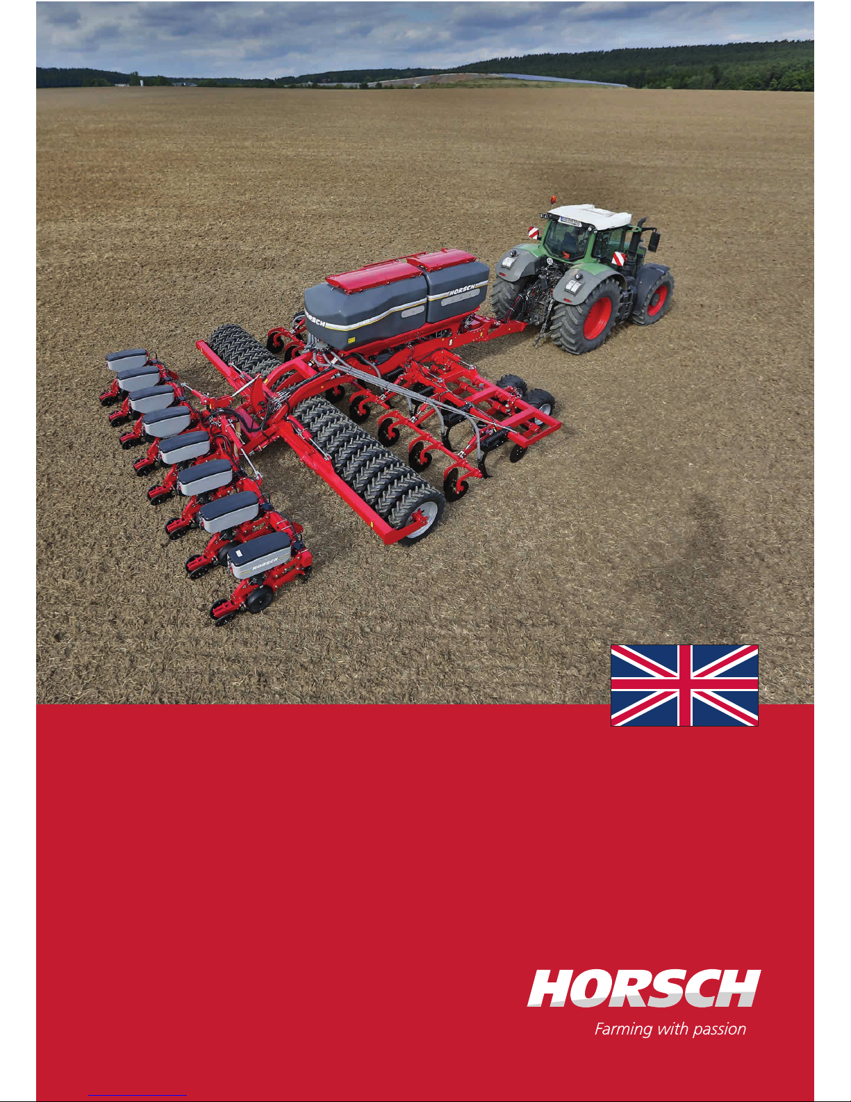
Position of safety stickers
(depending on equipment)
00380134
00380135
00380896
00380054
00380055
00380133
00380294
00380299
00380894
00380299
00380134
00380135
00380252
In order to prevent eye injuries, do not
look directly at the beam area when
the radar sensor is switched on!
00380894
It is only permitted to remain in the
danger zone when the lifting cylin
-
der safety device is applied.
00380896
16

Focus 4 TD 6 TD 7 TD
Length (m) 9.77 10.40 10.55
Working width (m) 4.00 6.00 7.20
Transport width (m) 3.00 3.00 3.00
Transport height (m) 3.35 3.55 4.00
Weight (kg) 8,430 10,520 11,920
Capacity of twin hopper (l) 5,000 (2,000 ltr. : 3,000 ltr. / 40 : 60)
Dimensions of ller opening (m) Front 0.66 x 1.22 / Rear 0.66 x 1.68
Filling height twin hopper (m) 2.95
Tyre size support wheels on side 15.0/55-17
Tyre packer size 210/95-24 AS
Tyre packer Ø (cm) 100
Number of tines 14 20 24
Tine spacing in row (cm) 57.2 60 60
Groove spacing (cm) 28.6 30 30
Frame height (cm) 75
Number of coulters 14/28 20/40 24/48
Row spacing (cm) 28.6/14.3 30/15 30/15
Coulter pressure of seed coulter (kg) 5 - 120
Seed coulters / press rollers (cm) 34
Working speed (km/h) 6 - 10
Required power (kW/PS) 150-220/200-300 220-295/300-400 260-370/350-500
Control units, double-acting 2
Pressureless return ow (max. 5 bar) 1
Oil quantity hydr. fan (ltr./min) 35-45
max. system pressure hydraulics (bar) 210
Implement hitching tractor link arm Cat. III - III / IV - IV
Implement hitching adjustable drawbar Bolt Ø 50 - 70 mm
Attachment of ball head K 80
E-Manager Series
Lighting Series
Design related top speed 25 km/h / Data in type approval
Technical data
17

Focus 6 TD 3-point 7 TD 3-point
Length (m) 10.60 10.60
Working width (m) 6.00 7.20
Transport width (m) 3.00 3.00
Transport height (m) 3.55 4.00
Weight (kg) 10,820 11,470
Capacity of twin hopper (l) 5,000 (2,000 ltr. : 3,000 ltr. / 40 : 60)
Dimensions of ller opening (m) Front 0.66 x 1.22 / Rear 0.66 x 1.68
Filling height twin hopper (m) 2.95
Tyre size support wheels on side 15.0/55-17
Tyre packer size 210/95-24 AS
Tyre packer Ø (cm) 100
Number of tines 20 24
Tine spacing in row (cm) 60 30
Groove spacing (cm) 30
Frame height (cm) 75
Number of coulters 20/40 24/48
Row spacing (cm) 30 / 15
Coulter pressure of seed coulter (kg) 5 - 120
Seed coulters / press rollers Ø (cm) 34 / 32
Working speed (km/h) 6 - 10
Required power (kW/PS) 220-295/300-400 260-370/350-500
Control units, double-acting 2 (+1 each for Maestro preparation kit, hydraulic
depth setting disc harrow eld)
Pressureless return ow (max. 5 bar) 1
Oil quantity hydr. fan (ltr./min) 35-45
max. system pressure hydraulics (bar) 210
Implement hitching tractor link arm Cat. III - III / IV - IV
Implement hitching adjustable drawbar Bolt Ø 50 - 70 mm
Attachment of ball head K 80
3-point implement hitching coulter bar Cat. III/III
E-Manager Series
Lighting Series
Design related top speed 25 km/h / Data in type approval
18

Focus 8.75 ST 8.90 ST 12.75 ST
Length (m) 10.60 10.60 10.60
Working width - TurboDisc drill bar (m) 5.625 7.20 8.625
Working width - Maestro RC (m) 6.00 7.20 9.00
Transport width (m) 3.37 3.20 3.75
Transport height (m) 3.45 4.00 4.75
Weight incl. coulter bar (kg) 9,430 11,470
Capacity of twin hopper (l) 5,000 (2,000 ltr. : 3,000 ltr. / 40 : 60)
Dimensions of ller opening (m) Front 0.66 x 1.22 / Rear 0.66 x 1.68
Filling height twin hopper (m) 2.95
Tyre size support wheels on side 15.0/55-17
Tyre packer size 210/95-24 AS
Tyre packer Ø (cm) 100
Number of tines 15 24 23
Groove spacing (cm) 37.50 30 37.50
Number of tines - reduced 8 8 12
Groove spacing tines reduced (cm) 75 90 75
Cutting discs qty./Ø (cm) 8 / 50 8 / 50 12 / 50
Frame height (cm) 85
Number of coulters 15 / 30 24 / 48 23 / 46
Row spacing (cm) 37.50 / 18.75 30 / 15 37.50 / 18.75
Coulter pressure of seed coulter (kg) 5 - 120
Seed coulters / press rollers Ø (cm) 34 / 32 34 / 32 34 / 32
Working speed (km/h) 6 - 10
Required power (kW/PS) 165-270/225-370 165-370/225-
500
250-370/340-500
Control units, double-acting 2 (+1 each for Maestro preparation kit/8.90 ST: hy-
draulic depth setting disc harrow eld)
Pressureless return ow (max. 5 bar) 1
Oil quantity hydr. fan (ltr./min) 35-45
max. system pressure hydraulics (bar) 210
Implement hitching tractor link arm Cat. III - III / IV - IV
Implement hitching adjustable drawbar Bolt Ø 50 - 70 mm
19
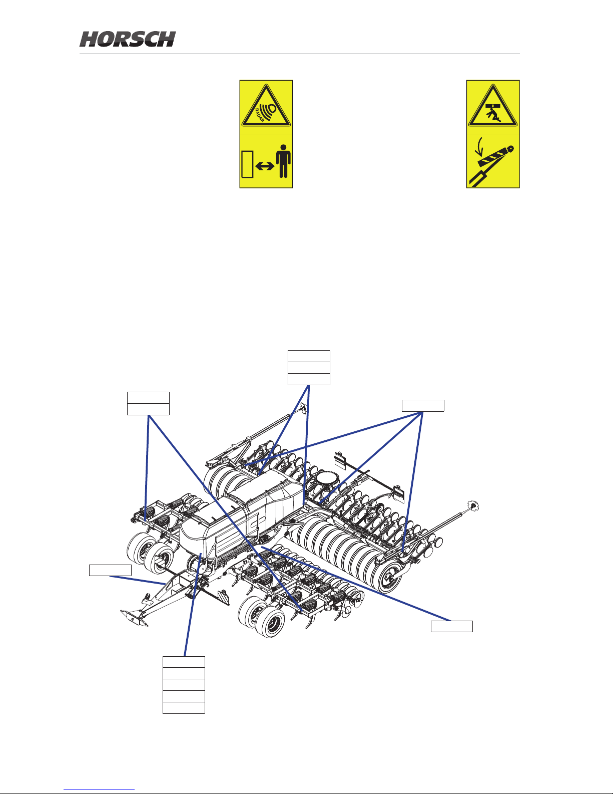
3000
9770
3350
Focus 4 TD
3550
3000
10400
Focus 6 TD
Focus 8.75 ST 8.90 ST 12.75 ST
Attachment of ball head K 80
3-point implement hitching coulter bar Cat. III/III
E-Manager Series
Lighting Series
Design related top speed 25 km/h / Data in type approval
NOTE:
• The right for deviations caused by the technical further development remains reserved.
• The weight of the hitched implement depends on the equipment; data with minimum equipment
• The permissible transport heights and transport width for transport on public roads may dier from country to country.
Comply with the national approval regulations.
20
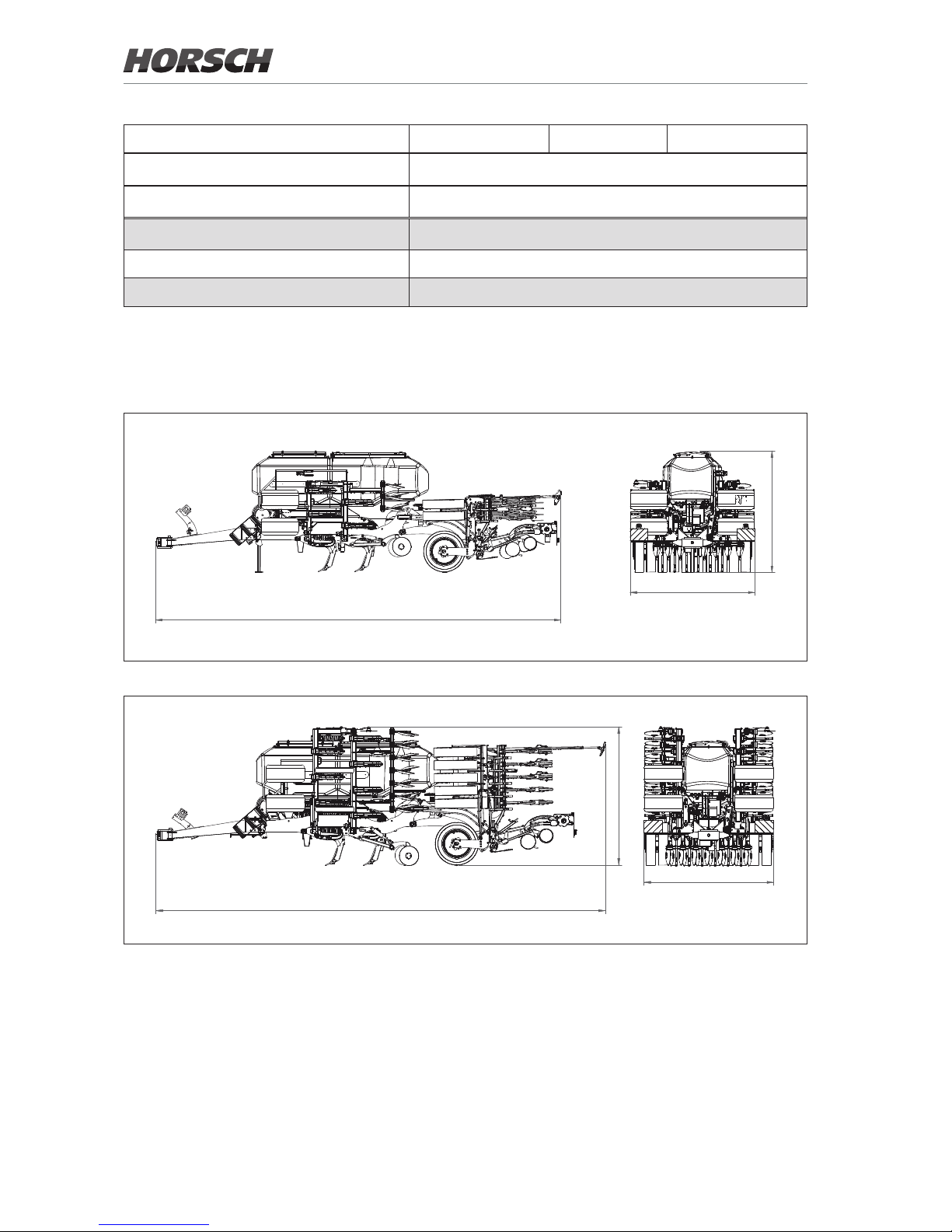
10550
3000
4000
Focus 7 TD
10600
3550
3000
Focus 6 TD 3-point
10540
3110
3300
Focus 8.75 ST
21
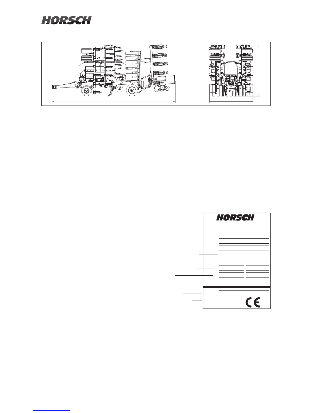
Type plate
The type plate with the CE-mark is located on
the frame of the machine.
Data on the type plate:
Serial number
Permissible total weight
Drawbar load (= DL)
Axle load
Machine type
Year of construction
!"#$ %&'()"#
*+,('-./'(01(&.
23 ,('-./'(0(4(
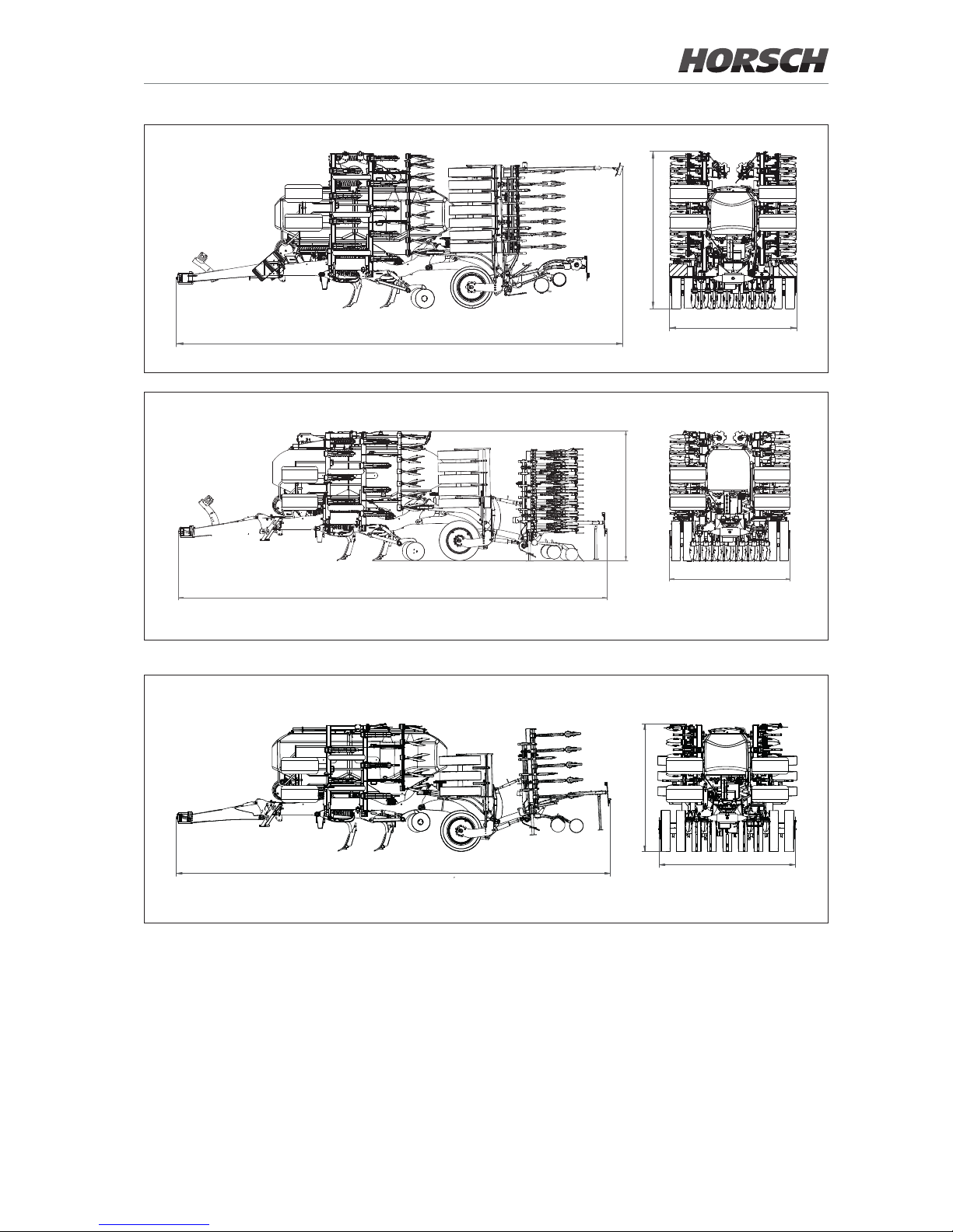
3750
10600
4750
Focus 12.75 ST
22
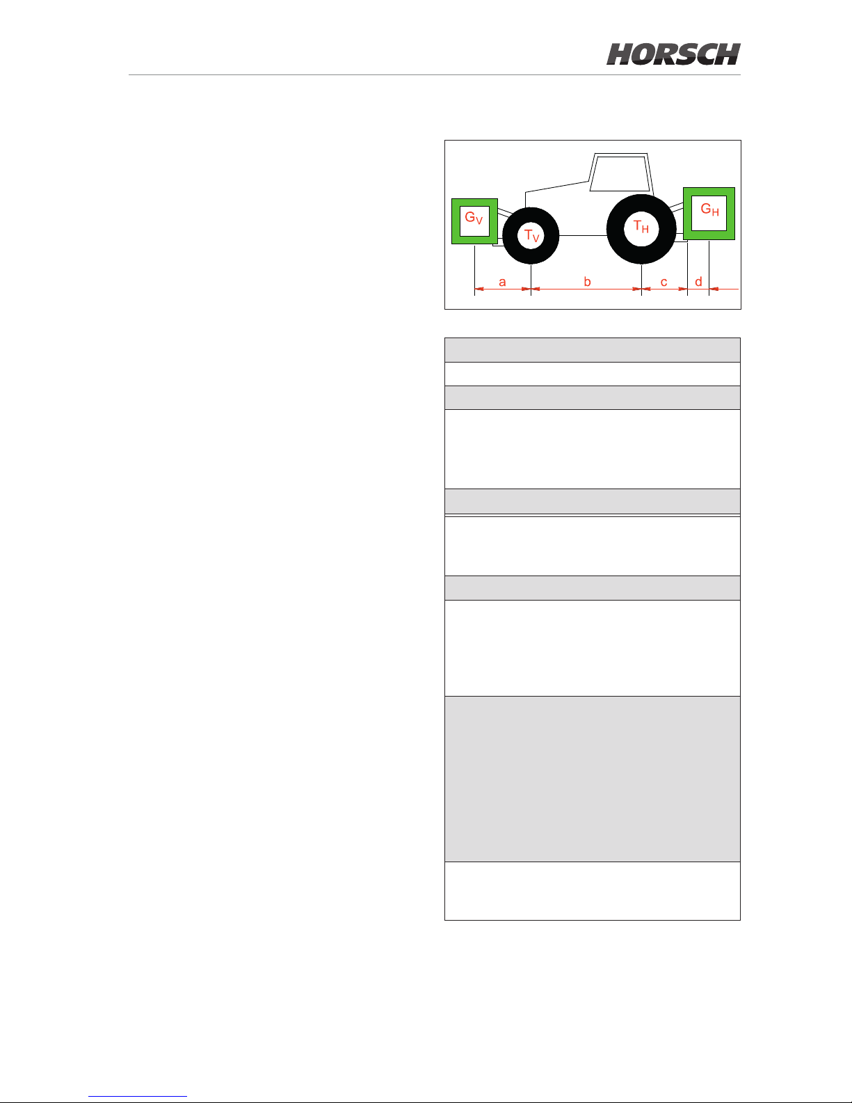
Calculating the ballasting
The permissible total weight, the permissible
axle loads and the load bearing capacity of the
tyres must not be exceeded when mounting or
hitching up implements.
The front axle of the tractor must always be
loaded with at least 20 % of the curb weight of
the tractor.
¾ Before transportation on public roads you
must make sure that the tractor is not overloaded and suitable for this implement.
¾ Weigh the implement separately. Since dif-
ferent equipment variants are possible, the
weight of the implement must be determined
by weighing.
Required data:
T
L
Curb weight of tractor
T
V
Front axle load of empty tractor
T
H
Rear axle load of empty tractor
G
H
• Total weight of rear implement
• In case of towed machines:
Maximum permissible drawbar load
for road transport.
G
V
Total weight of front implement
a
Distance from centre of gravity of front
implement (front ballast) to middle of
front axle
b
Tractor wheel base
c
• Distance from middle of rear axle to
middle of tractor link arm ball
• In case of towed machines:
Distance from middle of rear axle to
middle of hitch-up point.
d
• Distance from middle of tractor link
arm ball to centre of gravity of rear
mounted implement (rear ballast)
Concerning the centre of gravity
see chapter "technical data"; if necessary pay attention to the correct
choice of the centre of gravity.
• The following applies with towed
machines: d = 0
x
Information of tractor manufacturer for
minimum rear ballasting. If no information is available, enter 0.45.
All specied weight in (kg)
All specied dimensions in (m)
23
 Loading...