

Page 1
TRANSLATION OF THE ORIGINAL OPERATING INSTRUCTIONS
READ CAREFULLY PRIOR TO STARTING UP!
KEEP OPERATING INSTRUCTIONS IN A SAFE PLACE!
ART.:
ISSUE:
OPERATING INSTRUCTIONS
02
04
08/2018
8083
Express TD
Page 2

Page 3

- Translation of the Original Operating Instructions -
Machine Identication
The corresponding data is to be entered into the list below upon
receiving the machine:
Serial number: ..................................................
Machine type: ...................................................
Year of construction: ........................................
Initial installation: ..............................................
Fittings: .............................................................
..........................................................................
..........................................................................
..........................................................................
Publication date of Operation Manual:
Latest change:
Address of Retailer: Name: ......................................................................
Road: ......................................................................
Town/City: ......................................................................
Tel.: ......................................................................
Customer No.:
Retailer: ......................................................................
Address of HORSCH: HORSCH Maschinen GmbH
92421 Schwandorf, Sitzenhof 1
92401 Schwandorf, Postbox 1038
Tel.: +49 (0) 9431 / 7143-0
Fax: +49 (0) 9431 / 7143-9200
E-mail: [email protected]
Customer No.:
HORSCH: ......................................................................
Conrmation of receipt of machinery
Warranty claims become only eective when the rst use of the machine is reported to HORSCH
Maschinen GmbH within a week.
At www.horsch.com under SERVICE PARTNERBEREICH an interactive PDF form is available for down-
load for this purpose (not available in all languages).
By clicking on Send – depending on the email program installed – a mail draft with the completed
form is generated automatically. Alternatively, the form can be sent as email attachment to machine.
[email protected].
A dierent form of registration (postal mail, by fax, etc.) is not allowed for.
en
02
08/2018
Express TD
8083 04
Page 4

EG-Konformitätserklärung
Die
HORSCH Maschinen GmbH
Sitzenhof 1, D-92421 Schwandorf
erklärt hiermit in alleiniger Verantwortung als Hersteller, dass das nachfolgend genannte Produkt:
Typ:
den einschlägigen grundlegenden Sicherheits- und Gesundheitsanforderungen der Richtlinie
2006/42/EG entspricht.
Schwandorf, 24.10.2017 Klaus Winkler
Dokumentationsbevollmächtigter
_________________________ _________________________
Michael Horsch Philipp Horsch
Geschäftsführer Geschäftsführer
Sämaschine
Express 3 TD
Express 3,5 TD
Translation of EC Declaration of Conformity
(Directive 2006/42/EC)
The manufacturer HORSCH Maschinen GmbH
Sitzenhof 1
D-92421 Schwandorf
hereby declares that the product
Type: Express 3 TD
Express 3.5 TD
this declaration refers to, conforms with all relevant fundamental health and safety requirements
of the EC directive 2006/42/EC.
Schwandorf, 24/10/2017 Klaus Winkler
Documentation Representative
Michael Horsch Philipp Horsch
Managing director Managing director
Drill
Page 5

Page 6

Table of contents
Introduction ...................................................4
Foreword ........................................................4
Notes on representation .................................4
Service............................................................5
Warranty claim processing .............................5
Consequential damage...................................5
Safety and responsibility .............................6
Intended use ...................................................6
Qualication of personnel ...............................7
Children in danger ..........................................8
Personal protective outt ................................8
Safety in trac ................................................8
Safety in operation..........................................9
Fertiliser and dressed seed .......................... 11
Environmental protection ..............................12
Retrotting and conversions .........................12
Care and maintenance .................................13
Danger zone .................................................14
Safety stickers ..............................................15
Technical data .............................................17
Type plate .....................................................17
Requirements on the tractor .........................18
Calculating the ballasting..............................21
Design..........................................................23
Overview.......................................................23
Hydraulics .....................................................24
Identication of hydraulic hoses ...................24
Lighting .........................................................28
Instruction stickers ........................................29
Commissioning ...........................................31
Delivery.........................................................31
Transport ......................................................31
Installation ....................................................31
Operation .....................................................32
Connecting/Parking ......................................32
Connecting ...................................................32
Transport position .........................................33
Parking .........................................................34
Use in the eld ..............................................35
Working speed ...........................................36
Headland ...................................................36
Checks .......................................................36
After sowing ...............................................37
Settings .......................................................38
DiscSystem ...................................................38
Hydraulic adjustment (option) ....................38
Track loosening discs ................................39
Side plates .................................................39
FarmFlex Packer .......................................40
Pneumatic system ........................................41
Fan .............................................................41
Direct drive .................................................42
PTO-shaft drive (option) ............................43
Checks and maintenance ..........................44
Hopper .......................................................45
Metering unit ...............................................47
Rotors ...........................................................47
Roller change ...............................................48
Roller change with gate valve.......................48
Roller change at full hopper without
gate valve .....................................................49
Adjusting the sealing lip ................................49
Rotors for ne seeds ....................................50
Rape brushes ...............................................51
Coarse seeds ...............................................52
Maintenance of the metering unit .................53
Calibration ..................................................54
Coulter .......................................................56
Overview ....................................................56
Depth setting ..............................................59
Coulter pressure adjustment ......................59
2
Page 7

Optional equipment ....................................61
Bout marker ..................................................61
Pre-emergence markers ...............................62
Track loosening tines ...................................63
Care and Maintenance ...............................64
Cleaning .......................................................64
Maintenance intervals...................................64
Storage .........................................................65
Maintenance overview ..................................66
Waste disposal ...........................................69
Appendix .....................................................70
Tightening torques ........................................70
Pneumatics - hose arrangement ..................72
Index ............................................................74
3
Page 8

Introduction
Foreword
Before commissioning the machine, read and
strictly comply with the operating instructions. In
doing so, you will avoid accidents, reduce repair
costs and downtime and increase the reliability
and service life of your machine. Pay attention
to the safety notes!
HORSCH will not assume liability for any damage or malfunctions resulting from failure of
complying with the operating instructions.
These operating instructions will assist you in
getting to know your machine and using it correctly for its intended purposes.
The operating instructions must be read and
strictly adhered to by all persons working on or
with the machine e.g.:
• Operation (including preparation, fault recti-
cation during work, care)
• Maintenance (maintenance, inspection)
• Transport
Trained personnel of our service and sales
partners will instruct you in the operation and
care of your machine. By submitting the ac-
knowledgement of receipt you have conrmed
proper acceptance of the machine.
The warranty period starts with the date of
delivery.
We reserve the right to alter illustrations as well
as technical data and weights contained in these
operating instructions for the purpose of improving the machine.
The illustrations in these operating instructions
show dierent versions of the implement and
dierent equipment variants.
Notes on representation
Warning notes
These operating instructions distinguish be-
tween three dierent types of warning notes.
The following signal words with warning sym-
bols are used:
DANGER
Highlights a danger that will lead to death or
severe injury, if it is not avoided.
WARNING
Highlights a danger that can lead to death or
severe injury, if it is not avoided.
CAUTION
Highlights a danger that can lead to injury if not
avoided.
Please read the warning notes given in these
operating instructions!
Instructions
NOTE
Identies important notes.
Take-action instructions are indicated by arrow
points:
¾ ...
¾ Keep the order of the instructions. Alterna-
tively, instructions may be numbered consecutively.
The designations right, left, front and rear apply as
viewed in the direction of travel.
4
Page 9

Service
HORSCH Company would like you to be completely satisfied with your machine and our
services.
If you encounter any problems, please feel free
to contact your sales partner.
The service sta of our sales partners and the
service employees at HORSCH will always be
available for assistance.
In order to be able to solve technical problems
as quickly as possible, we ask you kindly to
support us.
Please help the service personnel by providing
the following information to avoid unnecessary
queries.
• Customer number
• Name of customer representative
• Name and address
• Machine model and serial number
• Purchasing date and operating hours or area
performance
• Type of problem
Warranty claim
processing
Warranty claim forms must be submitted to
HORSCH through your local HORSCH sales
partner.
Consequential damage
The machine has been manufactured by
HORSCH with greatest care. However, despite
the intended use deviations in placing quantity
up to total failure may be caused by e.g.:
• damage caused by external inuences
• wear of wear items
• missing or damaged cultivation tools
• incorrect travel speeds
• incorrect setting of the unit (incorrect connec-
tion, non-observance of setting tables)
• failure to comply with the operating instruc-
tions
• neglect and improper care and maintenance
Therefore, it is crucial to always check your machine before and during use for correct operation
and adequate application accuracy.
Compensation claims for damages that have
not occurred on the machine are excluded. This
also means that any liability for consequential
damages caused by travel and operating faults
is excluded.
5
Page 10

Safety and
responsibility
The following warnings and safety notes apply
to all sections in these operating instructions.
The machine has been built in accordance with
latest technical standards and generally accepted safety regulations. However, risks for
life and limb of the operator or third parties and
impairment of the machine or other material assets can occur during use.
Please read and comply with the following safety
notes, before you start using the machine!
Intended use
The machine is intended for tillage as well as for
metering and placement of seed and owable
fertiliser on agricultural areas. The intended use
also includes taking note of and observing the
notes and instructions given in these operating
instructions, observing all pictograms and warnings on the machine, observing all maintenance
and repair intervals and complying with the
dened technical limits and areas of application.
When participating with the machine in public
road trac, the respective national registration
and trac law must also be complied with.
Any other kind of use of the machine contradicting the above, is considered not as intended
- especially:
• connecting/attachment to an agricultural trac-
tor that is not suitable
• using the machine as a means of transport
• operating the machine while persons are still
in the danger zone (this includes in particular
transport rides on the machine)
• carrying out maintenance and/or repair work
on a machine that has not been shut down or
is not secured against restarting
Horsch does not assume any liability for damages resulting from the unintended use of the
machine.
Spare parts
Genuine spare parts and accessories from
HORSCH have been specially designed for this
machine.
Other spare parts and accessories have been
not tested and approved by HORSCH.
Installation or use of non-original HORSCH
products may have a detrimental effect on
specic design features of the machine and
impair the safety of machine operators and the
machine itself.
HORSCH will not assume liability whatsoever for
damage resulting from the use of non-original
parts and accessories.
If the component to be replaced is marked with
a safety sticker, these stickers must also be
ordered and attached to the spare part.
6
Page 11

Operating Instructions
The operating instructions are a part of the
machine!
Failure to comply with the operating instructions can result in severe or even fatal physical
injuries.
¾ Read and follow the corresponding sections
in the operating instructions before starting
work.
¾ Store the operating instructions and keep for
future use.
¾ Pass the operating instructions on to a later
user.
Qualication of personnel
Unintended use of the machine can lead to
severe or even fatal physical injuries. In order
to prevent accidents, each person involved in
work with the machine must meet the following
general minimum requirements:
¾ The person must be physically able to keep
the machine under control.
¾ The person is able to perform work with the
machine safely within the scope of these operating instructions.
¾ The person is acquainted with the function of
the machine within the scope of its work and
is able to assess and avoid any work related
dangers. The person is able to recognize and
avoid work related dangers.
¾ The person has understood the operating
instructions and is able to implement the information given in the operating instructions
accordingly.
¾ The person is fully familiar with the safe opera-
tion of the vehicle.
¾ The person knows all applicable road trac
regulations and is in possession of a valid
driving permit for road travel.
¾ A person being instructed must only work with
or on the machine under the supervision of
an experienced person.
The owner of the machine must
¾ regulate the area of responsibility, compe-
tence and monitoring of personnel.
¾ if necessary train and instruct the personnel.
¾ make the operating instructions accessible for
the machine operator.
¾ ensure that the operator has read and under-
stood the operating instructions.
Groups of operators
Persons who work with the machine must have
been trained for the dierent activities involved.
Instructed operators
These persons must have been trained for
their respective activities by the owner or other
qualied experts. This refers to the following
activities:
• Road transportation
• Application and set-up work
• Operation
• Maintenance
• Troubleshooting and repair
Operators trained by HORSCH
Furthermore, for certain activities the corresponding personnel must have been trained by
service personnel from HORSCH. This refers to
the following activities:
• Loading and transport
• Commissioning
• Troubleshooting and repair
• Waste disposal
Certain work concerning maintenance and repair
must only be carried out by an expert workshop.
Such work is identied with the additional comment Workshop work.
7
Page 12

Children in danger
Children are not able to assess dangers and may
behave unpredictably. Children are therefore
especially endangered:
¾ Keep children away from the machine.
¾ Especially before drive o and before trigger-
ing machine movements you must make sure
that the danger zone is free of children.
¾ Shut down the tractor before leaving it.
Children can trigger dangerous machine
movements. An insuciently secured machine parked without being attended poses
a danger for playing children!
Personal protective outt
Missing or incomplete protective equipment
increases the risk of health damage. Personal
protective equipment includes, e.g.:
¾ Tight tting clothes / protective clothing, pos-
sibly a hair net
¾ Safety shoes
¾ safety gloves
¾ safety goggles to protect the eyes against
dust or spray, when working with fertiliser or
liquid fertiliser (follow the instructions of the
fertiliser manufacturer)
¾ respirator masks and protective gloves when
handling dressing or dressed seed (follow
the instructions of the pickling agent manufacturers)
¾ Determine the personal protective equipment
for the corresponding work place.
¾ Provide effective protective equipment in
proper condition.
¾ Never wear rings, bracelets or other jewellery.
Safety in trac
DANGER
No passengers are allowed to ride on the
machine!
¾ Pay attention to the permissible transport
widths and heights. Pay attention to the transport height when passing under bridges and
low hanging overhead power lines.
¾ Do not exceed the permissible axle load, tyre
load bearing capacity and total weight, in or-
der to ensure sucient steering and braking
capabilities. The front axle must be loaded
with at least 20 % of the tractor weight.
¾ For machines without brake select the weight
of the tractor and the speed so that the machine can be managed securely under all
conditions.
For road transport the machine must be set to
transport position. The machine must be folded
and secured, see chapter Folding, Connecting
and Transport position.
¾ Clean soil from the folding areas before fold-
ing up. Otherwise there could be damage to
the mechanics.
¾ If present: Secure the hydraulic cylinders on
undercarriage and drawbar in transport position against uncontrolled movements using
aluminium clips, see chapter Connecting and
Transport position.
¾ Assemble lighting, warning and protective
features and check the function.
¾ Before road travel clean the entire machine
from picked up dirt.
Handling is aected by the connected equipment.
¾ Consider the wide overhang and the centrifu-
gal mass of the implement as well as the lling
capacities, especially when cornering.
Raised machine (Three-point hydraulics):
¾ Consider the limited stability and steering
capability of the tractor.
8
Page 13

For transport on public roads, drive only
with empty seed hopper.
For transport on public roads observe
the permitted maximum speed in the
type approval!
The specications in the type approval
document or in the technical data are
decisive for the design dependent top
speed.
Always match the travel mode to the
road conditions to avoid accidents and
damage to the undercarriage.
Consider your personal abilities, carriage
way, trac, sight and weather conditions.
Safety in operation
Commissioning
The operational safety of the machine cannot be
guaranteed without orderly performed commissioning. This can lead to accidents with severe
or even fatal physical injuries.
¾ The machine must only be put into operation
after receiving instructions by employees of
the authorized dealer or a HORSCH employee.
¾ The machine registration form must be com-
pleted and returned to HORSCH.
All protective features and safety equipment,
such as detachable protective devices (wheel
chocks, etc.), must be correctly in place and
reliably functioning before the machine is put
into operation.
¾ Check nuts and bolts, especially the ones on
wheels and cultivation tools regularly for tight
t and retighten if necessary.
Damage to the machine
Damage to the machine can impair the operational safety of the machine and cause accidents. This can lead to severe or even fatal
physical injuries.
The following machine parts are particularly
important for safety:
¾ Hydraulics
¾ Brakes (if available)
¾ Connecting features
¾ Protective features
¾ Lighting
If in doubt about the safety-relevant status of
the machine, e.g. in case of leaking operating
uids, visible damage or unexpected changes
in travel behaviour:
¾ Immediately shut down and secure the ma-
chine.
¾ If possible locate and rectify the faults by fol-
lowing these operating instructions.
¾ Rectify possible causes for damage (e.g. re-
move coarse dirt and tighten loose screws).
¾ Have damage that could aect safety and
that cannot be rectied by you rectied by a
qualied expert workshop.
9
Page 14

Coupling and unhitching
Faulty coupling of the machine to the pulling tool
of the tractor causes dangers, which could result
in severe accidents.
¾ Strictly comply with all operating instructions:
• These operating instructions (Chapter Con-
necting, Transport position and Parking)
• Operating instructions of the tractor
¾ Exercise special caution when reversing the
tractor. Never stand between tractor and
machine.
¾ Only park the machine on a rm and level sur-
face. Before unhitching the towed machine,
lower it to the ground.
¾ Secure the machine against rolling away.
Hydraulics
The hydraulic system is under high pressure.
Escaping uid can penetrate the skin and cause
serious injuries. In the event of injury, consult a
doctor immediately.
The machine's hydraulics has several functions,
which can cause injury to persons or damage to
the machine if operated incorrectly.
¾ Connect the hydraulic hoses to the tractor only
when the hydraulics on tractor and machine
are depressurised.
¾ Lower all hydraulically lifted parts (e.g. wings,
packer, undercarriage, etc.) to the ground
before performing any work on the hydraulic
system. Depressurise the hydraulics on the
tractor and implement side.
¾ The hydraulic system is under high pressure.
Check all lines, hoses and screwed connections regularly for leaks and any visible
external damage!
¾ Use only appropriate means when searching
for leaks. Repair any damage immediately!
Oil sprays can cause injuries and re!
¾ Power sockets and connectors on the hydrau-
lic connections should be marked in order to
exclude operating errors.
¾ In the case of injury, contact a doctor imme-
diately!
¾ Secure and lock the control unit on the tractor
if not in use!
¾ Replace hydraulic hoses at the latest after six
years, see Maintenance overview.
Pressure accumulator
The hydraulic system may be equipped with
pressure accumulators.
¾ Do not open or work (welding, drilling) on
pressure accumulators. Even when empty,
the tanks are still preloaded by gas pressure.
The hydraulics must be depressurized before
maintenance!
PTO-shaft / propshaft
Persons can be caught, pulled in and seriously
injured by the rotating PTO-shaft or propshaft.
Before switching on the PTO-shaft:
¾ Make sure that the PTO-shaft guard is in place
and functional.
¾ Make sure that the chosen rotary speed and
the sense of rotation of the propshaft or PTOshaft correspond with the permissible values
for the machine.
¾ Make sure that no persons are inside the dan-
ger zone around the PTO-shaft or propshaft.
Never switch on or couple the PTO-shaft while
the tractor motor is shut down.
¾ Shut down the PTO-shaft if the angles are too
large. The machine could become damaged.
Parts may be thrown o and injure persons.
¾ Switch o the PTO-shaft if it is no longer
needed.
¾ Ensure sucient overlapping of prole tube
and PTO-shaft guard.
¾ Allow PTO-shaft locks to click into place.
¾ Secure the PTO-shaft guard with chains
against rotating.
10
Page 15

¾ Before assembly/disassembly of the prop-
shaft as well as before all interventions on
the machine:
Uncouple the PTO-shaft (shut o from the
tractor cab), switch o the tractor engine, pull
o the ignition key and wait until all parts have
come to a standstill.
¾ Follow the operating instructions for the
propshaft.
Technical limiting values
If the technical limiting values of the machine are
not observed, the machine may get damaged.
This can lead to accidents with severe or even
fatal physical injuries.
The following technical limiting values are of
particular importance for safety:
• permissible total weight
• maximum axle loads
• maximum drawbar load
• top speed
See chapter Technical data, type plate and type
approval.
¾ Also pay attention to the max. permitted loads
for the tractor.
Use in the eld
DANGER
No passengers are allowed to ride on the
machine!
¾ Check the area immediately around the ma-
chine (for children!) before driving o and
commissioning the machine. Ensure sucient
visibility.
¾ Check the condition of the cultivation tools
and their mounting before use.
¾ Ensure sucient stability of the machine in
case of longitudinal or transverse inclination
when working in uneven terrain. Pay attention
to the limiting values for the tractor.
¾ Do not remove any of the mandatory and
supplied protective devices.
¾ Stay clear of the operating range of hydrauli-
cally operated parts.
¾ Do not drive backwards with the machine
lowered. The components have only been
designed for forward travel in the eld and
may be damaged when reversing.
Changing equipment / wear items
¾ Only pulling tools may be attached that meet
the technical requirements according to these
operating instructions.
HORSCH does not assume any liability for
damages resulting from the attachment of
non-tting pulling tools as well as incorrect
mounting.
¾ For machines with valid type approval only
pulling tools may be attached that are covered
by the type approval. Attaching pulling tools
not covered by the type approval will void the
registration.
¾ Secure the machine against unintended roll-
ing away!
¾ Secure raised frame parts you have to work
under with suitable supports!
¾ Caution! Danger of injury caused by projecting
parts (e.g. coulters)!
¾ Assume ergonomic working postures with any
assembly work.
Do not use the packer tyres or other rotating
parts to climb on the machine. These could
rotate and you could be seriously injured by
falling down.
Fertiliser and dressed
seed
Inappropriate handling of fertiliser and dressed
seed can cause poisoning and death.
¾ Follow the information given in the safety data
sheet of the manufacturer. If necessary, ask
the dealer for the safety data sheet or safety
notes.
¾ Determine and provide the personal protective
outt as specied by the manufacturer.
11
Page 16

Environmental protection
Operating materials such as hydraulic oil, lubricants, etc. can damage the environment and the
health of persons.
¾ Do not allow operating materials to drain out
into the environment.
¾ Pick up drained operating materials with ab-
sorbent material or sand, ll it into a leak tight
container and dispose of in accordance with
statutory regulations.
Retrotting and
conversions
Structural changes not approved by HORSCH
may aect the functionality and operational
safety of the machine and will void any warranty
claim.
HORSCH is not liable for damages to life and
limb as well as property damages resulting from
unapproved retrotting and conversions.
¾ Do not perform any structural changes to the
pulling tool of the machine.
¾ Do not make any structural changes or ex-
tensions to the machine that have not been
approved by HORSCH.
¾ Modications and extensions approved by
HORSCH are only to be performed at an authorized workshop or by an operator who has
been trained by HORSCH for this purpose.
¾ Comply with country-specic instructions for
weights, weight distribution and dimensions.
For equipment inuencing the weight or weight
distribution the regulations concerning towing
facility, support and axle load must be checked
and complied with.
For machines without brakes a brake system
may need to be retrotted if the permissible
weight limits are exceeded.
In case of changes concerning data mentioned
on the type plate, a new type plate with updated
data must be attached.
In case of changes which concern the data in
the type approval, this type approval needs to
be renewed.
12
Page 17

Care and maintenance
Inappropriate care and maintenance puts the
operational safety of the machine at risk. This
can lead to accidents with severe or even fatal
physical injuries.
¾ Conform to prescribed schedules for repetitive
tests or inspections.
¾ Service the machine according to the
maintenance plan, see chapter Care and
maintenance.
¾ Only perform the work described in these
operating instructions.
¾ Before starting maintenance and service work
park the machine on level and rm ground and
secure it against rolling away.
¾ Depressurise the hydraulic system and lower
or support the implement.
¾ Prior to working on the electrical system,
disconnect it from the electric current supply.
¾ When performing welding work on the ma-
chine, disconnect the cables from computers
and other electronic components. The ground
connection must be as close as possible to
the welding point.
¾ Before cleaning the machine with high pres-
sure cleaner cover all openings, which should
stay clear of water, steam or cleaning agents
for reasons of safety or operation. Do not aim
the water jet directly at electrical or electronic
components, bearings or the fan. When clean-
ing with high pressure cleaning equipment or
steam jets keep a distance of at least 50 cm
to machine components.
¾ Hopper, metering units, hoses and coulters
are contaminated with fertilisers and dressed
seed. Wear suitable protective outt when
cleaning. Avoid contact and do not breath
the exhaust air.
¾ After cleaning, check all hydraulic lines for
leaks and loose connections.
¾ Check for chang and signs of damage. Rem-
edy any faults immediately!
¾ Screw connections loosened for the purpose
of care and maintenance work must be
retighten after work is completed.
¾ Do not clean new machines with a steam jet
of a high pressure cleaner. The paint takes
approx. 3 months to cure and could thus be
damaged if this time has not yet expired.
¾ All other maintenance and repair tasks,
which are not described in the operating
instructions, must only be carried out by
an authorized professional workshop or
by an operator who has been trained by
HORSCH for this purpose.
13
Page 18
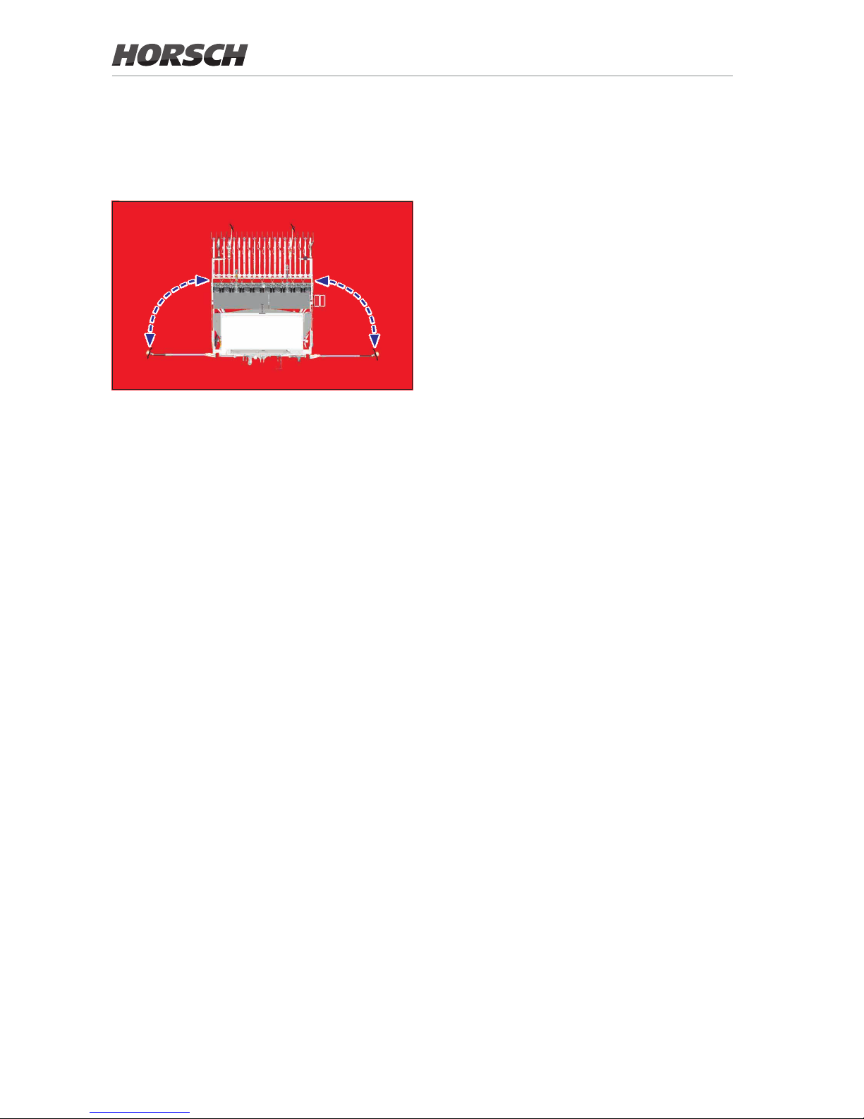
Danger zone
The area marked red indicates the danger zone
of the machine:
The danger zone around the machine poses the
following endangerments:
• Accidental operation of the hydraulic system
can trigger dangerous movements of the
machine.
• With the drive still running, machine parts may
rotate or swing out.
• Hydraulically raised machine parts can lower
slowly and unnoticed.
Failing to pay attention to the danger zone can
result in severe or even fatal physical injuries.
¾ Do not stand under lifted loads. Lower such
loads to the ground rst.
¾ Instruct persons to leave the danger zone
around the machine and tractor before any
machine movements.
¾ Before working in the danger zone of the ma-
chine or between machine and tractor: Shut
down the tractor!
This also applies for short-term inspection work.
Many accidents happen because of carelessness and running machines!
¾ Pay attention to the information in all operat-
ing instructions.
14
Page 19
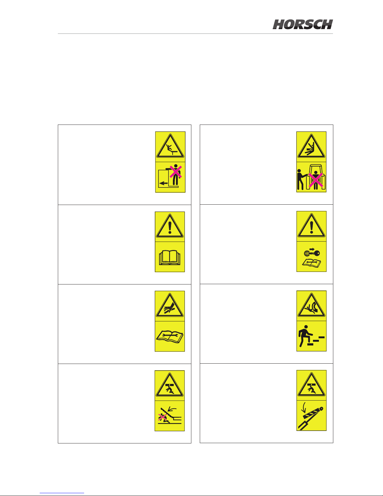
Safety stickers
Safety stickers on the machine warn of hazards
at dangerous points and are an important part
of the safety equipment of the machine. Missing safety stickers increase the risk of severe or
even fatal injuries.
¾ Clean soiled safety stickers.
¾ Damaged or illegible safety stickers must be
replaced immediately.
¾ Ax the specied safety stickers on spare
parts.
No passengers are allowed to
ride on the machine!
00380054
Before commissioning the machine you need to read and follow the operating instructions!
00380055
Caution for uids spraying out
under high pressure, follow the
notes in the operating instructions!
00380133
Stay clear of the operating
range of foldable machine parts!
00380135
When connecting the machine
and when operating the hydraulics, no persons are allowed
between the machines.
00380145
Shut the engine down and pull
o the key before starting maintenance and repair work.
00380294
Do not climb on rotatable parts.
Use mounting steps provided
for this purpose.
00380299
Remaining in the danger zone
is only permitted when the lifting
cylinder pin is inserted.
00380896
15
Page 20
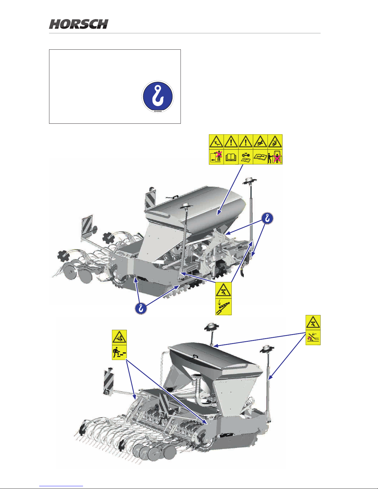
Loading hook;
hook the load suspension gear (chains,
ropes etc.) into this loading hook during
loading.
Position of safety stickers
16
Page 21
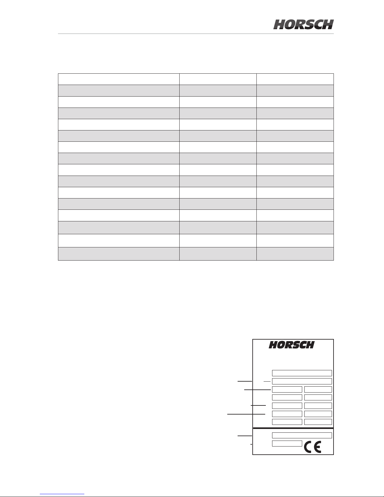
Technical data
Express 3 TD 3.5 TD
Working width (m) 3.00 3.50
Transport width (m) 3.00 3.50
Filling height (m) 2.21 2.21
Length without pre-emergence markers (m) 3.67 3.67
Length with pre-emergence markers (m) 4.00 4.00
Weight from (kg) 2 600 2 965
Seed hopper capacity (l) 1 500 1 500
Filling opening dimension (m) 0.88 x 2.42 0.88 x 2.42
Number of coulters 20 24
Coulter pressure of seed coulter (kg) 5 - 120 5 - 120
Ø Coulter (cm)
34 34
Ø Press rollers (cm)
32 32
Row spacing (cm) 15 14.5
ø FarmFlex Packer (cm)
54 54
Working speed (km/h)
10 - 20 10 - 20
NOTE:
• Deviations due to technical further development reserved.
• The weight of the implement depends on the equipment; specication with minimum equipment
• The permissible transport heights and transport width for road trac may dier from country to country. Comply with
the national registration regulations.
Type plate
The type plate with the CE marking is located
on the frame of the machine.
Data on the type plate:
Serial number
Permissible total
weight
Drawbar load (= DL)
Axle load
Machine type
Year of construction
!"#$ %&'()"#
*+,('-./'(01(&.
23 ,('-./'(0(4(
17
Page 22

Requirements on the
tractor
WARNING
Risk of accident!
¾ Observe the permissible values of the tractor
for axle loads, total weight, tyre load bearing
capacity and air pressure.
¾ Verify the suitability of the tractor before com-
missioning.
The tractor must meet the following requirements to be able to use the machine as intended:
Implement attachment *
Express 3 TD 3.5 TD
Three-point Cat. III/III Cat. III/III
* Implement attachment Cat. III/III: - Upper link Cat. III with bolt ø 32 mm
- Tractor link arm Cat. III with bolt ø 37 mm
Engine power
Express 3 TD 3.5 TD
min. (kW / HP) 90 / 125 105 / 145
max. (kW / HP) 140 / 190 160 / 220
Electrics / Control system
Electric power supply 12 V
Road lighting equipment:
Socket, 7-pin, see chapter Lighting
Control ISOBUS socket
18
Page 23

Hydraulics
Maximum system pressure 210 bar
Oil grade Mineral hydraulic oil
Delivery rate 20-25 l/min at 180 bar
Control units, double-acting
- Direct drive fan (option) 1
- DiscSystem adjustment (auxiliary equipment) 1
- Bout marker (auxiliary equipment) 1
- Coulter pressure adjustment (auxiliary equipment) 1
Pressureless return ow (max. 5 bar) 1 (with direct drive fan)
PTO-shaft
Speed max. 1 ,000 rpm
19
Page 24
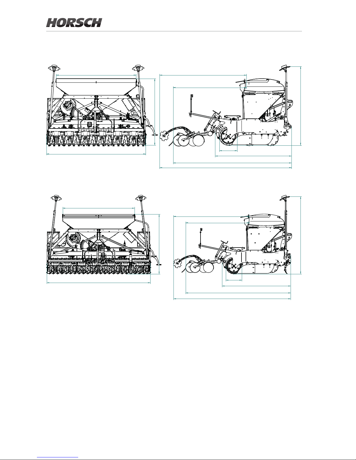
Express 3 TD
Express 3.5 TD
2420 2630
4000
2220
2310
3590 to 3670 (with harrow tines)
3000
2020
2400
ø 540
3500
2550
2140
2310
4000
3545 to 3670 (with harrow tines)
540
2420
2010
2615 to 2630
20
Page 25
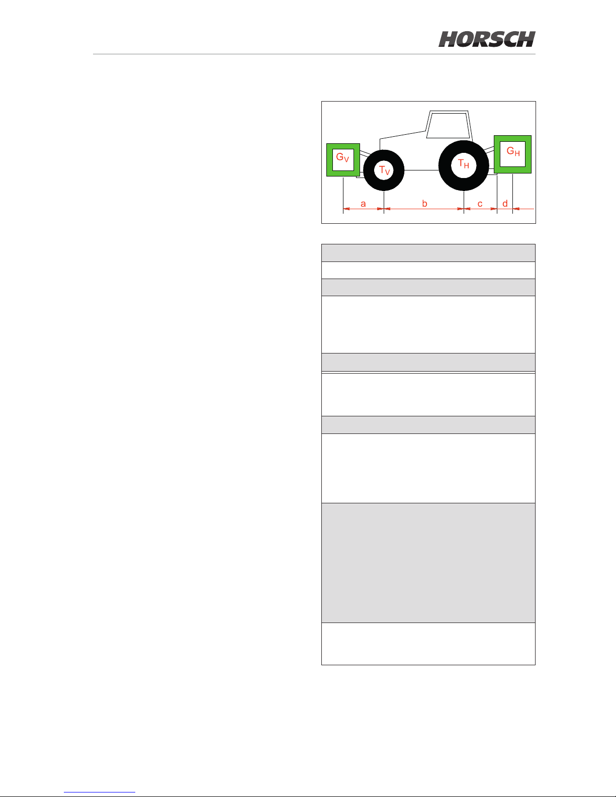
Calculating the ballasting
The permissible total weight, the permissible
axle loads and the load bearing capacity of the
tyres must not be exceeded when mounting or
hitching up implements.
The front axle of the tractor must always be
loaded with at least 20 % of the curb weight of
the tractor.
¾ Before transportation on public roads you
must make sure that the tractor is not overloaded and suitable for this implement.
¾ Weigh the implement separately. Since dif-
ferent equipment variants are possible, the
weight of the implement must be determined
by weighing.
Required data:
T
L
Curb weight of tractor
T
V
Front axle load of empty tractor
T
H
Rear axle load of empty tractor
G
H
• Total weight of rear implement
• In case of towed machines:
Maximum permissible drawbar load
for road transport.
G
V
Total weight of front implement
a
Distance from centre of gravity of front
implement (front ballast) to middle of
front axle
b
Tractor wheel base
c
• Distance from middle of rear axle to
middle of tractor link arm ball
• In case of towed machines:
Distance from middle of rear axle to
middle of hitch-up point.
d
• Distance from middle of tractor link
arm ball to centre of gravity of rear
mounted implement (rear ballast)
Concerning the centre of gravity
see chapter "technical data"; if necessary pay attention to the correct
choice of the centre of gravity.
• The following applies with towed
machines: d = 0
x
Information of tractor manufacturer for
minimum rear ballasting. If no information is available, enter 0.45.
All specied weight in (kg)
All specied dimensions in (m)
21
Page 26
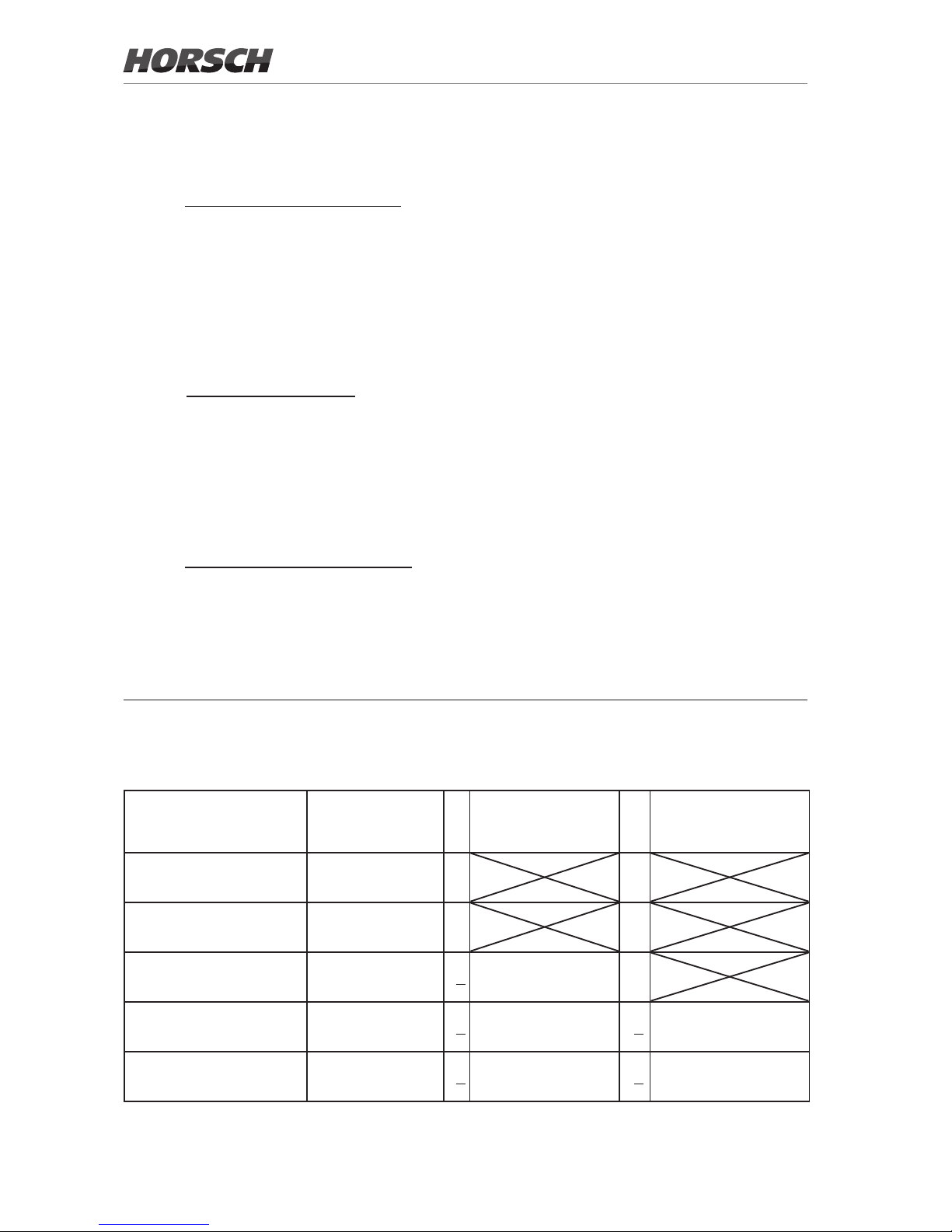
Table
The calculated values must not exceed the permissible values.
Actual value as
calculated
Permissible value
from operating instructions
Two-times the permissible tyre load
bearing capacity
Minimum ballasting front
(with rear implement)
G
V min
= kg
Minimum ballasting rear
(with front implement)
G
H min
= kg
total weight
G
tat
= kg < kg
Front axle load
T
V tat
= kg < kg < kg
Rear axle load
T
H tat
= kg < kg < kg
1. Calculation of minimum front ballasting
with rear implement:
Enter the result into the table.
2. Calculation of minimum rear ballasting
with front implement:
Enter the result into the table.
3. Calculation of the real front axle load
Enter the result of the calculated actual front axle
load and the permissible front axle load from the
operating instructions of the tractor into the table.
GH• (c + d) - TV • b + 0.2 • TL • b
a + b
G
V min
=
GV• a - TH • b + x • TL • b
b + c + d
G
H min
=
GV• (a + b) + TV • b - GH •(c + d)
b
T
v tat
=
4. Calculation of the actual total weight
Enter the result of the calculated total weight and
the permissible total weight from the operating
instructions of the tractor into the table.
5. Calculation of the real rear axle load:
Enter the result of the calculated actual rear axle
load and the permissible rear axle load from the
operating instruction of the tractor into the table.
Checking the calculation
Check the calculated values additionally be
weighing:
Weigh the front axle load and the rear axle load
on the entire tractor (with implement and ballasting). Compare the measured values with the
permissible values:
• permissible total weight
• maximum front and rear axle load
• Minimum front axle load (20 % of the tractor's
deadweight)
GV + TL + G
H
G
tat
=
G
tat
- T
V tat
T
H tat
=
22
Page 27
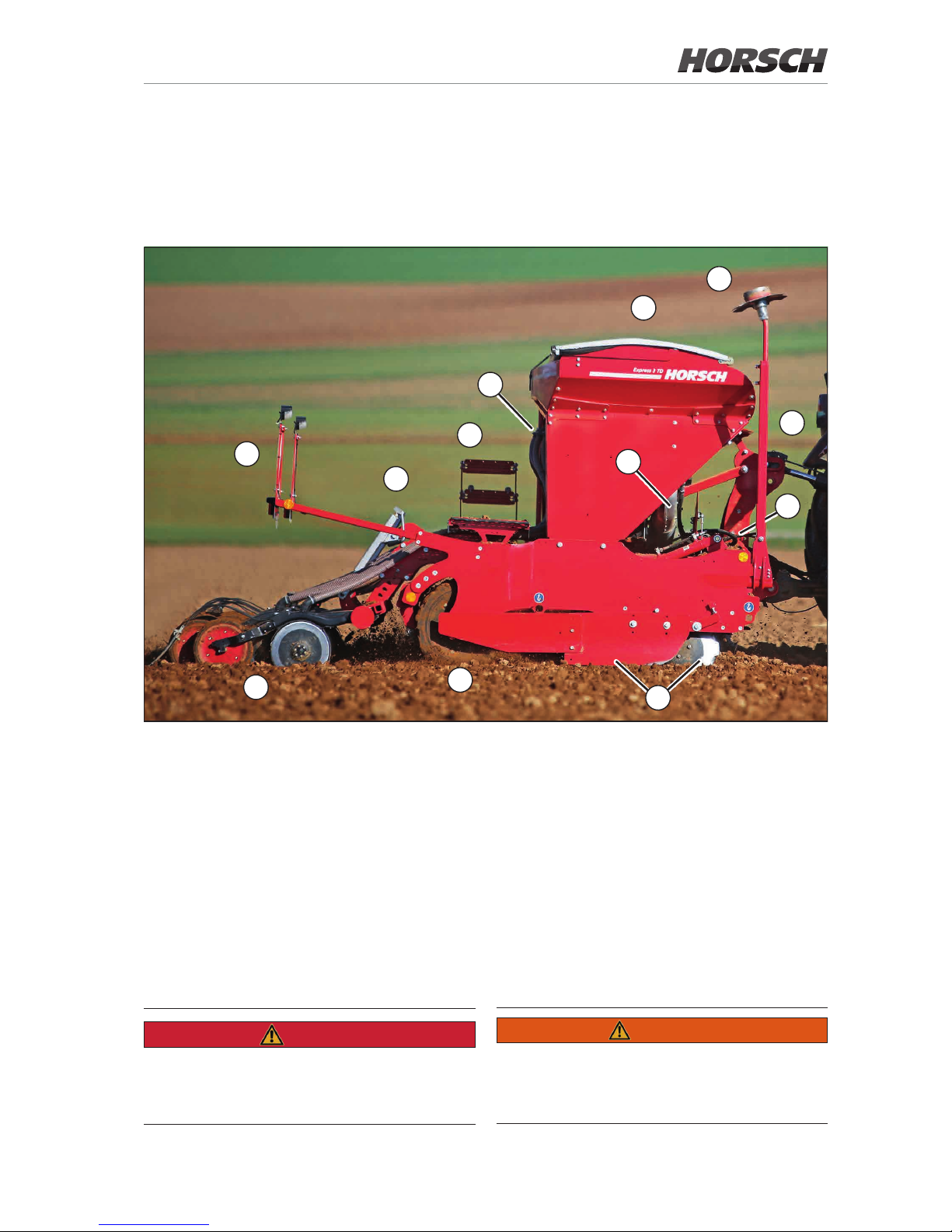
Design
Overview
1
3
4
5
6
7
11
10
2
8
12
9
Express TD
1 Three-point implement attachment
2 DiscSystem, two-row
3 Packer
4 Coulter
5 Lighting
6 Coulter pressure adjustment
WARNING
Danger of injury
¾ Do not look into the near-area of the radar
sensor (12).
7 Access step and platform
8 Distributor
9 Fan
10 Hopper
11 Bout marker
12 Radar sensor
DANGER
Danger of serious accidents
Transport rides on the machine, especially the
access step and platform (7) are prohibited!
23
Page 28
Hydraulics
WARNING
Accidental hydraulic movements (e.g. caused
by passengers or children) can lead to severe
accidents and injuries!
¾ Secure or lock the control units on the tractor.
¾ Instruct persons to leave the slewing range of
foldable machine parts.
¾ Switch all control units to the locked position
before switching on the tractor again.
NOTE
¾ Operate the machine with mineral oils.
Do not mix mineral oils with organic or ester
oils!
The hydraulic circulation of the tractor must
contain mineral-based hydraulic oil.
¾ Oil purity acc. to ISO 4406: 18/16/13
¾ Always plug in all hydraulic lines! Otherwise
components may get damaged because of
interrelated functions.
¾ Ensure cleanliness and tight t of all plug-and-
socket connections!
¾ Observe the notes on hydraulics and pressure
accumulator in chapter Safety and responsibility!
Identication of hydraulic
hoses
The symbol is always located above the hose
that requires pressure to bring the machine in
transport position (lift out, folding, etc.).
Fan
Bout marker
Tools (coulter pressure adjustment / DiscSystem
options)
24
Page 29
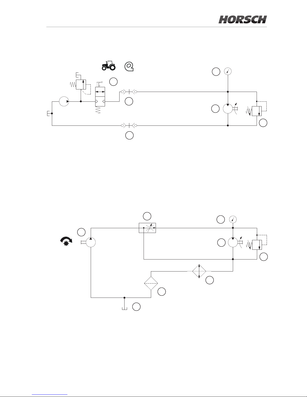
Fan - direct drive
1 Tractor control unit
2 Hydraulic coupling, ow
3 Hydraulic coupling, return
4 Pressure gauge
5 Geared motor 6 cm³
6 Pressure limiting valve (in the engine)
A
B
2
3
1
4
5
6
Fan - PTO-shaft drive
1 Gear pump 61 cm³
2 Flow control valve
3 Pressure gauge
4 Geared motor 11 cm³
5 Pressure limiting valve (in the engine)
6 Oil cooler
7 Return lter
8 Hopper
1
2
3
4
5
6
7
8
A
A
P
B
B
25
Page 30
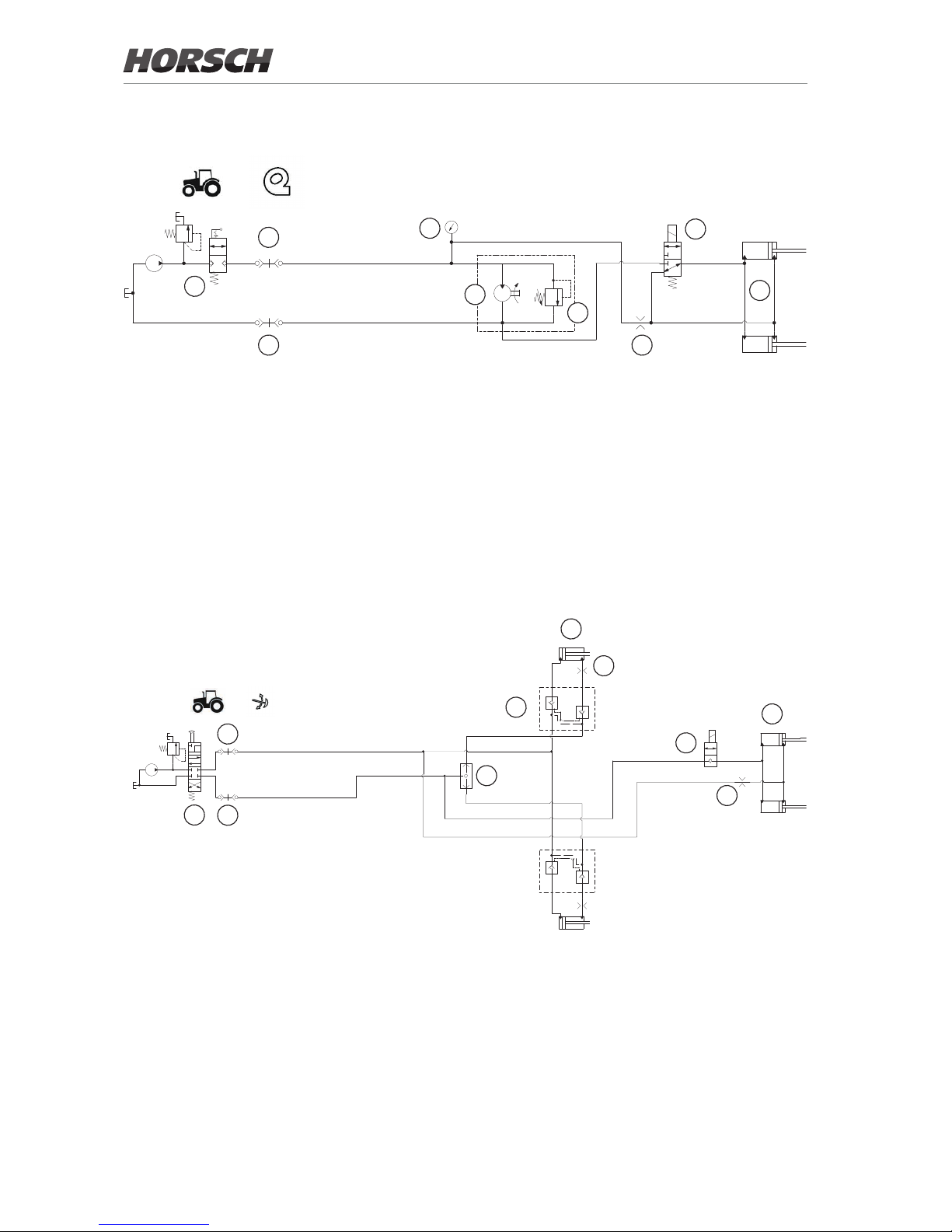
Pre-emergence markers and bout marker
1 Tractor control unit
2 Hydraulic coupling - unfolding
3 Hydraulic coupling - folding
4 Bout marker shuttle valve
5 Double acting lock valve
6 Hydraulic cylinder bout marker
7 Throttle ø 1.5 mm (only with pre-emergence markers auxiliary equipment)
8 2/2 way valve (only with pre-emergence markers auxiliary equipment)
9 Hydraulic cylinder pre-emergence markers (only with pre-emergence markers auxiliary equipment)
12
1
4
3
2
6
5
9
7
7
8
C1 C2
V1
V2
V1
V2
C1
C2
1 2
A
P/T
B
Direct drive fan with pre-emergence markers (without bout marker)
1
3
2
5
6
7
8
4
9
A
1
3
2
B
1 Tractor control unit
2 Hydraulic coupling, ow
3 Hydraulic coupling, return
4 Pressure gauge
5 Geared motor 6 cm³
6 Pressure relief valve
7 Restrictor ø 1 mm
8 3/2-way valve
9 Hydraulic cylinder pre-emergence marker
26
Page 31
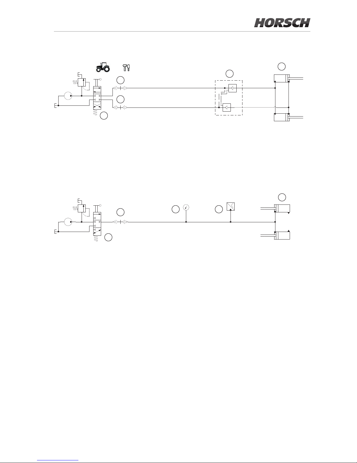
Hydraulic depth settingDiscSystem
1 Tractor control unit
2 Hydraulic coupling - lower
3 Hydraulic coupling - lift
1
2
3
4
5
V1
V2 C2
C1
4 Double acting lock valve
5 Hydraulic cylinders
Hydraulic coulter pressure adjustment
1
2
3 4
5
1 Tractor control unit
2 Hydraulic coupling
3 Pressure gauge
4 Switch for work signal
5 Hydraulic cylinders
27
Page 32
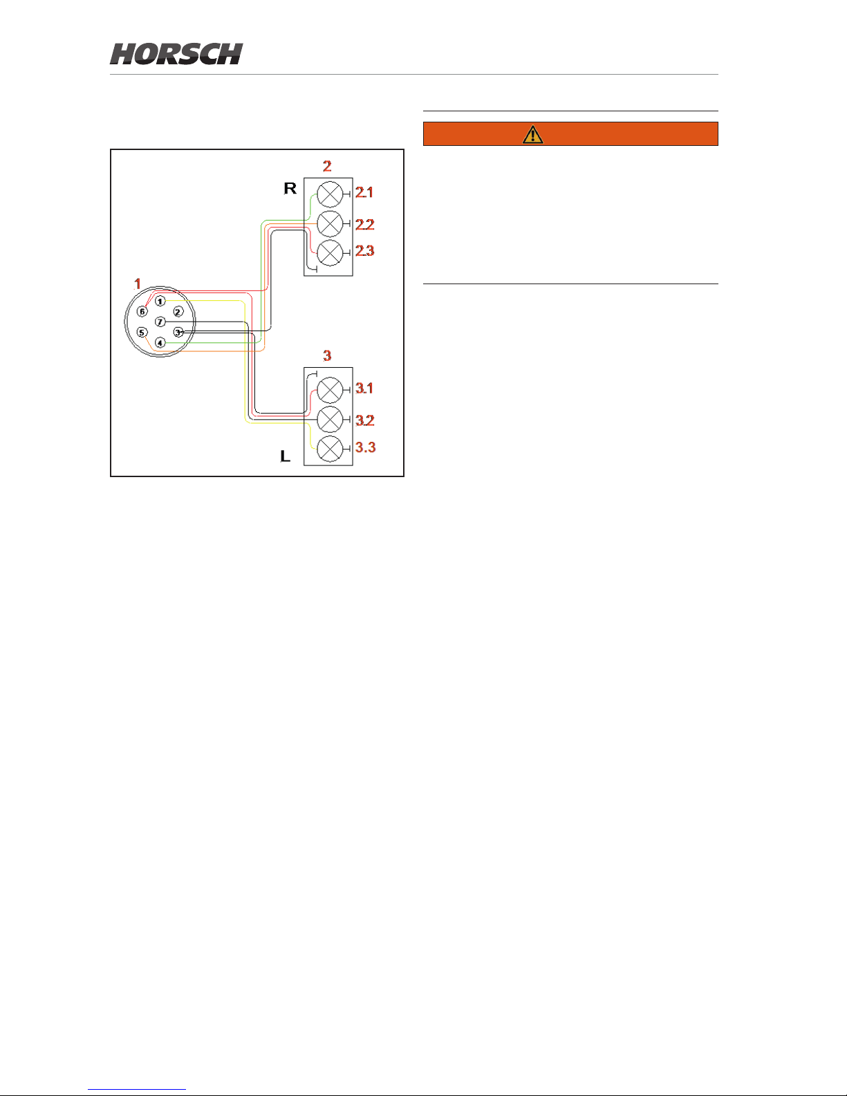
Lighting
1. 7-pin plug
2. Rear light, right
2.1 Lamp, direction indicator
2.2 Lamp, tail light
2.3 Lamp, brake light
3. Rear light, left
3.1 Lamp, brake light
3.2 Lamp, tail light
3.3 Lamp, direction indicator
Plug and cable assignment
No. Desig. Colour Function
1 L yellow Indicator left
2 54 g -- -3 31 white Earth
4 R green Indicator right
5 58 R brown Rear light, right
6 54 red Brake light
7 58 L black Rear light, left
WARNING
Trac accidents caused by defective lighting.
¾ Ensure cleanliness and tight t of the plug-
and-socket connections.
¾ Check the lighting before setting o.
¾ Check warning boards and lighting equipment
for cleanliness.
28
Page 33
Instruction stickers
¾ Clean soiled stickers.
¾ Damaged or illegible stickers must be re-
placed immediately.
¾ Apply the specied stickers to spare parts.
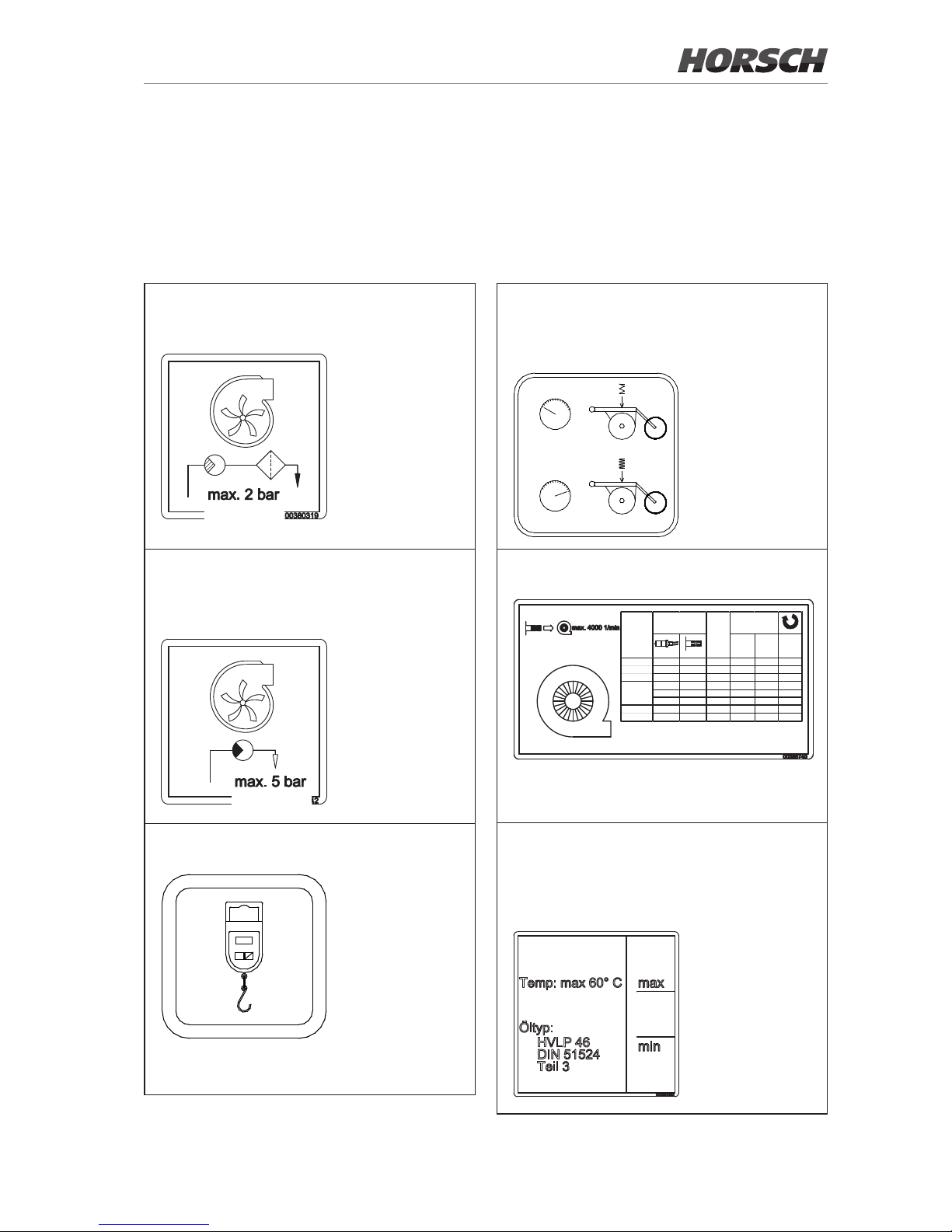
If the return ow pressure exceeds 2 bar
replace the lter and change the oil.
The return ow pressure at the fan drive
must not exceed 5 bar, as otherwise the
hydraulic motor may be destroyed.
Attach the scales here when calibrating.
00380879
OFF
ON
ZERO
Hydraulic coulter pressure adjustment
The increase of the coulter pressure is
indicated on the pressure gauge.
0
0
+
bar
bar
Fan speeds
<150 >150 1/min
3 KR o x 2500
3,5 KR o x 3200
4 KR o x 3500
o ox 2500
oo x 3200
oo x 3500
Singular o x x x 4000
Sy stem o xxx≥4000
3 TD
3,5 TD
12
km/h
Gebläseantrieb
Fan drive
Fein-
saaten
-
Fine
seeds
Getreide (kg/ha)
Grain (kg/ha)
Observe the oil type and maximum temperature.
The lling level in the hopper must be between min. and max.
max. 2 bar
max. 5 bar
29
Page 34

Hitching / uncoupling
(only for France)
00380900
„ Atteler à un tracteur dont le relevage est équipé
de dispositifs de blocage latéraux et verticaux“.
„Pour circuler sur la route, respecter la hauteur
d’attelage spécifiée dans la notice d’utilisation
et bloquer le relevage“.
O
O
Driving with empty seed hopper
(Only for France)
00380885
rouler avec
trémie vide“
“
30
Page 35
Commissioning
NOTE
These work activities may be carried out only by
persons trained by HORSCH for this purpose.
WARNING
Increased danger of accidents during commissioning.
¾ Observe the notes in the safety chapter.
Delivery
The machine with implements is normally delivered completely assembled on a low loader.
If parts or assembly groups had to be disassembled for transport purposes, these will be
assembled locally by our distributor or eld
technician.
Depending on the design of the low loader the
machine can be unloaded with a tractor, or
needs to be lifted o with suitable lifting gear
(forklift truck or crane).
¾ Use only lifting equipment and lifting gear with
adequate lifting capacity and approval!
Lifting and lashing points are identied by labels.
When using other lifting points pay careful attention to the centre of gravity and the weight
distribution. These points must, in any case, only
be on the frame of the machine.
Transport
Depending on country-specic regulations and
working width the equipment can be transported
on public roads either attached to a tractor or on
a trailer or low loader.
¾ The permissible dimensions and weights for
transport must be complied with.
¾ The tractor must be large enough so that
sucient steering and braking abilities are
ensured.
¾ If the machine is hitched up in two-point mode,
the tractor link arms must be blocked against
swinging sideways.
¾ On a trailer or low loader the machine must
be secured with tensioning straps or other
means.
¾ Attach lifting tackle only at the marked points.
¾ Pay attention to the notes in the Ballasting
chapter.
Installation
Instruction of the operator and initial installation
of the machine will be carried out by our service
technicians or distributors.
Any preceding use of the machine is prohibited!
The machine can only be released for operation after the instruction session conducted by
our service technician / distributor and after the
operating instructions have been read.
WARNING
Increased danger of accidents during installation
and maintenance.
¾ Read these operating instructions and become
acquainted with the machine before starting
this work.
Depending on scope of equipment
¾ Take loosely delivered parts o the machine!
¾ Check all important screw connections!
¾ Lubricate all grease nipples!
¾ Check air pressure in tyres.
¾ Check all hydraulic connections and hoses
for correct fastening and function!
¾ Immediately rectify any occurring damage or
have it corrected!
Installation of the drill controls is described
in the corresponding instruction manual.
31
Page 36
Operation
Whenever working on the machine
pay attention to the associated safety
notes in the chapter "Safety and
prevention of accidents" as well as
the accident prevention instructions!
Connecting/Parking
DANGER
There is a risk that persons may become
crushed and severely injured between machine
and tractor!
¾ Instruct persons to leave the area between
tractor and machine.
No person must be present between machine
and tractor when the tractor approaches the
machine or moves away from it!
DANGER
Danger of severe accidents when manoeuvring.
Keep an eye on your environment.
¾ Keep persons (children) out of the manoeu-
vring range of the machine.
WARNING
Leaking hydraulic uid can cause serious injuries! Danger of injury by unwanted machine
movements.
¾ Connect and disconnect the hydraulic lines
only when the hydraulics have been de-
pressurized on both machine and equipment
sides.
Connecting
1. Clean the towing facilities of machine and
tractor and check for wear.
2. Move the tractor to the machine and set the
brake.
3. Couple the machine to the three-point of the
tractor.
- Pick up the machine by the tractor link
arm.
- Insert the securing device of the catching
hooks.
- Lock the tractor link arms against move-
ment sideways.
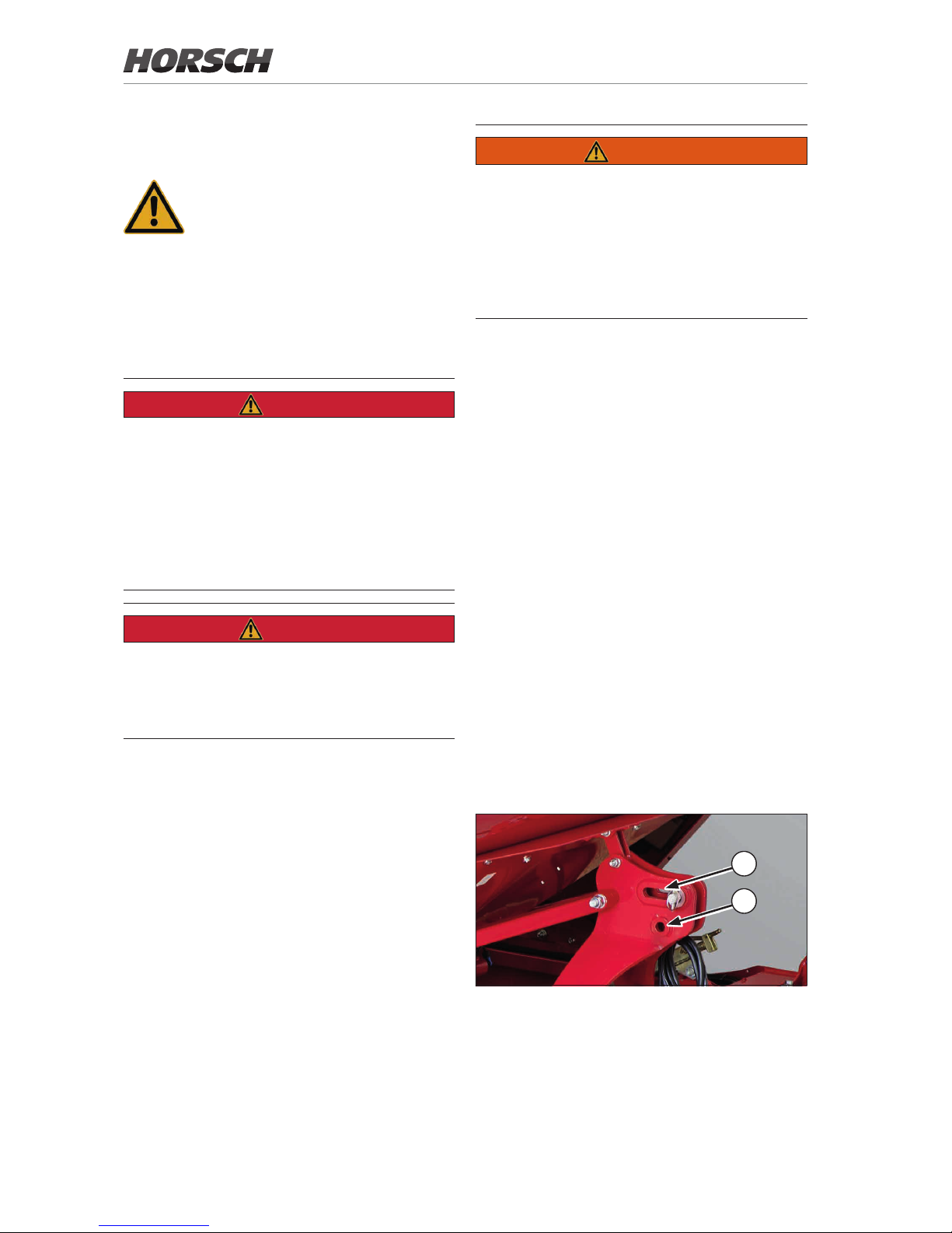
- Hook the upper link into the bore (1) and
secure with cotter pin (three-point hydrau-
lics in oating position).
The upper link can be connected to the
slotted hole (2) for very light soils that can
be pushed or under wet conditions (threepoint hydraulics in position control).
2
1
4. Connect the hydraulic lines, see chapter
Hydraulics.
32
Page 37
5. For fan with PTO-shaft drive:
- Plug the PTO-shaft pump on the PTOshaft journal of the tractor.
- Secure the PTO-shaft pump with the
bracket against twisting, see chapter
Pneumatics.
6. Connect lighting and ISOBUS.
7. Turn the support upward and secure it with
bolt and cotter pin.
8. Check before starting to drive whether the
machine has been properly connected and
secured.
Transport position
WARNING
Danger of road accidents caused by losing the
machine or machine parts.
¾ Lock the control units mechanically or elec-
trically, depending on the version, during
transport travel. Never switch them to the
oating position.
¾ Check all interlocks before starting to drive.
¾ Check whether all securing elements of the
connection are in place as set correctly.
¾ Check components of the connection for
wear.
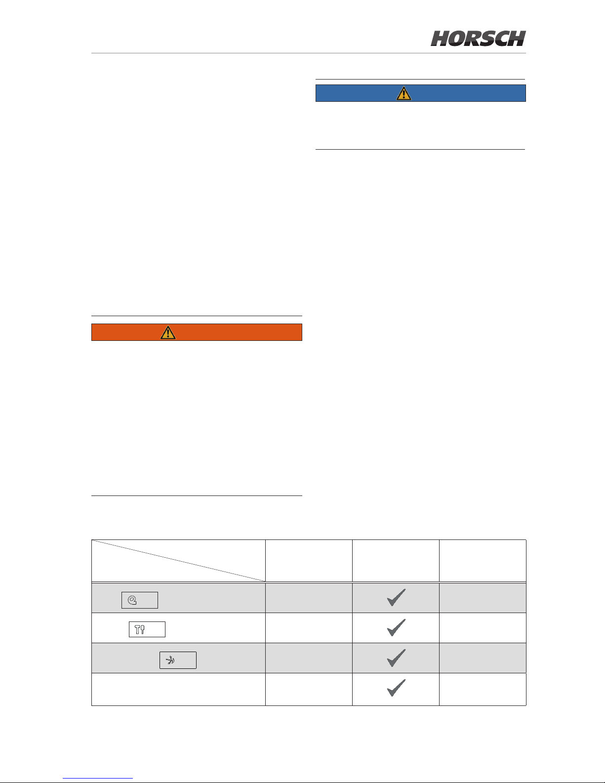
Position
Control unit
Floating position Locked position Supply
Fan
Tools
Bout marker
Three-point hydraulics
Position of the control units during road travel
NOTE
¾ Make sure before driving on public roads that
the machine meets all respective applicable
road trac regulations.
Make the following additional adjustments before road transport:
1. Lift the machine.
2. Fold up the bout markers.
3. Fold up the access steps.
4. Switch o the E-Manager.
33
Page 38

Parking
DANGER
Risk of accident due to insucient stability
¾ Park the machine on a at and paved surface.
NOTE
Before parking for an extended period:
¾ Park the machine in a hall or under a roof.
¾ Clean the machine and prepare it accordingly,
see chapter Care and maintenance.
1. Position the machine at a suitable location
and set the tractor brake.
2. Lock the control units.
3. Disconnect hydraulic and electrical connections and place them into the hose cabinet.
4. Turn the support down and secure it with bolt
and cotter pin.
5. Empty the seed hopper.
6. Relieve and uncouple the upper link.
7. Uncouple the tractor link arm and lower it.
8. For fan with PTO-shaft drive:
- Switch o the PTO-shaft.
- Remove the PTO-shaft pump and hook it
in the bracket.
9. Reduce the coulter pressure adjustment to
relieve the rubber elements.
10. Empty and clean the metering unit.
11. Lock the seed hopper cover.
12. Store the terminal in dry conditions.
34
Page 39
Use in the eld
1. Connecting the machine, see Connecting. Ad-
just the lifting point of the upper link according
to the eld conditions.
2. Adjusting and checking the working depth
of the DiscSystems and the track loosening
discs, see Settings.
3. If so equipped, adjust the working depth of the
track loosening tines, see Auxiliary equipment.
4. Adjusting the drilling depth and the coulter
pressure on the coulters, see Settings.
5. Adjusting the harrow, see Settings.
6. If so equipped, adjust the pre-emergence
markers and bout markers, see Auxiliary equip-
ment.
7. Fold up the steps.
8. Adjusting the fan speed, see Pneumatics.
NOTE
Please note:
• To control the seed refer to the operating
instructions for the E-Manager
• The machine must be in horizontal position
when used in the eld.
• Do not drive backwards with the machine
lowered.
The components have only been designed for
forward travel in the eld and may be damaged when reversing.
Position of the control units during use in the eld
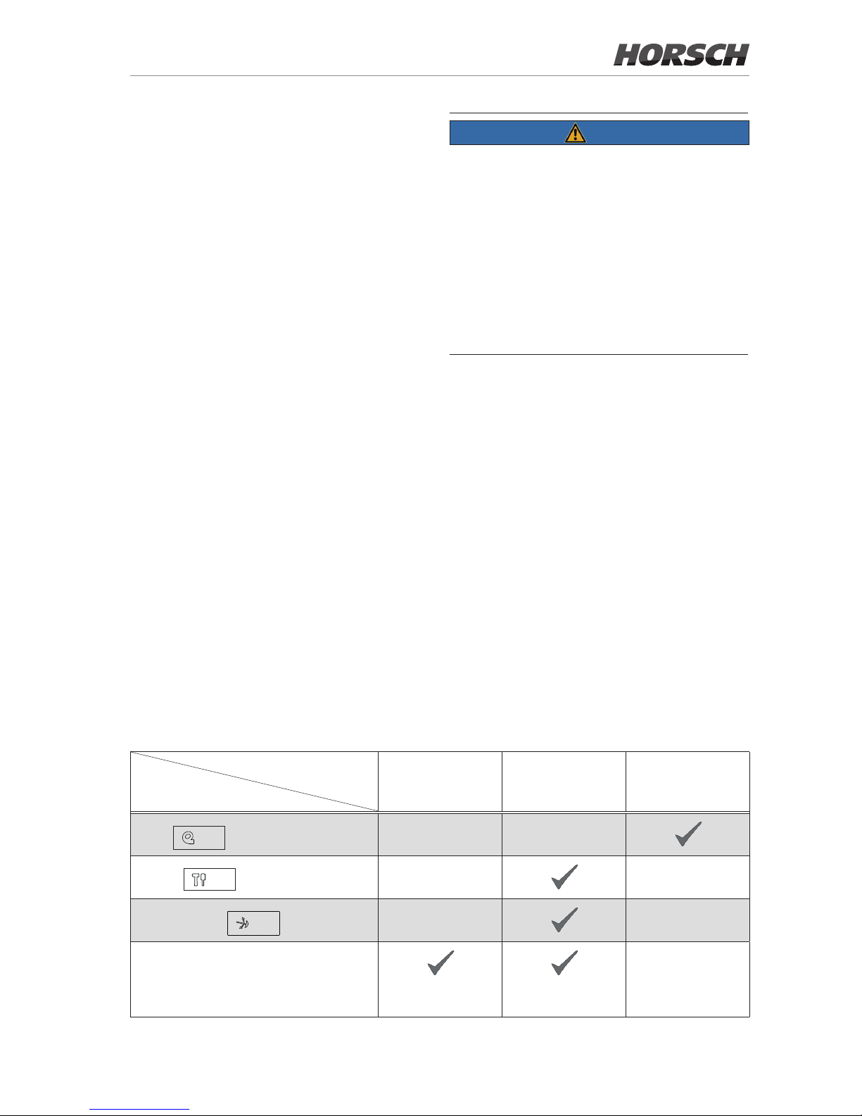
Position
Control unit
Floating position Locked position Supply
Fan
Tools
Bout marker
Three-point hydraulics
Upper link connected
to the hole
Upper link connected
to the slotted hole
35
Page 40

Working speed
The working speed depends on the eld conditions (soil type, crop residues etc.), seed, seed
quantity, coulters and other factors.
NOTE
¾ Operate somewhat slower under difficult
conditions.
Headland
¾ Lift out the machine and move the coulter
upward.
¾ Fold the bout marker.
¾ After turning lower the coulter approx. 2 - 5 m
in front of the seedbed with pressure at the
appropriate fan speed. The seed requires
some time to ow from the metering unit to
the coulters.
The working switch only releases the signal after the machine has been lowered completely.
¾ Unfold the bout marker.
By means of a shuttle valve the bout marker
is unfolded in each case automatically on the
other machine side.
NOTE
When drilling reduce the seed just before lifting
out the machine.
Otherwise the fan output would be excessively
reduced and the hoses might get blocked.
Checks
NOTE
¾ Check the placement quality when beginning
to work (after a few metres of drilling) and with
larger elds also in between on all coulters:
• Drilling depth
• Longitudinal distribution of the seed
• Transverse distribution of the seed
The sowing quality essentially depends on the
adjustments and checks made prior to and
during drilling, as well as on regular care and
maintenance of the machine.
¾ Carry out all maintenance tasks and adjust-
ments before starting to work.
Machine
¾ Has the machine been hitched up correctly
and are the coupling devices locked?
¾ Have the tractor link arms being locked
against swinging sideways?
¾ Have the hydraulic lines been connected
without being mixed up by mistake?
¾ Have the bout markers been set to the cor-
rect length?
¾ Has the machine been levelled in working
position and the drilling depth correctly adjusted?
Cultivation tools
¾ Are all cultivation tools still in a serviceable
state?
- DiscSystem
- Packer
- Coulter
- Harrow
- Optional equipment
¾ Are all cultivation tools adjusted correctly?
¾ Do the coulter discs still have sucient preten-
sion and turn easily?
36
Page 41

Fan
¾ Is the hydraulic fan connected to a pressure-
free return ow?
¾ Are fan wheel and intake grille clean?
¾ Is the fan wheel tightly mounted on the shaft?
¾ Is the fan speed observed?
Pneumatic system
¾ Are tram line valves installed in the correct
seed lines for the tram lines? Has the tram line
rhythm been adjusted and do the aps close?
¾ Do the seed hoses not sag and are they free
of water and deposits?
¾ Are all air lines between fan and coulters leak
tight and rmly connected?
¾ Does air ow uniformly out of all coulters?
¾ Has the air volume been set correctly on the
fan? Does the seed bounce out of the seed
furrow, or remain in the pipes and cause
blockage?
Metering unit
¾ Has the correct rotor been installed?
¾ Have the sealing lips been adjusted and are
they still serviceable?
¾ In case of small seed, has the cleaning brush
been installed and is it in order?
¾ In the case of large seed, has the scraper
been installed?
¾ Are all connections air tight and has the clear-
ing valve been closed rmly and leak free?
¾ Is seed coming out of all coulters?
¾ Is seed bridging forming in the hopper (par-
ticularly with husky seed)?
¾ Is the correct seed quantity being placed,
especially in the case of small seed?
After sowing
Empty and clean the hopper and metering unit
after sowing.
Seed and dressing may otherwise become
moist, sticky and cause seed bridging in the
hopper and the rotors. Metering and seed errors
could occur.
¾ Empty the seed hopper on the clearing valve
on the side. Place a suitable container underneath and open the discharge gate, see
chapter Hopper.
¾ Residues can be emptied through the fall
sluice.
37
Page 42
Settings
WARNING
Risk of accident from unauthorised starting of
the tractor and triggering of machine movements.
¾ Shut o the tractor before any adjustment
tasks and secure it against reactivation. Lock
manual control units in the locked position.
CAUTION
Risk of injury when working on the machine
(e.g. on edges that need to be sharp because
of their function).
Always use an appropriate protective outt for
all repair, maintenance and adjustment work.
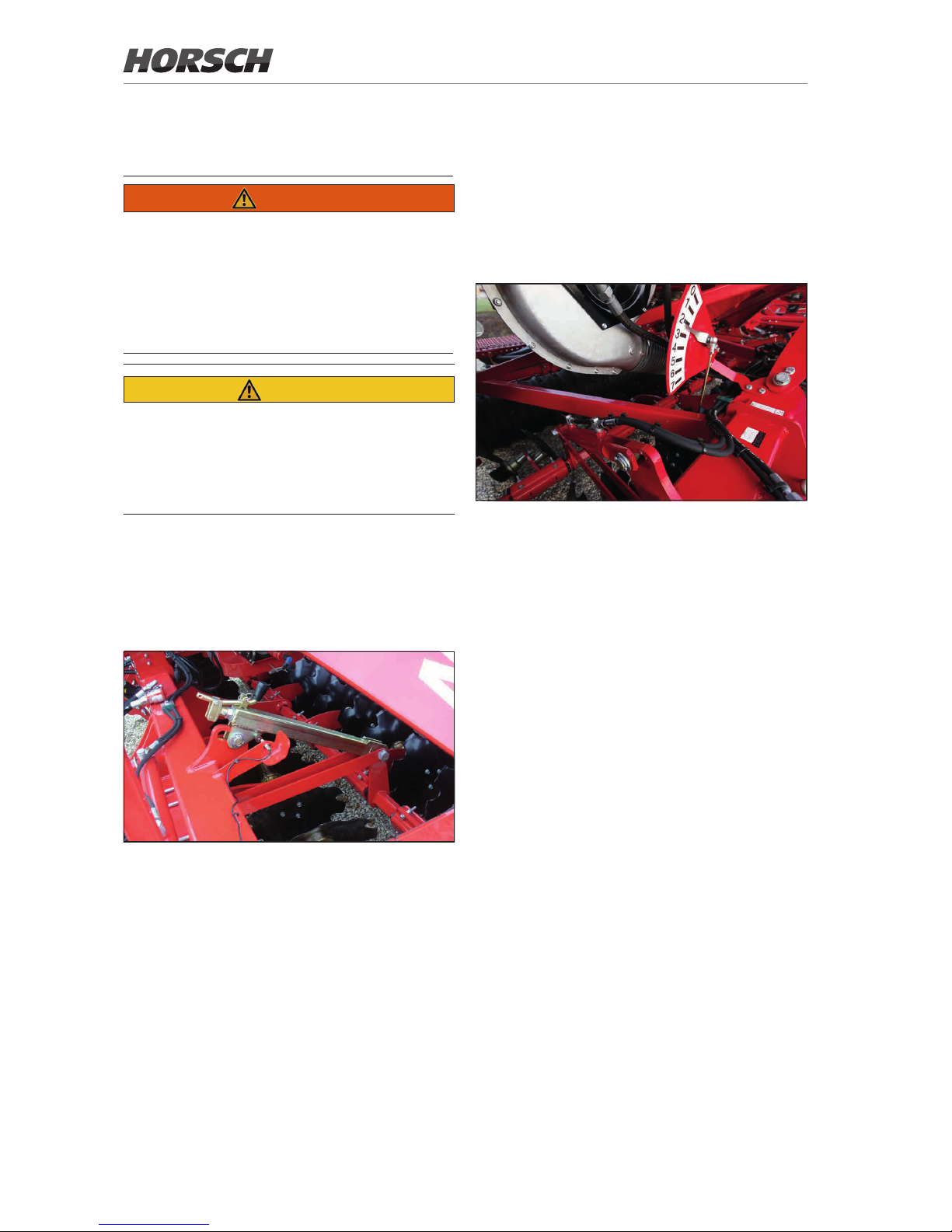
DiscSystem
The working depth of the DiscSystem must be
adapted to the soil conditions. It is adjusted via
two screw adjustments:
¾ For adjustment loosen the handle, fold it into
the guide and secure it with a cotter pin.
¾ Set both screw adjustment uniformly.
¾ Fold the handle to the parking position and
secure it with a cotter pin.
¾ Check the working results of the DiscSystem
in the eld and correct the setting, if required.
Hydraulic adjustment (option)
The hydraulic adjustment allows adjusting the
working depth of the DiscSystem innitely variable during eld work.
The setting of the DiscSystem is shown on the
scale:
Position 0: top position
...
Position 7: maximum working depth
38
Page 43
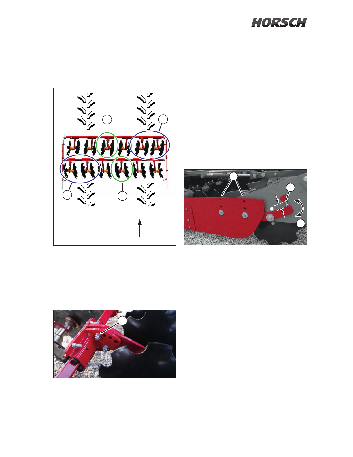
Track loosening discs
To be able to loosen and level the tractor tracks,
certain disc pairs of the DiscSystem can be set
deeper.
Direction of travel
1
1
2
2
¾ Set the outer disc pairs (1) deeper to loosen
and level the tractor tracks.
Soil is thereby moved from the tractor tracks
into the area between the tractor tracks.
¾ Set the disc pairs between the tractor tracks
(2) deeper to ll up the area between the tractor tracks again.
3
Adjustable track loosening discs
¾ Loosen and remove screw and nut (3) to make
the adjustment.
¾ Adjust the working depth of the track loosen-
ing discs through the hole pattern.
¾ Tighten screw and nut (3).
¾ Check the working results of the track loosen-
ing discs after work in the eld and correct the
setting, if required.
Side plates
The side plates prevents the formation of ridges
of soil between bouts.
The setting must be adapted to the soil conditions. No earth wall and furrow may be created
between the tracks.
3
1
a
2
¾ Check the height of the side plates after ad-
justing the DiscSystem and adapt them as
needed.
¾ Adjust the height of the plates via the rows
of holes (1).
¾ Set the incline of the plates (2).
To do so, loosen the locking nut (3) and adjust
the incline over the visible length (a) of the
screw. Tighten the locking nut.
¾ Replace the side plates if worn. The wear
limit is reached when the working result in
the lowest position is no longer satisfactory
(wall formation).
39
Page 44
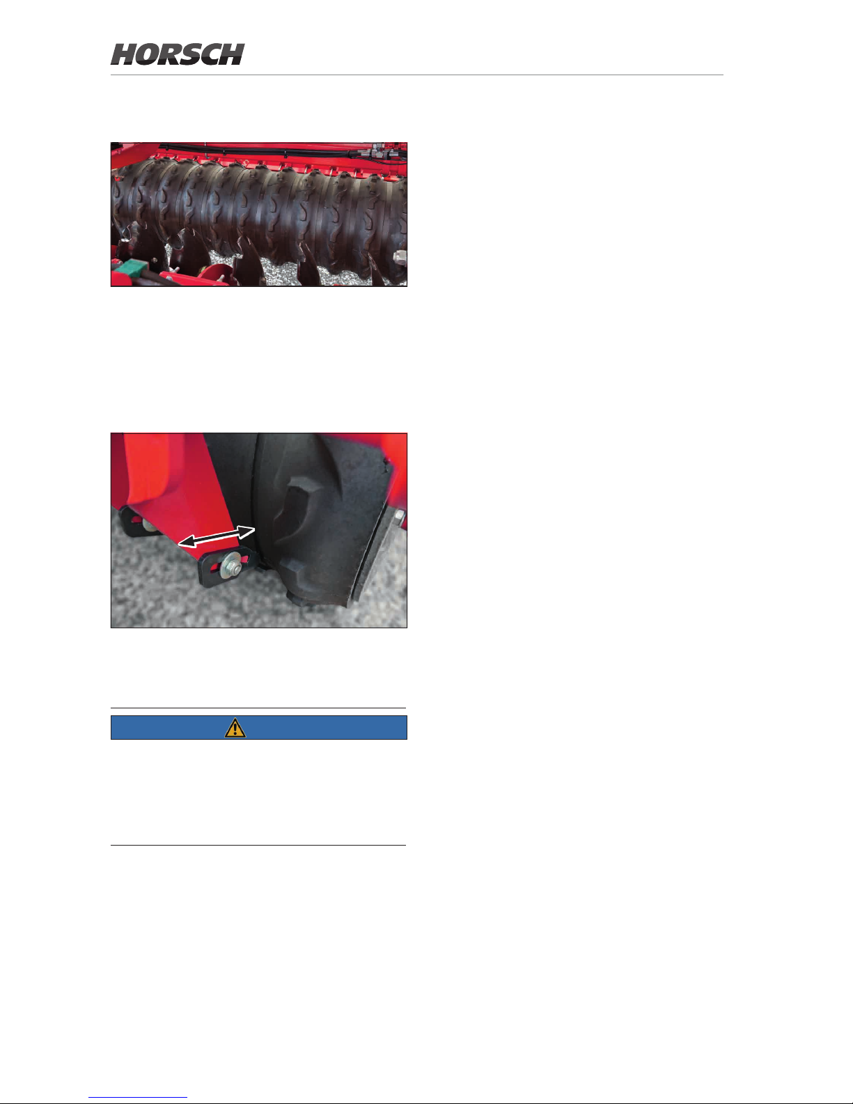
FarmFlex Packer
FarmFlex Packer
Rubber roller with excellent consolidation on
medium soils. Leaves a wavy prole.
As DoubleDisc packer insensitive to wetness.
Particularly suitable for stony soils.
Scraper
¾ Readjust the scraper via the slotted hole if
worn (approx. 5-7 mm distance to the packer).
¾
NOTE
¾ Observe the distance to the packer over the
entire circumference to avoid damages to
the packer.
The scrapers must not scrape against the
packer at any point!
40
Page 45
Pneumatic system
The pneumatic system consists of
• Fan
• Hopper
• Metering unit
• Distributor tower
WARNING
Risk from hazardous dust (fertiliser, dressing)
on the components of the pneumatic system
¾ Always wear suitable protective clothing
(safety goggles, respiratory masks, protective
gloves) for cleaning and maintenance work.
NOTE
¾ Fan setting, seed transport and seed place-
ment must be checked on all coulters when
starting sowing and also at regular intervals
when working on large areas.
Fan
CAUTION
Risk of injury on the fan
¾ Do not touch hydraulic components that have
become hot during operation.
¾ Operate the fan only while the protective grille
is mounted.
¾ Perform maintenance work on the fan and
opening of the protective grille only while the
machine is at a standstill.
The hydraulic fan is directly driven by the tractor
hydraulics.
The generated air ow conveys the seed from
the fall sluices to the coulters. The required air
quantity depends on seed (type and weight),
seed quantity, working width and sowing speed.
A correct fan speed cannot be specied and
must therefore be determined by trials in the
eld.
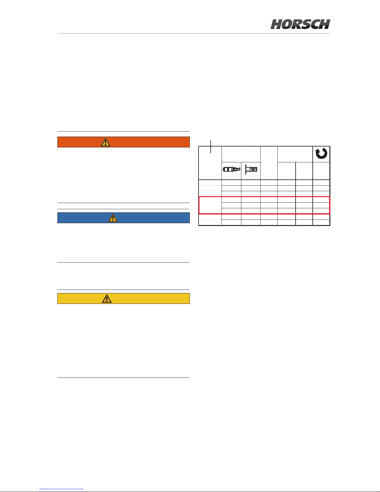
¾ Refer to the sticker on the machine as refer-
ence values for the correct fan speed:
<150 > 150 1/mi n
3 KR o x 2500
3,5 KR o x 3200
4 KR o x 3500
o ox 2500
oo x 3200
oo x 3500
Singula r o x x x 4000
S yst e m o xx x≥4000
3 TD
3,5 TD
12
km/h
Gebläseantrieb
Fan drive
Fein-
saaten
-
Fine
seeds
Getreide (kg/ha)
Grain (kg/ha)
Working speed
Fan drive
Small
seed
Grain
(kg/ha)
Please note
• To control the speed, the control unit in the
tractor must be equipped with a ow control
valve.
• The air ow must not be too high, so that no
seed or fertiliser will be blown out of the seed
furrow.
• However, the air ow must also not be too
weak, so that no seed or fertiliser will remain in
the hoses and cause blockage. The fan speed
should therefore be set as high as possible.
• Max. speed 3 500 rpm
41
Page 46
NOTE
¾ Fan wing and protective grid must be regularly
checked for dirt deposits and cleaned.
Deposits on the protective grid restrict the air
ow and thus lead to blockage in the seed
pipes.
Deposits on the fan impeller cause unbal-
ance. The bearing will thereby be overloaded
and can be damaged.
Direct drive
Fan with direct drive
The fan speed is adjusted via the oil quantity on
the ow control valve in the tractor.
The hydraulic pump must deliver sucient oil
to prevent the fan speed from dropping, even
when the tractor speed drops or other hydraulic
functions are activated.
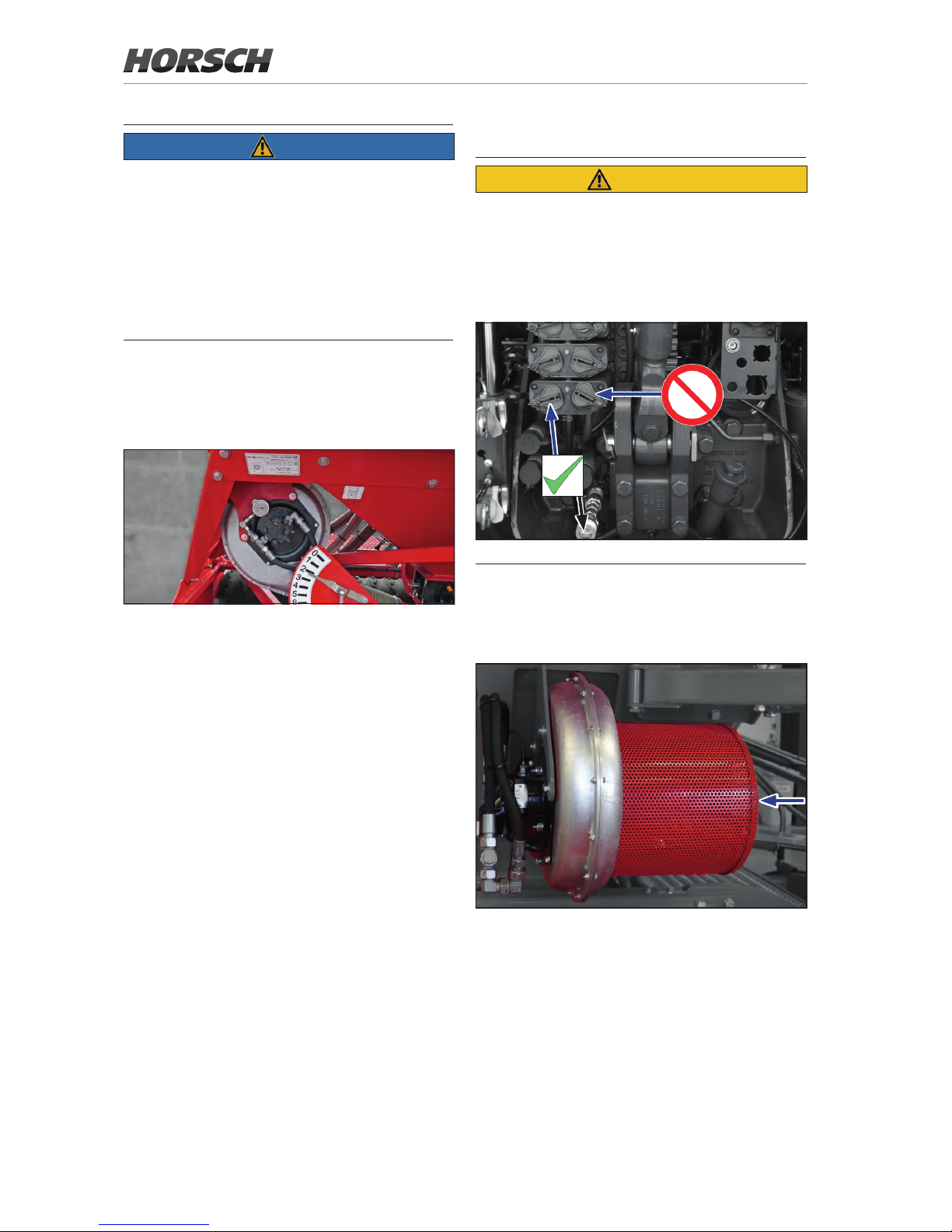
Connecting the hydraulics
CAUTION
Damage on the fan motor - gear motor
¾ Connect the return line to the pressureless
return of the tractor!
¾ Note the return ow pressure of max. 5 bar
in the leak oil line!
Gear motor connection
Checks and maintenance
¾ Let the fan only run while the protective grille
is mounted:
Fan with protective grille
¾ Clean the protective grille at regular intervals
to prevent a restriction in air ow and resulting blockage.
¾ Clean any dirt or deposits from the fan blades
to prevent unbalance and damage to impeller
and bearing.
¾ Retighten the clamping taper on the fan shaft
(see chapter Retightening the fan ange).
42
Page 47
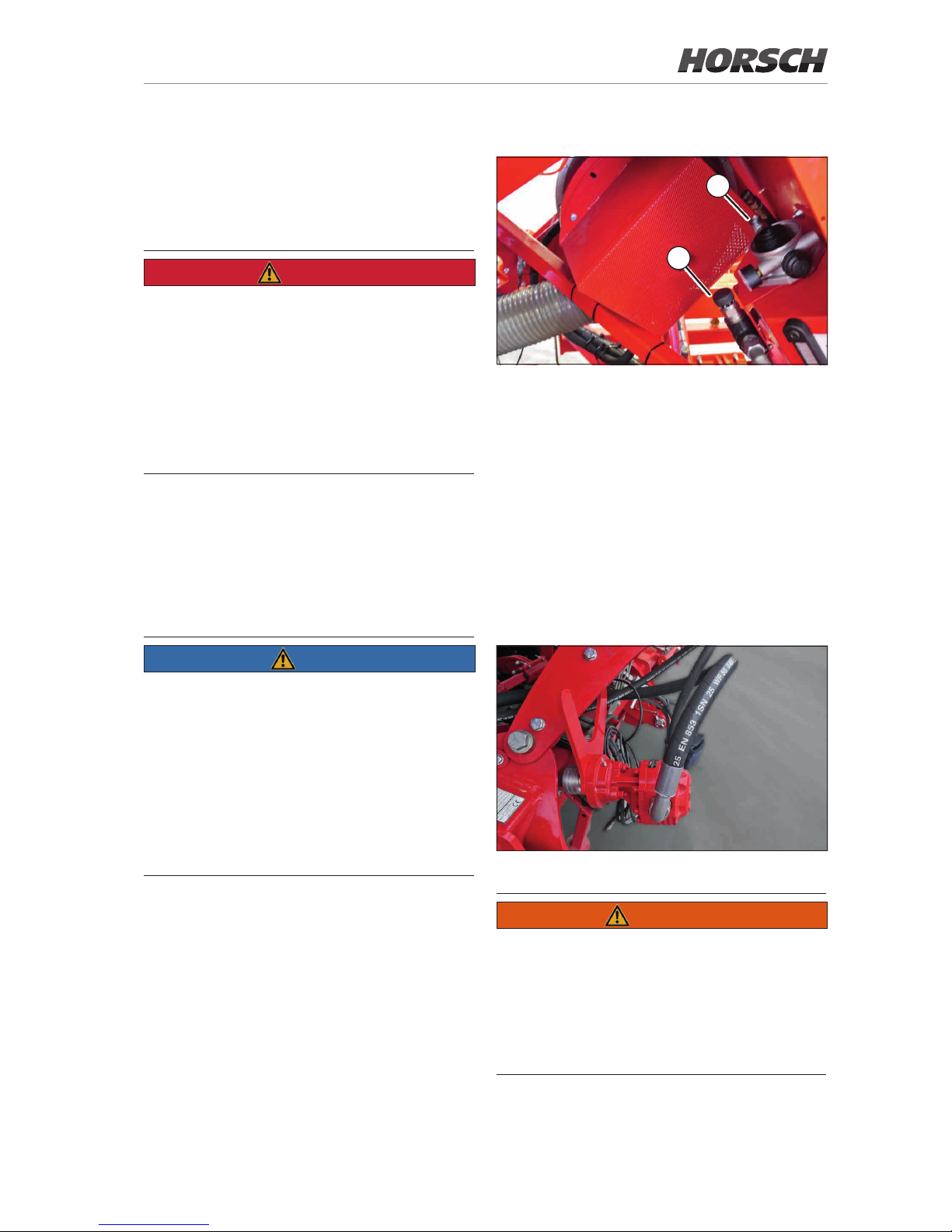
PTO-shaft drive (option)
The fan can alternatively also be driven by a
PTO-shaft pump.
Mounting the PTO-shaft pump
DANGER
Danger of injuring during assembly
¾ Before performing assembly work shut down
the tractor and pull o the ignition key!
¾ Never switch on the PTO-shaft with the en-
gine shut down!
¾ Before switching on the PTO-shaft make sure
that there are no persons in the danger zone
of the machine.
¾ Plug the pump on to the PTO-shaft.
¾ Adapt the universal anti-twist lock to the trac-
tor and fasten securely.
The pump must not move during operation,
otherwise shaft and bearings may be damaged!
NOTE
¾ Before switching on the PTO-shaft make
sure that the chosen PTO-shaft speed of the
tractor complies with the permissible speed
of the device.
¾ max. permissible speed of the PTO-shaft:
1 000 rpm
¾ max. speed of fan: 3 500 rpm
¾ Check all screw connections in regular in-
tervals.
Adjusting the fan speed
2
1
1 Flow control valve
2 Return and vent lter
¾ Select the correct speed of the PTO-shaft on
the tractor.
¾ Set the desired fan speed on the adjustable
ow control valve (1).
Parking position
¾ After parking the machine plug the pump on
the bracket:
PTO-shaft pump in parking position
WARNING
Risk of accident when driving with the PTO-shaft
pump in parking position
¾ Parking position must only be used with the
machine shut down!
¾ For road travel or in the eld the pump should
always be mounted to the tractor!
43
Page 48
Checks and maintenance
WARNING
Risk of injury from running fan
¾ Dismantle the protective grille on the fan only
when the machine is stopped! Operating the
fan without protective grille is not permitted.
¾ Do not expose yourself to the air from the fan
when the pneumatic hoses are disassembled.
NOTE
¾ Fan wing and protective grid must be regularly
checked for dirt deposits and cleaned.
Deposits on the protective grid restrict the air
ow and thus lead to blockage in the seed
pipes.
Deposits on the fan impeller cause unbal-
ance. The bearing will thereby be overloaded
and can be damaged.
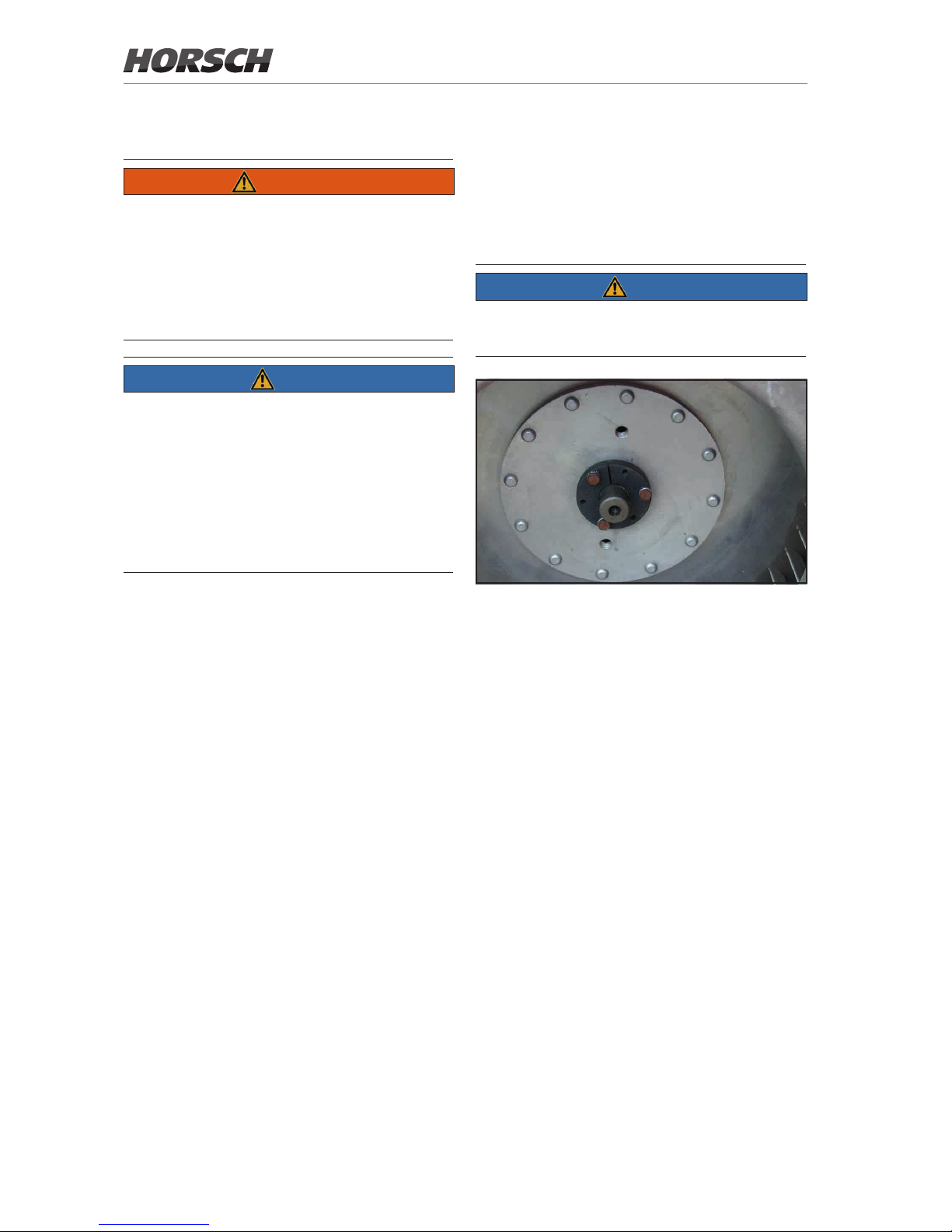
Retightening the fan ange
The clamping taper xates the fan wheel and
additionally clamps on the drive shaft.
The clamping taper on the fan drive may come
loose. The impeller can thus move along the
drive shaft and damage the fan.
NOTE
¾ After approx. 50 hours retighten the clamping
taper on the fan ange and check it annually.
Clamping taper
Please note:
¾ When tightening the screws, especially with
a new assembly, the fan wheel will move
towards the housing in the direction of the
protective grid.
¾ A loose ange must therefore be aligned
closer to the hydraulic motor.
¾ The clamping faces must be free of oil and
grease.
¾ The clamping screws must be tightened uni-
formly and in several steps. Tightening onto
the taper should be supported by light ham-
mer blows on the ange (plastic hammer or
hammer shaft).
¾ The inch screws in design No. 10- 24 4.6
must only be tightened with a torque of
max. 6.8 Nm.
¾ After tightening check the impeller for free and
even running.
44
Page 49
Hopper
1
2
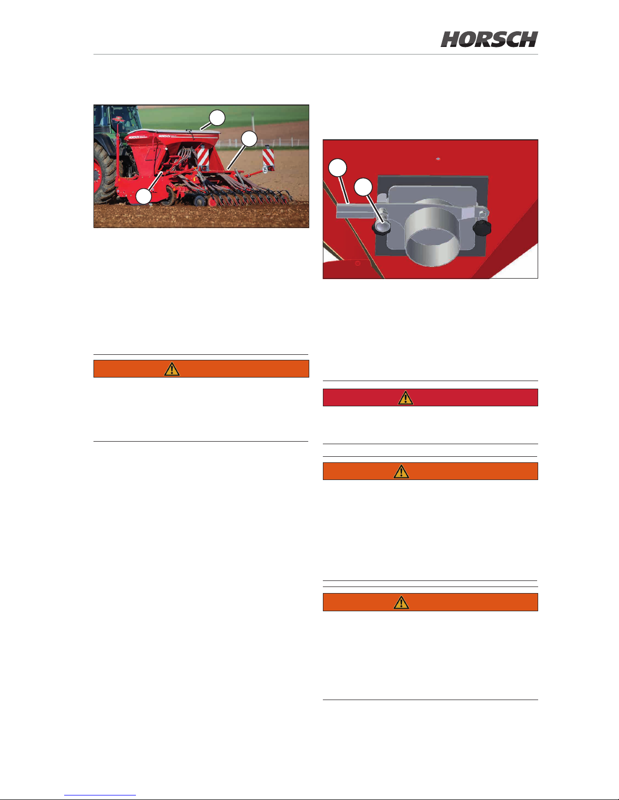
3
Hopper
1 Access steps
2 Platform
3 Covering
Covering
The hopper is closed with a covering.
WARNING
Risk of injury when opening and closing the
covering
¾ Do not let your hand or ngers get caught
between lid and hopper.
¾ Always keep the covering (3) closed to protect
the seed against contamination, dust and
moisture.
In case of extreme development of dust, this
dust can deposit in the hopper and ll up the
roller utes. This causes metering errors and
unnecessary wear inside the metering unit.
Filling
The hopper can be lled from the rear with a
front loader of Big Packs or sacks. The hopper
can be lled from the side with Big Packs.
Discharge gate
A discharge gate is mounted on the side of the
hopper:
5
6
¾ Loosen the interlocking (5).
¾ Pull up the discharge gate (6) to empty the
hopper.
Platform
DANGER
No passengers are allowed to ride on the
machine!
WARNING
Risk of injury on the platform
¾ Move and work carefully on the platform, es-
pecially in the area of the distributor.
¾ Instruct persons to leave the danger zone.
Make sure before movements of the machine
that no persons are about on the platform.
WARNING
Danger of trac accidents caused by access
steps folded down.
¾ Always fold up the access step prior to road
transport.
¾ The interlocking must always engage audibly
and visibly after folding up the access steps.
45
Page 50
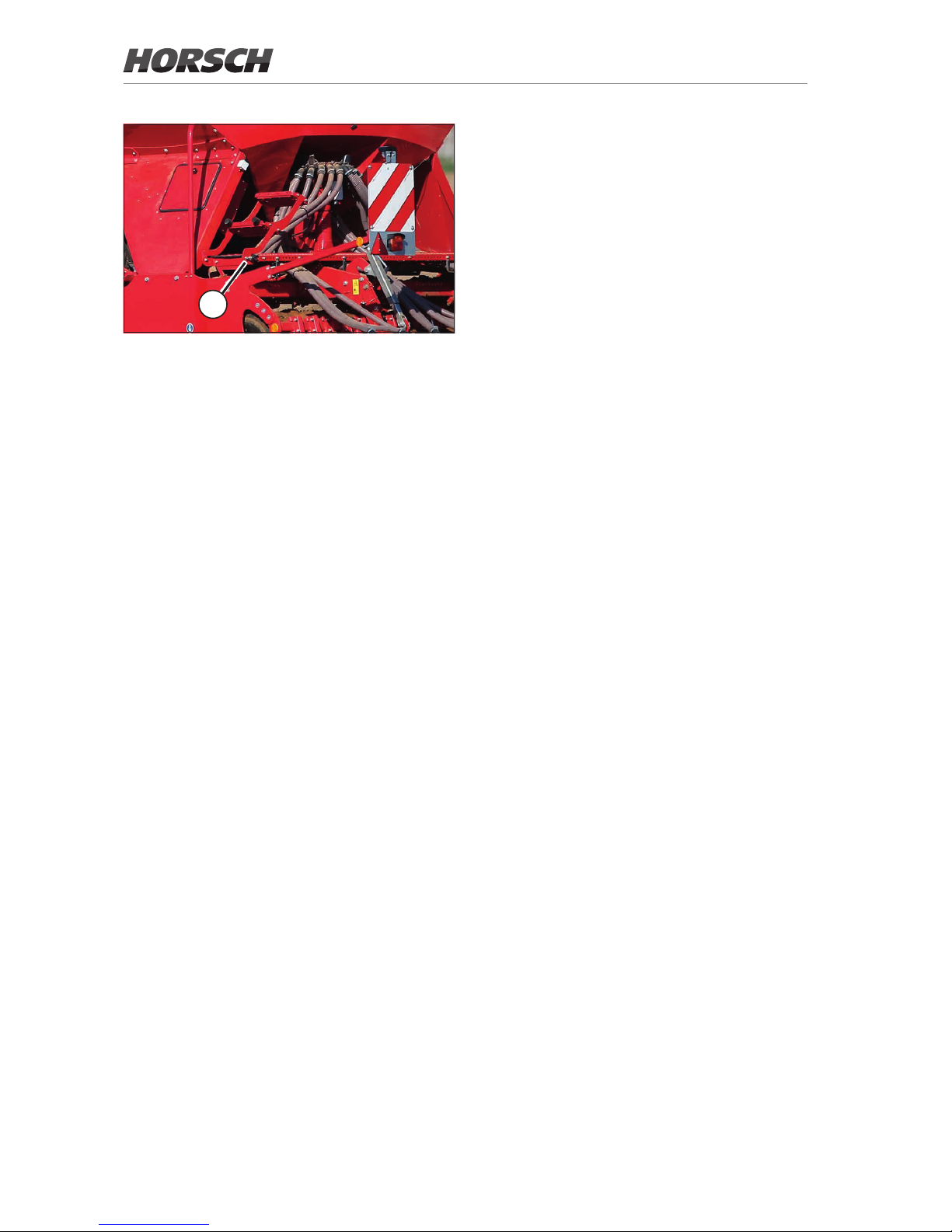
4
¾ Loosen the interlocking (4) to enter the plat-
form and fold down the access steps.
¾ Fold up the access steps and let it engage
after leaving the platform.
46
Page 51
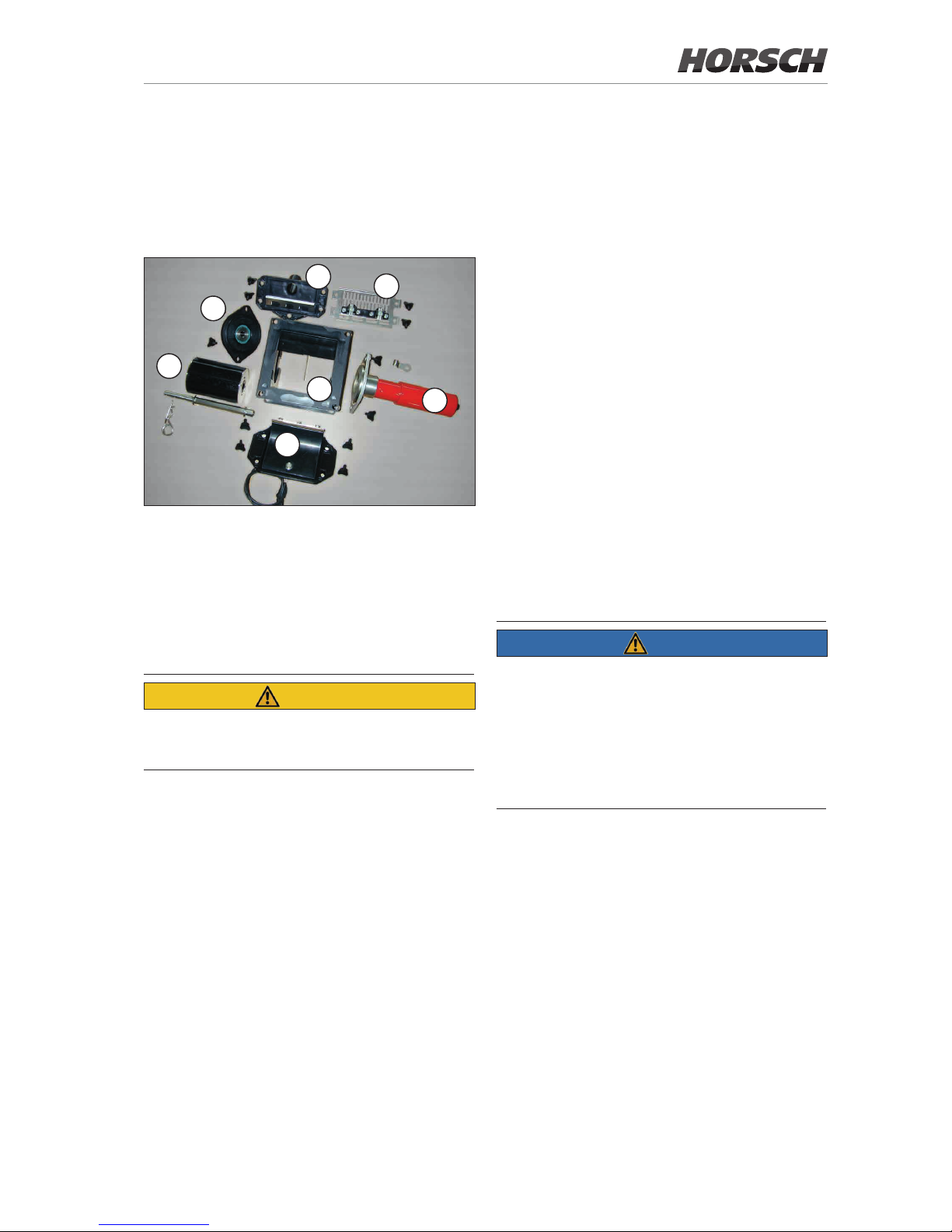
47
Rotors
A large number of rollers is available for the
dierent seed types with numerous geometrical
shapes and grain sizes, as well as fertilisers in
form of powders or granulates.
Rollers with special properties are also available
for fertiliser, ne and coarse seeds.
The selection of individual rollers for various
applications, working widths and delivery
volumes is described in the “E-Manager”
instructions.
The cell rollers are arranged according to their
delivery rate per revolution.
Rollers for double fall sluices
On machines with double fall sluice and two seed
boxes a roller design with symmetric graduation
must be used when using a split roller.
Otherwise the seed is unevenly distributed to
the two halves.
NOTE
Ensure absolute leak tightness of components
with all work activities on the metering unit.
Leaks lead to metering errors.
The contact surfaces must be sealed when
installing the metering unit.
The housing must not be warped when bolting it.
Metering unit
The HORSCH metering unit consists of only
a few individual parts and can be dismantled
without tools.
1
2
3
4
5
6
7
Metering unit
1 Housing
2 Drive motor
3 Clearing valve with sealing lip
4 Roller
5 Side cover with roller bearing
6 Side cover for pressure hopper with scraper plate
7 Side cover for normal hopper with rape brushes
CAUTION
Risk of crushing on the metering unit
¾ Do not reach into the rotating metering unit.
¾ Whenever performing assembly work on the
motor mount it with the bore facing down to
prevent water from entering the housing.
The bottom of the metering unit is completed by
the fall sluice. In the fall sluice the seed is picked
up by the air ow.
During calibration the seed is taken out of the
metering unit through the opening in the fall
sluice.
The covering must subsequently be closed
again tightly.
Page 52
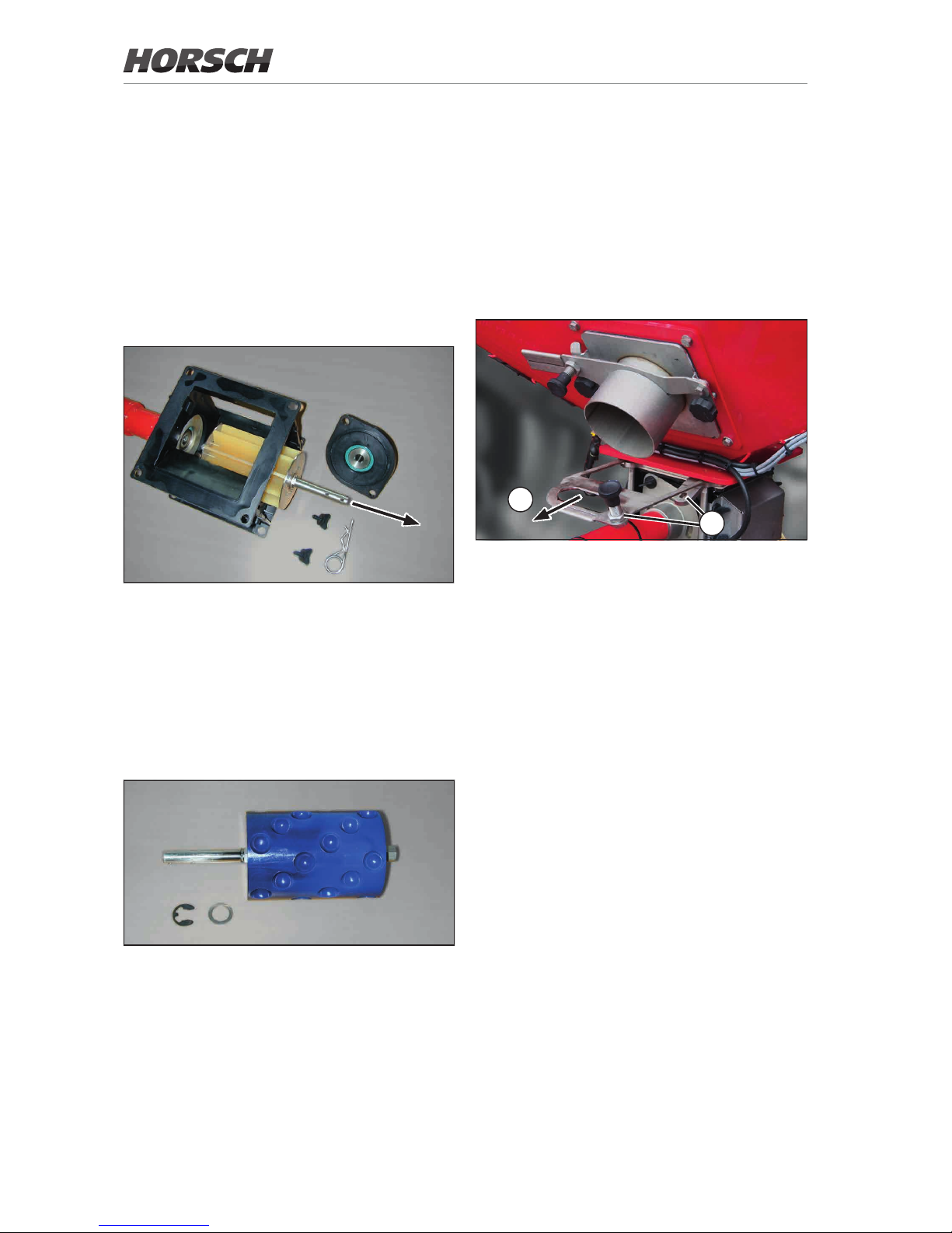
48
Roller change
After choosing a rotor from the table it must be
installed in the metering unit.
¾ Empty the seed hopper, if possible, before
changing the roller.
¾ Unscrew the side cover.
¾ Pull out the roller with the drive shaft.
Rotor change
¾ Remove lock washer and washer.
¾ Pull out the drive shaft and assemble the new
roller.
The drive shaft requires axial clearance in the
roller for self-cleaning of the roller in the metering
housing.
Changing the rotor
The setting of sealing lip and the concentricity
of the roller must be checked after each roller
change.
Roller change with gate
valve
Changing the roller while the hopper is full is
easier if a gate valve is provided above the
metering unit.
¾ Pull out the gate valve (1).
1
2
Gate valve pulled out
¾ Change the roller as described in Roller change.
¾ Push in the gate valve and let it engage (2).
Page 53
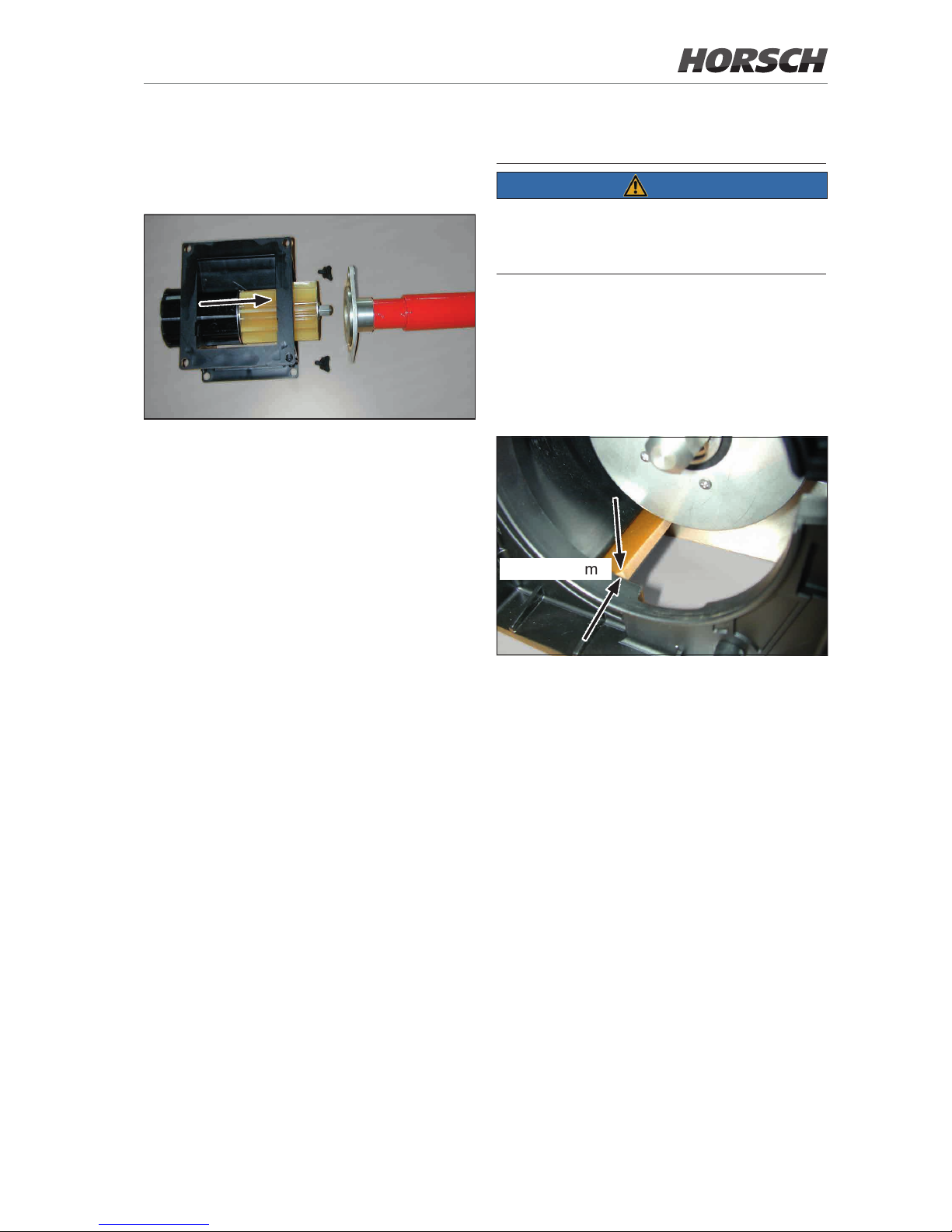
49
Adjusting the sealing lip
NOTE
A defective sealing lip or incorrectly assembled
supporting plate cause metering errors during
sowing.
¾ The sealing lip must not be torn or damaged.
Replace the sealing lip at least 1 x per year.
¾ Insert the side cover with the sealing lip into
the metering housing. The sealing lip must
have full contact with the rotor and should be
able to generate approx. 1 mm pre-tension.
approx. 1 mm
Sealing lip
The retaining plate for the sealing lip is
asymmetrically divided.
With all normal and ne seeds the wider side
must face towards the roller.
In case of faults with coarse seeds such as
maize, beans etc. both the retaining plate and
the sealing lip can be replaced by a wider design.
¾ Take out the roller.
¾ Insert the side cover with the new sealing lip.
Tighten the sealing lip only far enough to still
allow it to slide.
¾ Move the lip so that it projects approx. 1 mm
into the roller recess.
¾ Remove the side cover. Do not move the lip
anymore and tighten it.
¾ Assemble the side cover, check the setting
once again and reinstall the rotor.
Roller change at full hopper
without gate valve
Rotor change with full hopper
¾ Unscrew wing screws on side cover and drive
motor. Remove side cover and motor.
¾ Remove lock washer and washer from the
drive shaft.
¾ Plug the new cell roller on the drive shaft and
use it to push the old roller out of the motor side.
¾ Fix the drive shaft, assemble and fasten side
cover and motor.
Page 54
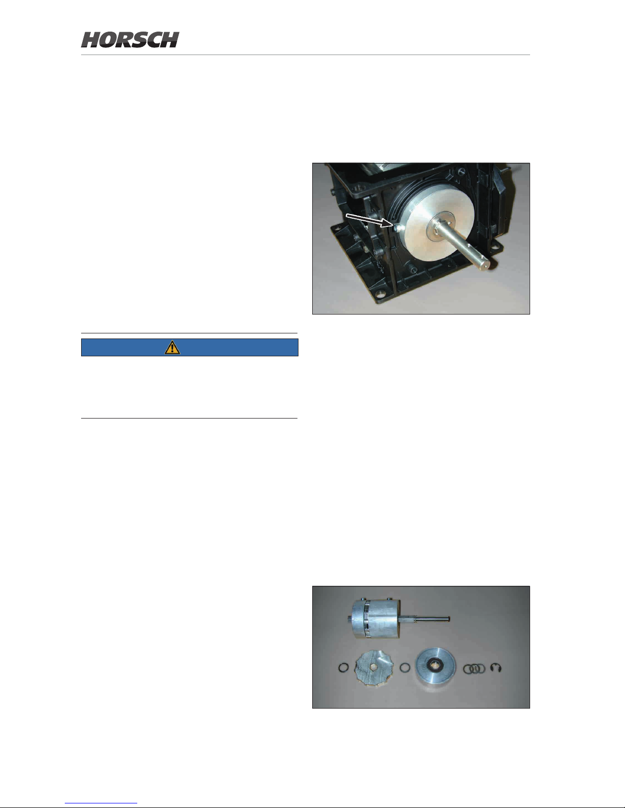
50
Removing or installing a ne seed
roller
The anti-rotation locks must be turned towards
the recess in the housing in order to install and
remove the rollers.
Roller assembly for ne seeds
Maintenance
The function and operability of ne seed rollers
must be checked every day.
¾ There should be no gap between the cell
discs. If the gap is too big, additional shims
must be added.
¾ The cell discs must be light turning. Dressing
or similar materials must not block cell discs
or bearings.
¾ The safety clips must be in place and correctly
assembled to avoid the formation of a gap.
Assembly note
To prevent seed from entering between cell
discs and spacers the cell discs and spacers
are installed with zero clearance shims.
Roller for ne seeds
Rotors for ne seeds
The rollers for ne seeds consist of cell discs,
spacers and drive shaft.
In order to avoid malfunction when sowing
ne seed, the cell rollers are completely pre-
assembled at the factory.
The rollers can be assembled with one or two
cell discs.
The use of two cell discs on the roller doubles
the delivery rate.
Cell discs are available with displacements of
3.5 cm³, 5 cm³, 10 cm³ and 25 cm³.
Only the cell discs in the roller turn while sowing.
The spacers are blocked by stop positions on
the housing.
NOTE
On machines with double fall sluice and 2 seed
boxes you may only use rollers with 2 cell discs.
Otherwise the seed is unevenly distributed to
the two halves.
Page 55
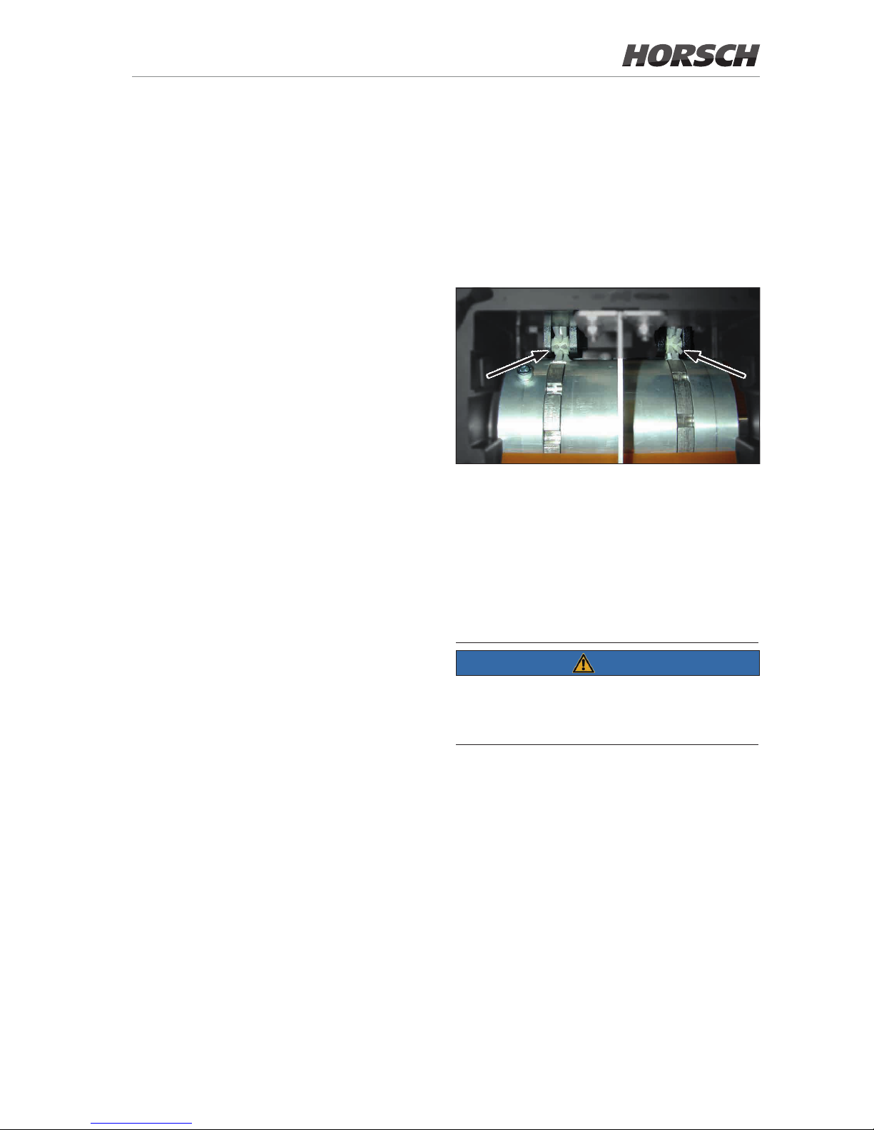
51
The spacers are equipped with bearings.
Depending on the manufacturing tolerance
shims are added to avoid any friction between
cell discs and spacers.
After the assembly of all parts the remaining gap
to the lock washer is lled up with shims.
Finally assemble the lock washer.
With the roller correctly assembled the cell discs
between the spacers can just be freely turned.
The parts must not rub against each other. The
clearance should therefore be as little as possible.
When checking against a light source the gap
should just be visible.
Function test
After installing the new roller the function and
concentricity of the new roller must be checked.
For this purpose switch on the roller as described
in the section “Calibration test”.
¾ The drive motor must run “smoothly”. No sti
points should be recognizable.
¾ Check the motor for smooth running. Untrue
running causes inaccurate metering and may
overload the motor.
¾ Locate any sti points, if possible.
¾ Rework damaged parts (by machining ...) or
replace.
¾ Loosen the screws on the side covers for drive
motor and roller bearing and realign the side
covers to release tension.
¾ If the drive shaft has been bent, realign or
replace it.
¾ Remove any foreign bodies that may have
been jammed between roller and housing.
¾ If dust or dressing in the roller has entered
between cell discs and spacers dismantle
and clean the roller.
Rape brushes
The rape brushes clean the cell discs in the
rollers for ne seeds.
Before sowing ne seeds the rape brushes must
be installed in the side cover and their function
must be checked.
Rape brushes assembled
¾ Check concentricity and fastening.
¾ Check condition and cleaning effect of
brushes.
¾ Install the side cover with the brushes into the
metering unit.
¾ The brushes must rmly rest against the cell
discs and rotate with the roller.
NOTE
The function and cleaning eect of the rape
brushes must be checked before starting sowing
and at regular intervals during work.
Sticking cell discs cause metering errors during
sowing. Less seed is placed.
The side cover with the rape brushes can be
removed even when the seed hopper is full.
Sticking cell discs can then also be cleaned in
assembled condition.
The rape brushes should be disassembled when
sowing normal seeds. The housing holes must
be closed.
Page 56
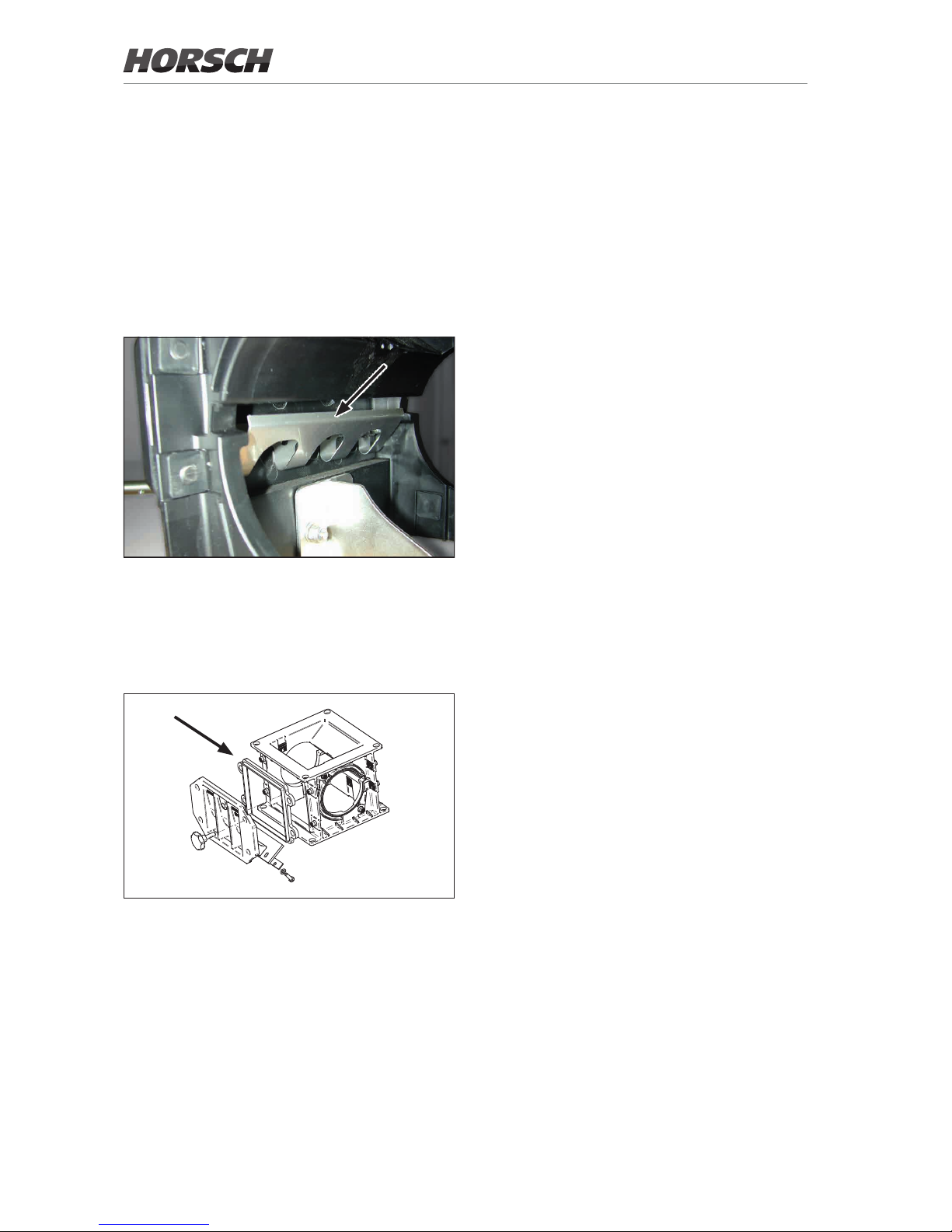
52
¾ If necessary, mix talc or graphite powder with
the seed.
Large seed grains partly have poor trickling
characteristics and thus do not ll the roller
utes completely.
¾ When using the adapter frame you must install
and adjust a wider sealing lip - see adjusting
the sealing lip.
¾ The special rollers for coarse seeds should
be used in this case.
These are available in different sizes to
match the dierent working widths and seed
quantities.
Coarse seeds
For sowing coarse seed (maize, beans, peas,
etc.) the metering unit must be converted.
¾ A deector must be installed instead of the
rape brushes.
This deector prevents large seed grains from
getting caught between roller and housing,
being damaged or blocking the roller.
Deector
¾ For very large grains an adapter frame may
be installed. For large grains this eases the
entry into the metering unit and prevents
grains from being damaged.
Option, see spare parts catalogue
Page 57
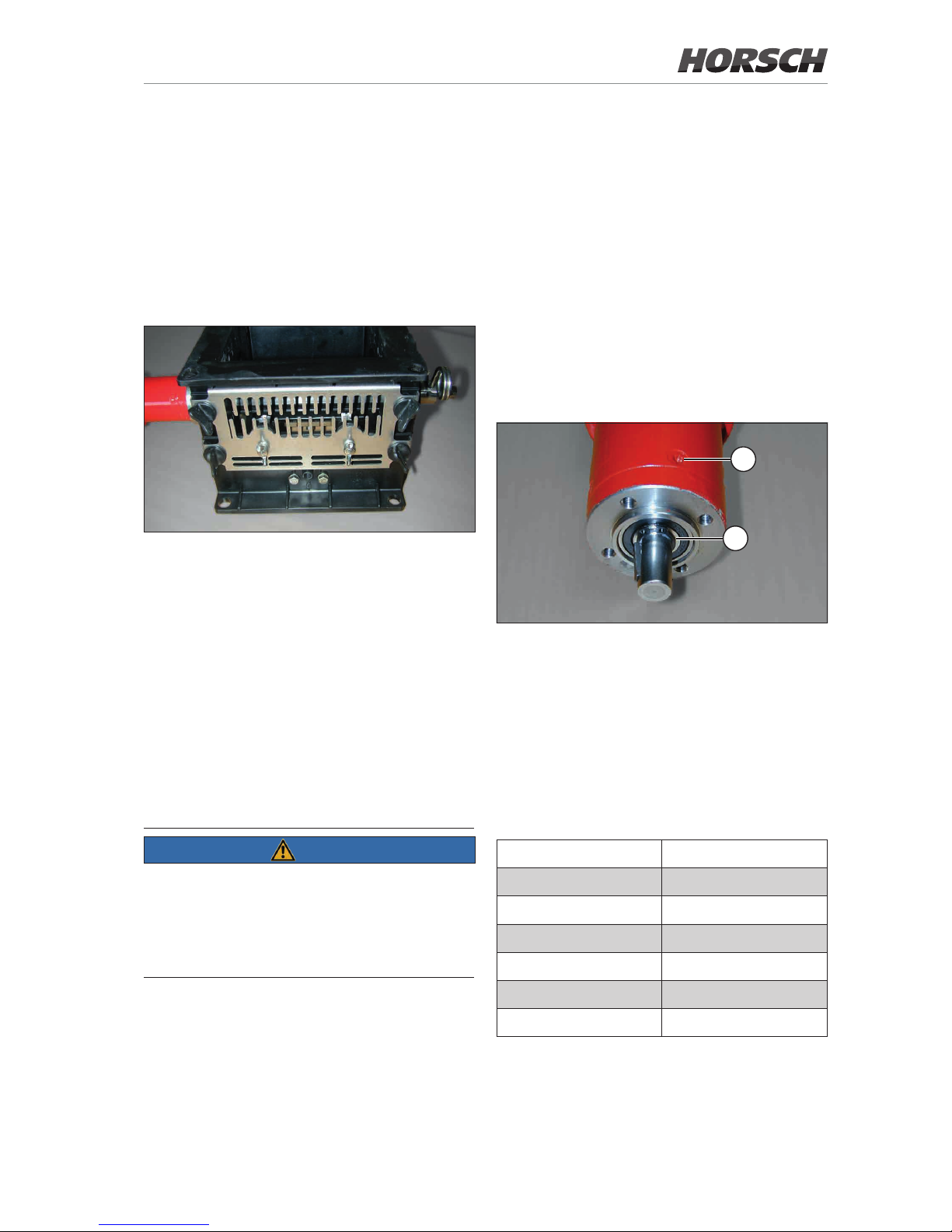
53
Maintenance of the
metering unit
The metering unit does not require any special
maintenance.
In order to avoid repair related downtimes, both
the metering unit and the drive motor should be
cleaned and subjected to a function test after the
end of the season.
The bearings in the side cover in particular
can be damaged or may become hard-moving
because of dressing dust.
If necessary keep bearings in stock and replace
in due time.
2
1
2
Drive motor
1 Screws
1 Radial seal and bearing
Plug assignment on the motor
In case of cable break or repair work on the plug,
the cables can be connected by soldering.
However, the use of crimping contacts is
recommended.
Pin No. Cable
1
blue
2
red
3
white
4
brown
5
green
6
yellow
Metering unit with injector fall
sluice
The metering units in machines with normal
hopper and injector fall sluice are equipped with
a lid (V2A) with machined recesses.
During operation the injector nozzle is exposed
to vacuum. This lid adds additional air to the
air ow.
Metering unit with lid for injector nozzle
The adjustment between injector nozzle and lid
works up to a max. possible seed quantity.
Exceeding this quantity results in a dynamic
pressure at the injector nozzle. This may blow
seed out through the perforated plate, which
leads to a strip-like emerging of the seeds.
These grains are visible on the surface of the
eld before they are covered by the packer or
the harrow.
Under extreme conditions overpressure can
block the seed ow in the hopper. This causes
seed failure.
NOTE
Always check the function of the pneumatic
system and the seed placement but especially
at high placing quantities and working speeds.
No grains should remain on the surface of the
eld.
If grains are blown out, the fan speed needs to
be increased (temporarily up to 4000 rpm)
or the working speed must be reduced until the
injector system works correctly again.
Page 58
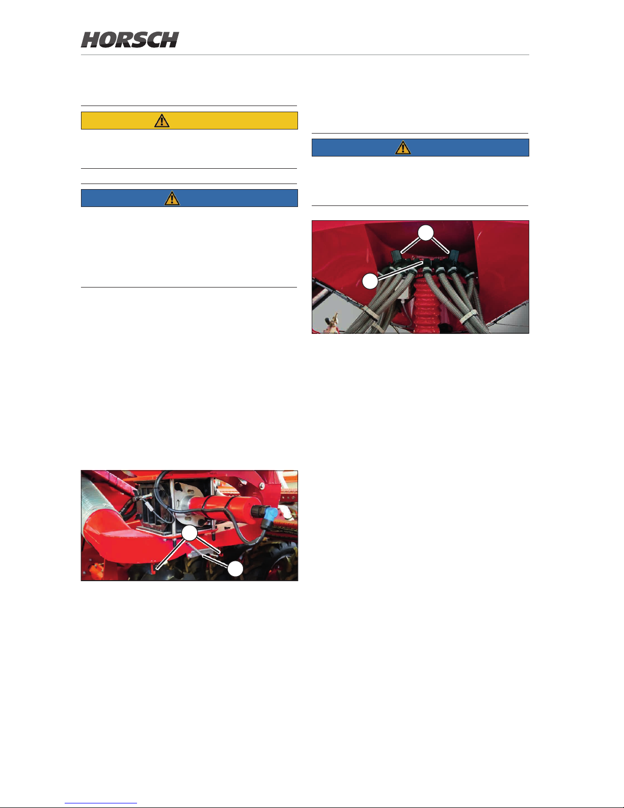
Distributor
A distributor tower is attached to the seed hopper
for seed distribution.
NOTE
All distributor components must be leak tight.
Even slightest leaks and air losses will cause
uneven distribution.
1
2
Distributor tower
1 Seed ow sensors
2 Tram line valves
Valves for tram line control
The distributor is equipped with valves for the
tram line control.
The arrangement depends on the working width,
the tram line rhythm, the track width of the spraying and spreading machine and the number of
valves per track.
The valve function can be checked by examin-
ing the air ow on the seed coulters or the seed
placement on the surface.
The valves have a small identication mark on
the underside of the shaft, which shows the
position of the valves.
This enables checking the rotary motion of the
valve and its end position.
Calibration
CAUTION
Risk of crushing on the metering unit
¾ Do not reach into the rotating metering unit.
NOTE
¾ Calibrate the machine only when lowered and
parked securely.
¾ Do not use sticky dressings with seed. They
inuence metering accuracy.
¾ Check seed and hopper for foreign objects!
¾ Depending on the seed install the rape brush-
es or, for coarse seeds, the adapter frame,
the deector plate and the wide sealing lip.
For grain and fertiliser disassemble the accessory parts. Check all side covers on the
metering unit.
¾ Install the appropriate roller for the seed quan-
tity and check for true running.
¾ Check condition and correct setting of sealing
lip.
¾ Fill the hopper with seed. Only ll in small
amounts of ne seeds.
1
2
¾ Open the valve or covering under the metering
unit (1).
¾ Check and clear the pipes of any dirt and
seed deposits.
¾ Hook the calibration bag on the hook (2).
¾ Calibrate the machine (see E-Manager
instructions).
¾ Close the ap / covering. Ensure air tightness!
54
Page 59
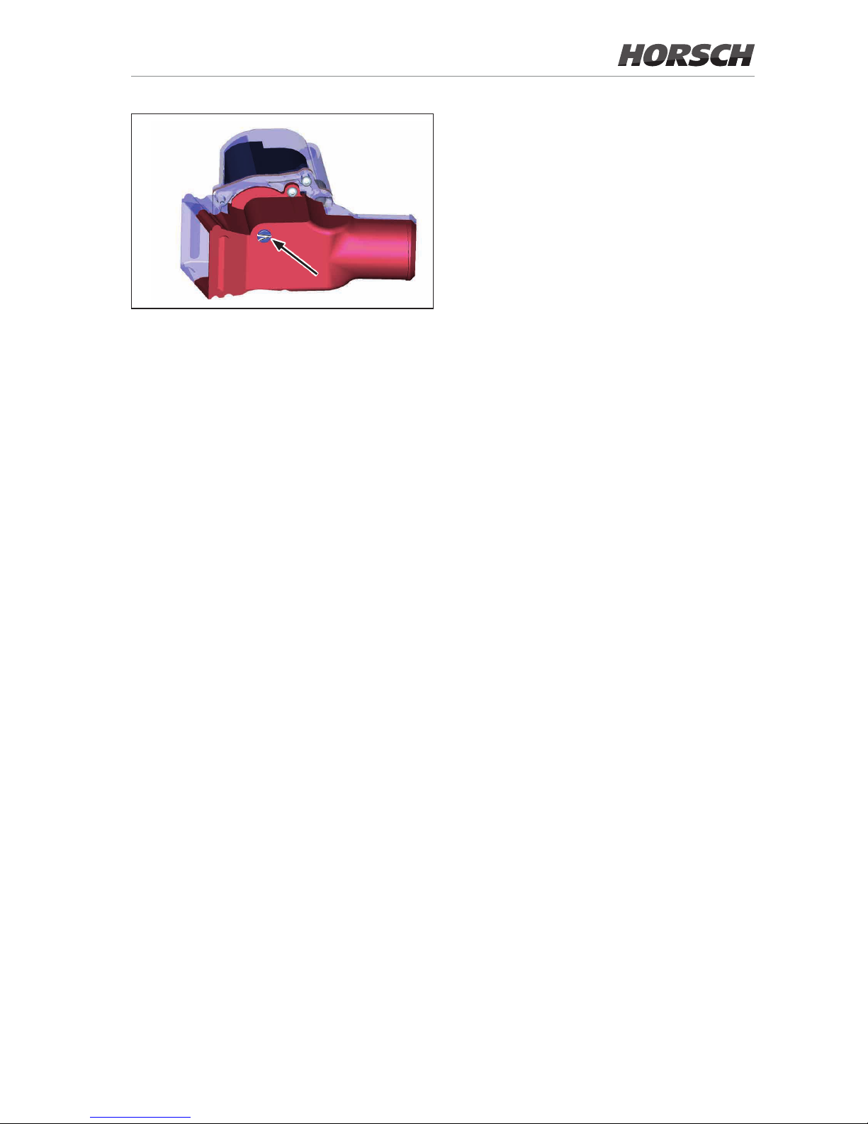
Marking tram line valves (position open)
If the tram line distribution box is equipped with
a track width change-over, the track width must
only be changed when the valves are open.
This can be checked on the terminal (no tram
line must be switched) or by checking the marks
on the valves.
Seed ow monitoring (option)
The seed ow sensors enable the monitoring of
up to 120 seed and fertiliser hoses.
The sensors are connected in series, and the
numbers indicate the order.
In case of an alarm, these sensor numbers help
when troubleshooting the hoses.
If the monitored seed hoses are also tted with
valves for the tram line control, these numbers
must also be entered in a list in the terminal
menu of the tram line rhythms - see E-Manager
instructions.
55
Page 60
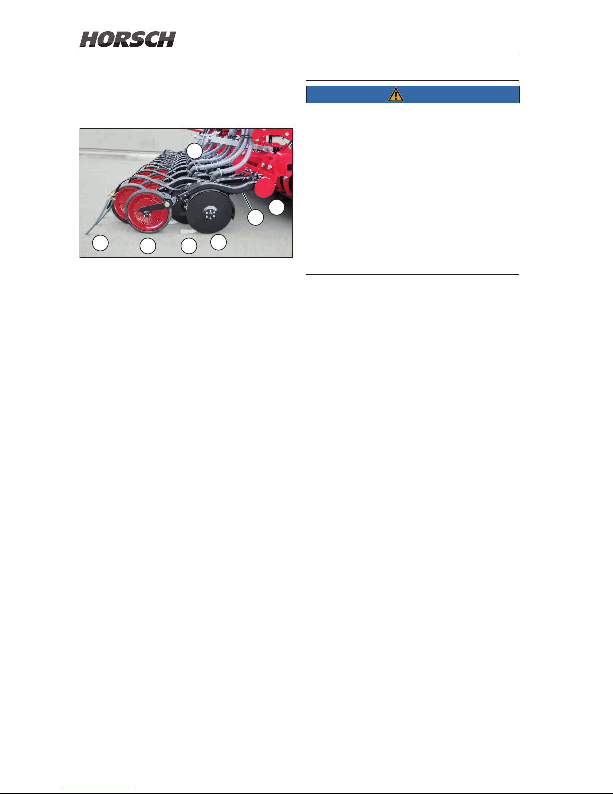
Coulter
Overview
1
2
3
45
6
7
1 Coulter body
2 Rubber bearing for coulter body (maintenance free)
3 Coulter discs
4 Uniformer
5 Press roller
6 Harrow
7 Coulter pressure adjustment (manual)
The seed is placed with the coulters:
• The coulter discs (3) cut through the seedbed
and expose the seed horizon.
• The seed is then placed between the coulter
discs.
• The uniformer (4) holds the seed in the furrow.
• The press roller (5) guides the coulter in depth
and ensures closing of the soil.
• The harrow (6) covers the seed furrow with
soil and calms the ow of soil.
The coulter body is mounted in maintenance-free
rubber bearings (2). It links the coulters and the
press roller and transfers the coulter pressure.
Coulter discs
The coulter discs are arranged at the front at an
angle with slight pretension to each other.
This enables light pulling work and exact opening of the seed channel.
NOTE
• With wet or loose soils the pre-tension of the
coulter discs must not be too high to make
sure that the discs will not block up and wear
unevenly.
• The coulter discs must be slightly preloaded at
the cutting edge. However, turning them easily without extra force must still be possible.
• If one disc rotates, the other one should also
reliably turn as well.
• If the discs stop and block up because of
incorrect preload, too loose soil or wear, the
seed will be placed in bunches.
Wear
This preload will reduce due to wear on the coulter discs or the discs will no longer have contact.
¾ In this case replace the coulter discs and
adjust the preload by removing the washer
again.
Tighten the screws for the coulter disc bearings (socket head cap screw M 16 x 1.5) with
130 - 150 Nm.
Tighten the screws for the coulter discs
(6 x M 8 each) with 38 Nm.
Scraper
The scrapers keep coulter discs and press rollers free of dirt.
¾ Check the function, wear and readjustment
(scraper for coulter discs) of the scrapers at
regular intervals.
56
Page 61
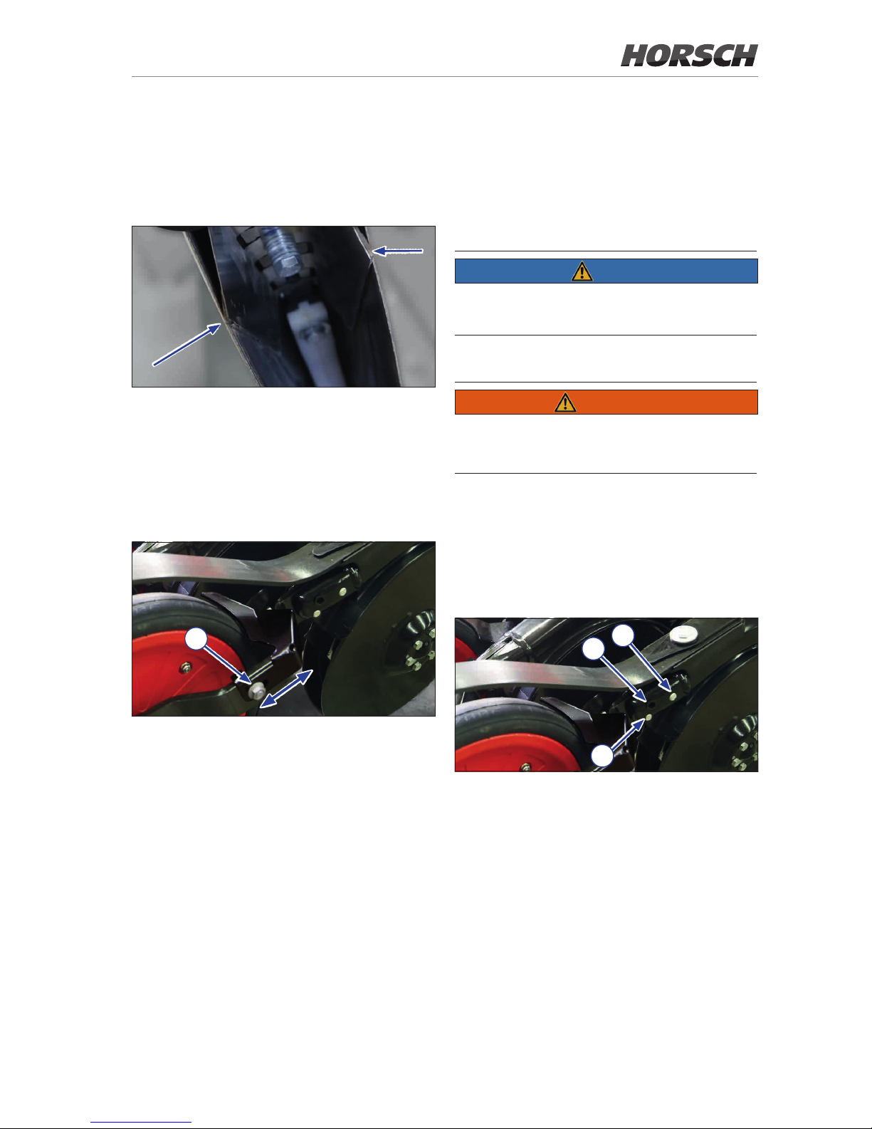
Coulter disc scraper
The scraper features self-adjusting carbide tips
glued to the edges.
¾ Ensure even, slightly angular contact across
the entire range of the coulter disc:
Coulter disc scraper
Press roller scraper
The scraper can be re-adjusted if worn.
¾ Loosen screw (1) to readjust.
¾ Adjust the scraper via the slot.
1
Press roller scraper
¾ Move the scraper as close as possible to-
wards the press roller (approx. 2 mm distance). Rotate the press roller and check for
free rotation during this process. The scraper
should not rub against the (clean) press roller
at any point.
Uniformer
The uniformer rms the seed in the seedbed and
presses it gently down.
Under moist conditions and sticky soils the
uniformer may pick up residues. In this case it
should be removed.
NOTE
¾ To avoid damaging the uniformers do not
reverse with the machine lowered.
Press rollers
WARNING
Danger of injury caused by rotating press rollers
¾ Do not step on the rotating press rollers.
The press rollers guide the depth of the seed
placement, cover the seed with ne soil and
press it down on the seed.
The height of the press rollers can be set to two
positions.
2
3
4
Adjusting the press roller
¾ Loosen the front screw (2).
¾ Remove the plugs (3) and rear screw (4).
¾ Position the press roller and fasten with screw
in the other hole.
¾ Tighten both screws with 100 Nm each and
press in the plugs.
57
Page 62
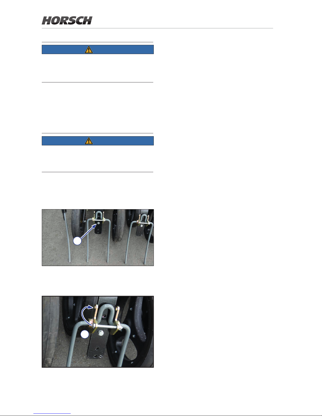
NOTE
¾ Set the press roller to the upper position for
deep seed placement.
This aligns the coulter horizontally.
If depth guidance by the press rollers cannot be
assured on soft and sandy soils, these can be
replaced by press rollers with a width of 7.5 cm
(option).
Rubber mounting
NOTE
¾ Keep the rubber mounting free of oil.
Oils and grease can harm the rubber and thus
adversely aect the function.
Harrow
The height and angle of attack of the harrow can
be adjusted, if necessary.
1
¾ Adjust the height: Unscrew the screw (1) and
tighten the bracket again in the next position.
2
¾ Increase the angle of attack (aggressiveness):
Slightly lift the seed bar and screw down the
screw (2) in the upper position behind the
harrow.
¾ Adjust all harrows equally.
Maintenance
¾ Check press rollers for condition, light move-
ment and tight t.
¾ Readjust the scraper on the press rollers if
required.
¾ Check the scrapers and uniformers for con-
dition, tight t and adjustment.
¾ Check coulter discs and bearings for wear,
light movement and preload.
¾ Tighten the screws for the coulter disc bear-
ings (M 16 x 1.5) with 130 - 150 Nm.
Tighten the screws for the coulter discs
(6 x M 8 each) with 38 Nm.
Check the rubber mounting and replace if aged
or showing reduced tensioning force.
58
Page 63
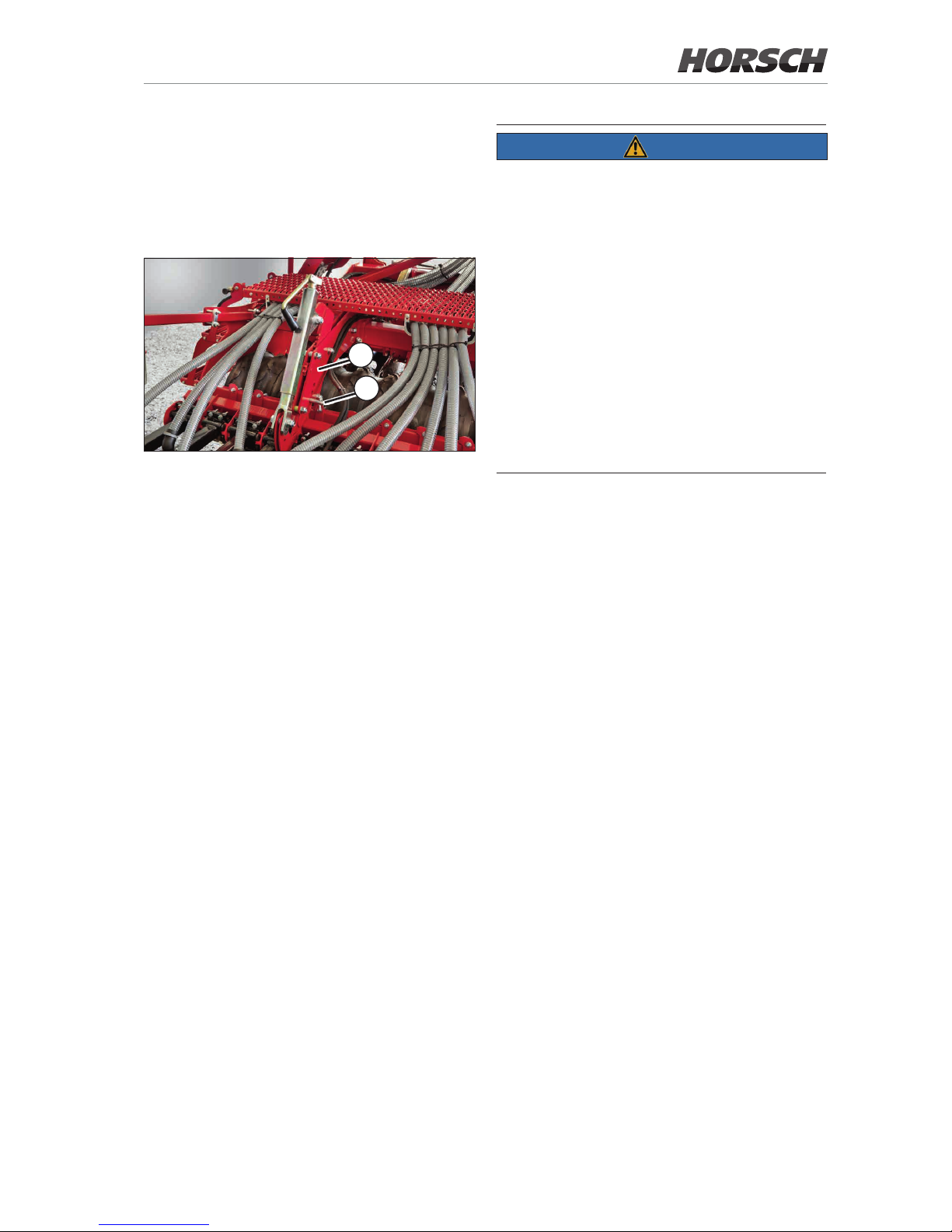
Depth setting
The drilling depth is determined by the depth
setting and the coulter pressure on the coulters.
The drilling depth is adjusted mechanically via
two racks.
1
2
¾ Secure the tractor against rolling away, secure
the control units.
¾ Lower the seed bar until it rests on the ground.
If necessary, vary the height of the seed bar
slightly to facilitate adjustment.
¾ Remove the bolts on both sides (1).
¾ Adjust the height of the seed bar on the racks
using the box spanner (size 24) supplied (2).
Adjust both racks to the same height. Adjust
the height so that the bolts can be inserted.
¾ Insert the bolts at the rows of holes and secure
them with cotter pins.
NOTE
¾ The settings of drilling depth and coulter
pressure aect each other. Check the coulter
pressure in the eld after each change of the
placement depth.
¾ Adapt the adjustment to the soil conditions,
the working speed, harvest residues and the
loosening work of the coulter discs.
It can only be determined in the eld in working position.
¾ With each change, the drilling depth and the
eect of the press rollers on consolidation and
depth guidance must be checked.
¾ Check the drilling depth when starting work
and regularly during use.
Coulter pressure adjustment
When lowering the machine the coulters are
pressed into the soil, until the press rollers take
over the depth guidance.
The rubbers on the guide are thereby tensioned
and the required coulter pressure is generated.
The harder the soil and the deeper the seed is
to be placed, the higher the required pressure.
Adjust the coulter pressure so that the set drilling
depth is reached and the coulters run quietly
during eld work.
Excessive coulter pressure will adversely aect
the placement accuracy of the seed and increases the wear on the coulters.
59
Page 64
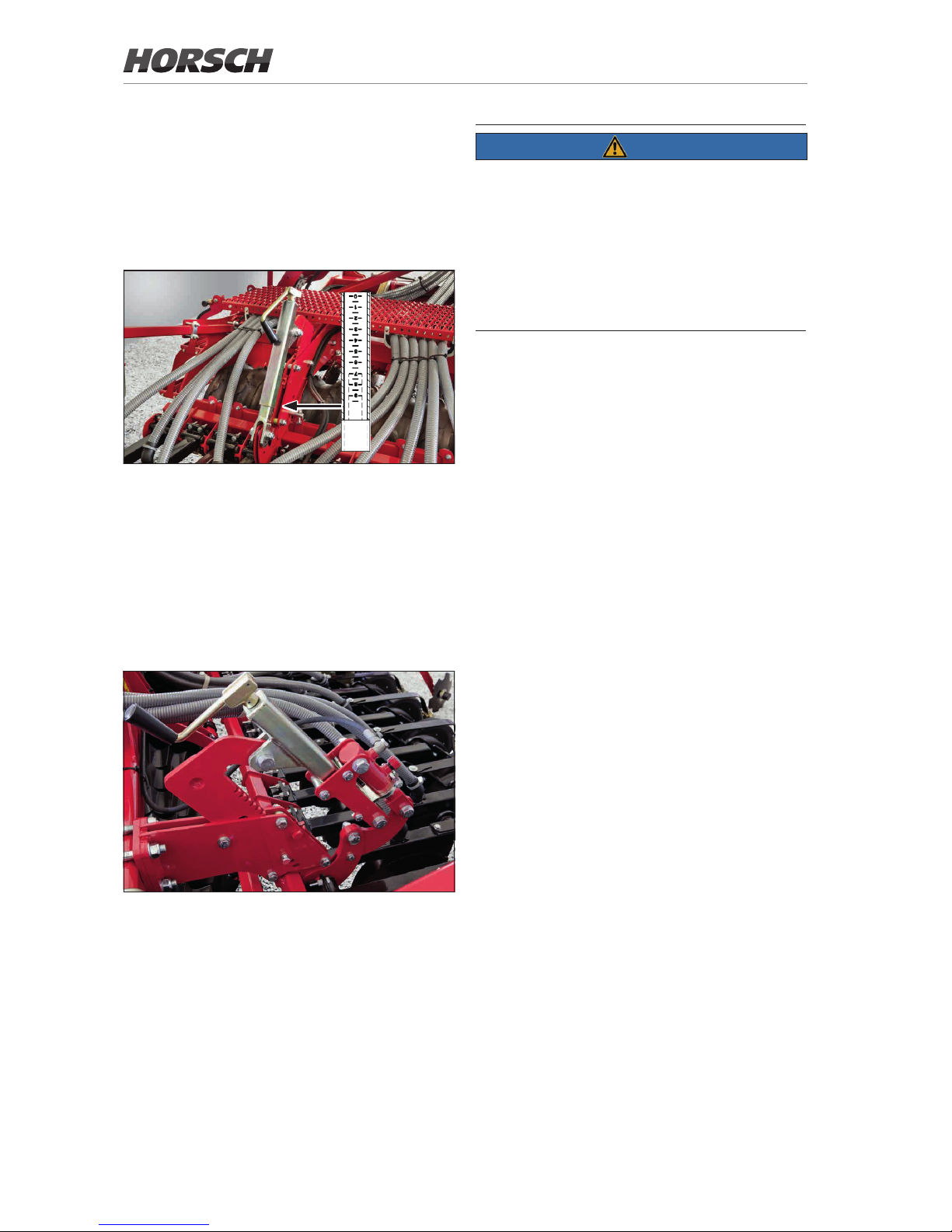
Manual coulter pressure adjustment
The coulter pressure can be increased by backing out the screw adjustment.
¾ Pay attention to the engraved adjusting scale.
¾ Set all screw adjustment uniformly.
Screw adjustment for coulter pressure with adjusting
scale
Hydraulic coulter pressure adjustment
(option)
The hydraulic coulter pressure adjustment allows adapting or increasing the coulter pressure
during changing soil conditions during eld work.
Hydraulic coulter pressure adjustment
¾ To perform the basic setting retract the hy-
draulic cylinders and adjust the coulter pressure with the screw adjustment.
¾ Increase or reduce the coulter pressure
through the hydraulic cylinders according to
the soil conditions.
NOTE
The placing quantity of the seed is increased
automatically with the hydraulic increase of the
coulter pressure.
The placing quantity is reset to the basic setting
or the starting value when the control unit is
switched to oating position.
¾ See operating instructions for the E-Manager.
Interrelationship of coulter pressure and
drilling depth
Changes of the drilling depth mainly eect the
drilling depth, but also the coulter pressure and
the press rollers.
Changes to the coulter pressure adjustment
mainly eect coulters and press rollers, but also
have an inuence on the drilling depth.
¾ Check the coulter pressure after changing the
drilling depth.
¾ Check the drilling depth after changing the
coulter pressure.
If the pressure adjustment is not sucient for the
drilling depth, the seed bar must be lowered by
the rack and the coulter pressure matched again.
Checks
¾ Lower the drill until the packer rests on the
ground.
¾ Drive a few meters with the drill in working
position.
¾ Check seed placement, drilling depth and
consolidation after the press rollers.
¾ If necessary adjust coulter pressure and depth
setting until the correct match is found.
When adjusting the cultivation tools check the
seed placement again
All rods and racks must be uniformly adjusted.
60
Page 65
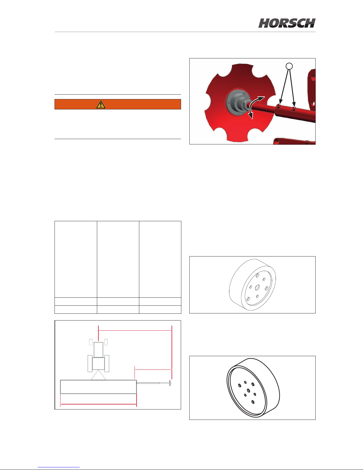
Optional equipment
Bout marker
WARNING
Risk of injury from the bout marker.
¾ Order persons to leave the slewing range of
the bout markers.
When installing for the rst time, the bout markers must be set to working width. Marking takes
place in relation to the centre of the tractor.
The adjustment length of the bout markers
(I, measured from the middle of the outermost
row) results from half the working width (b) plus
half the row distance.
Working width b (cm)
Row spacing (cm)
Length of bout marker I (cm)
3.00 15
157.5
3.50 15
182.5
b
b
l
Adjusting the aggressiveness
a
Bout marker disc adjustment
¾ Adjust the aggressiveness of the bout markers
according to the soil conditions.
¾ To do so, loosen the hexagon screws (a), ad-
just the bout marker disc by turning the oset
rod and retighten the hexagon screws (a).
¾ Check the working pattern of the bout marker
in the eld and correct if required.
Bout marker weights
¾ Mount the bout marker weights on heavy soil
to ensure positive penetration of the discs
into the soil.
Depth limiter
The optional depth limiter can be attached on
very light soils. This prevents the disk from
sinking in.
61
Page 66
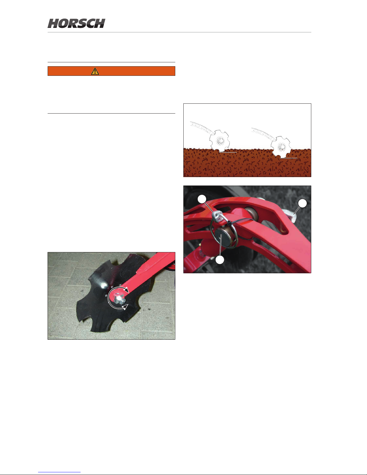
Pre-emergence markers
WARNING
Danger of injury
¾ Make sure before operating the pre-emer-
gence marker that no persons are present in
the danger zone.
The pre-emergence markers mark the tram
lines before the seed grows. They can also be
subsequently mounted to the coulter brackets.
The coulter brackets are hydraulically lifted and
electrically activated by the tram line control
system.
The cutting angle of the coulter discs can be
adjusted to suit the soil conditions and the re-
quested marker depth by rotating the disc angle.
¾ Simply release the bracket and rotate the
four-cornered shaft until the requested coulter
disc angle is attained. Marking should not take
place deeper than necessary.
¾ Then tighten the screws again.
Pre-emergence marker - adapting the marker depth
Depth setting
The pre-emergence markers can be adjusted
in 4 stages:
• Stage 1 - attest position
• Stage 4 - deepest position
1 4
.......
2
1
3
1
2
3
4
Pre-emergence marker set to stage 1.
¾ Loosen the cotter pin (1).
¾ Set the desired stage (3) by turning the han-
dle (2).
¾ Secure with cotter pin.
¾ Set the same stage on both pre-emergence
markers.
¾ Check the marking when starting work and
regularly during work in the eld.
62
Page 67
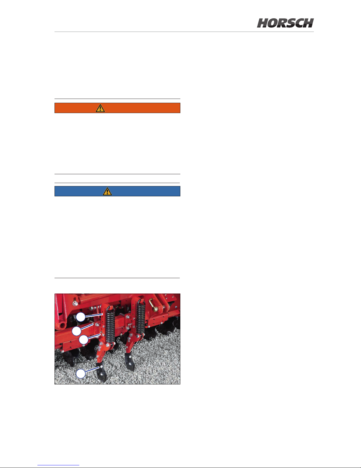
Track loosening tines
By loosening deep tractor tracks the disc system
is able to work in shallower working depths.
The track loosening tines are secured against
overload by means of springs.
WARNING
Risk of injury from stuck tines, which are therefore under tension.
¾ Release the tension from the tines only while
facing away from the spring direction and
using a suitable tool.
¾ Never reach with your hand into a spring
assembly under tension.
NOTE
¾ Make sure that the track loosening tines can
be rmly pressed into the ground when parking without becoming damaged.
However, still park the machine on a rm and
level surface. Point the track loosening tines
upward, if necessary.
¾ The tines must be adjusted to the position
of the respective tractor tyres. Loosen the
clamping screws (1) for adjustment and align
the tines. Tighten the screws on the ange.
3
2
1
4
Track loosening tines
Adjusting the working depth
The working depth must be adjusted to the
respective soil conditions and the tractor used.
¾ Loosen the cotter pin and pull out the bolt (2).
¾ Vertically adjust the track loosening tines via
the row of holes (3).
¾ Insert the bolt and secure it with the cotter pin.
¾ Adjust all tines equally.
Changing tines
¾ Loosen the screw (4).
¾ Insert the new tines in the correct position and
tighten the screws.
63
Page 68

Care and
Maintenance
WARNING
Risk of injuries during maintenance work
¾ Please observe the safety notes on care and
maintenance!
¾ Turn o the tractor and secure it against re-
activation. Lock manual control units in the
locked position.
¾ Secure the machine against lowering and
unexpected movements.
¾ Staying under raised machine parts is pro-
hibited. Secure raised machine parts against
dropping.
¾ Secure machine parts against falling when
dismantling them.
Your machine has been designed and built to
offer maximum performance, economy and
operator friendliness under a vast variety of
operating conditions.
Before delivery the machine was inspected at the
factory and by your dealer to make sure that it is
in optimal condition. For trouble-free operation it
is very important to carry out the necessary work
for care and maintenance at the recommended
intervals.
Cleaning
Clean the machine thoroughly at regular intervals and after the end of the season.
NOTE
Do not clean electrical components and fan or
hydraulic cylinders and bearings with a high
pressure cleaner or direct water jet. Housings,
screw ttings and bearings are not waterproof
under high pressure.
¾ Clean the outside of the machine with water.
Open the fall sluice under the metering unit
so that entered water can ow o.
¾ Clean the cell wheel inside the metering unit
with a brush and compressed air.
¾ Blow out coulters, seed lines, seed hopper,
metering unit and fan with compressed air.
¾ When using fertiliser clean and rinse the
components thoroughly. Fertilisers are highly
aggressive and can cause corrosion.
Lubricating the machine
The machine should be lubricated at regular
intervals and after washing with a pressure
cleaner.
This ensures operability and reduces repair
costs and downtimes.
Hygiene
Lubricants and mineral oil products are no threat
to health as long as they are used as instructed.
Avoid prolonged skin contact or the inhalation
of vapours.
Maintenance intervals
The maintenance intervals are determined by
many dierent factors.
For example, the dierent operating conditions,
weather impact, travel and working speeds, dust
accumulation and type of soil, seed, fertiliser
and dressing used, etc. aect the maintenance
intervals. The quality of the lubricants and cleaning agents also aects the time to the next care
activities.
The specied maintenance intervals therefore
only serve as a reference.
In case of deviations from normal operating
conditions the intervals must be adapted accordingly.
Regular maintenance is the basis for a fully
operable machine. Properly serviced machines
reduce the risk of failing and ensure economical
use and operation of the machines.
64
Page 69

Storage
If the machine is to be shut down for a longer
period of time:
¾ If possible, park the machine under a roof.
¾ Completely empty and clean the seed and
fertiliser hopper.
¾ Reduce the coulter pressure adjustment to
relieve the rubber elements.
¾ Open the clearing valve.
¾ Unplug the terminal and store it in a dry place.
¾ Protect the machine against corrosion. For
spray coating use only biodegradable oils.
¾ Relieve the wheels from any load.
¾ Protect the hydraulic cylinder piston rods
against corrosion.
NOTE
¾ Do not spray the plastic and rubber parts with
oil or corrosion protection agent. These parts
could become brittle and break.
65
Page 70
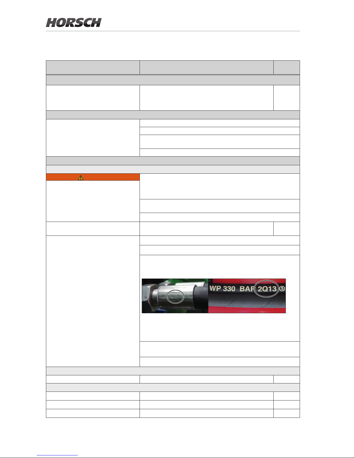
Maintenance overview
Maintenance location Work instructions Interval
After 10 operating hours
Retighten all screw and plug-in
connections as well as the hydraulic
connections.
Even rmly tightened screw connections can come loose (e.g.
because of material settlement or paint residues between the
screw elements). This can lead to loose screw connections
and leaking hydraulic connections.
once
Before the season
Complete machine Read the operating instructions carefully as a refresher.
Check all screw connections for rm seating and retighten as necessary
Check condition and function of all protective features and replace, if
necessary
Check electrical lines for damage and replace, if necessary.
In use
Hydraulics
WARNING
Lower all hydraulically lifted parts (e.g. wings, packer, undercarriage,
etc.) to the ground before performing any work on the hydraulic system.
Depressurise the hydraulics on the tractor and implement side! Empty
the pressure accumulators.
Allow hydraulic oil and hydraulic components heated during operation to
cool down before any work on the hydraulic system.
Observe the notes on hydraulics in the chapter Safety and responsibility.
Hydraulic system and components Check all hydraulic components and hoses for function,
leak tightness, fastening and chang
40 h
Hydraulic hoses
Check the hydraulic hoses regularly for damage (cracks, chang, etc.).
Replace damaged and faulty hoses immediately.
Hydraulic hoses must be replaced after 6 years. For this purpose pay
attention to the manufacturing date on the crimp sleeve (year/month)
and the hose (quarter/year):
Crimp sleeve Hose
Depending on the conditions of use (e.g. weather inuences) or in case
of higher strains on the machine the hoses may need to be replaced
earlier.
Have the hydraulic system checked by an expert at least once every
year.
In addition follow the country specic regulations and directives.
Electrics
Electrical lines Check for damage 40 h
Pneumatic system
Fan, seed hoses and fall sluice Leaks, crushing and chang points, blockage daily
Distributor Check for leak tightness, blockage, clean the distributor daily
Motorised valves Check switching function daily
Express TD
66
Page 71

Maintenance location Work instructions Interval
Fan
Fan Check for leaks, function, speed setting daily
Protective fan grid Clean from contamination
as required
Impeller wheel Check condition and fastening, clean of dirt deposits daily
Tighten the drive ange (rst time 50 hrs) yearly
Leak oil return ow Return ow pressure max. 5 bar daily
Fan with PTO-shaft drive (optional) Check return and vent lter for cleanliness, clean if necessary. 40 h
Change oil and oil lter (workshop work) 1000 h /
annually
before the
season
Metering unit
Rotor and sealing lip Check state, setting and wear - replace the sealing lip at
least once per year.
daily
Rotor Check for sticking cells, clean daily
Motor bearing and housing cover Check for condition and smooth running daily
Rape brush Check condition and function; remove if not in use daily
Coarse seeds Assemble a deector plate daily
Cultivation tools
Rubber mounting Check condition and replace if aged or showing reduced
tensioning force
40 h
Coulter discs Check state, wear, bearing play and light movement. The
discs must be rotatable by hand.
40 h
Coulters and press rollers Check for condition, rm seating and wear daily
Scraper on coulters, press rollers and packer
Check condition, setting and state of wear daily
Bout marker, pre-emergence markers
(option)
Check condition, tight t, function and smooth running daily
Harrow Check condition, tightness, setting and state of wear daily
Screw adjustment Check setting and light movement, lubricate screw daily
Packer shaft Check condition, fastening and smooth running daily
Safety installations
Lighting and warning boards Check condition and function daily
Warning and safety stickers Check that they are in place and legible daily
At the end of the season
Complete machine Perform care and cleaning work; do not spray plastic parts with oil or similar
Spray the piston rods of the hydraulic cylinder with a suitable corrosion
protection agent
Check all screw and plug-and-socket-connections for rm seating (see
torque table)
Check frame and connecting parts for condition and rm seating
Check electrical lines for damage and replace, if necessary.
Store terminal in a dry place
Tractor link arm shaft for wear
NOTES:
• The maintenance interval Daily designates maintenance on each working day before working with the machine.
• Follow additional maintenance notes in the respective chapters.
67
Page 72
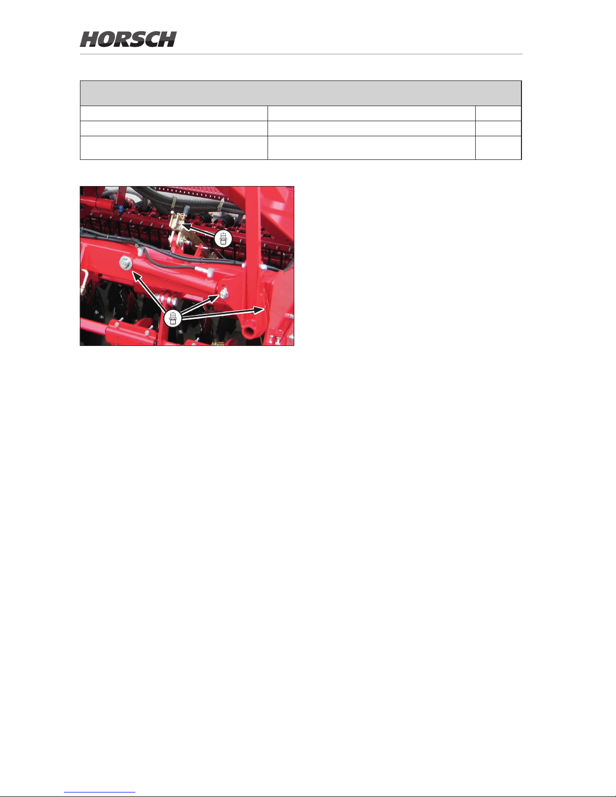
Lubrication points (lubrication grease: DIN 51825 KP/2K-40) - Lubricate the following, number of lubrication
points in brackets
Lubricate bout marker bearings (2x) (1) 40 h
Lubricate hydraulic cylinders bout marker (2x) (2 each) 40 h
Lubricate coulter pressure adjustment crank
and DiscSystem (2x each)
(1 each) yearly
68
Page 73

Waste disposal
Oils, greases and wastes contaminated with
these substances represent a great danger
for the environment and must be disposed of
environmentally and in compliance with the corresponding legal regulations.
If necessary contact your local authorities to get
all relevant information.
Various substances will accumulate during
operation and maintenance, which must be
disposed of appropriately.
For the disposal of auxiliary and operating media as well as other chemicals you must strictly
comply with the specications in the respective
safety data sheets.
Decommissioning
If the machine is no longer suitable for use and
needs to be disposed of, it must be decommissioned. All machine parts must be separated
by material and passed on to environmentally
friendly waste disposal or recycling. Attention
must be paid to all valid regulations.
Decommissioning and waste disposal must
only be carried out by operators who have been
trained by HORSCH.
Contact a waste disposal company, if this should
be necessary.
69
Page 74

Appendix
Tightening torques
NOTE
• The tightening torques only serve as guidelines and are generally valid. Actual data given at the
corresponding points in the operating instructions have priority.
• Screws and nuts must thereby not be treated with lubricant, since this would change the friction value.
Metric screws
Tightening torques - metric screws in Nm
Size
ø mm
Pitch
mm
Screw design - strength classes wheel nuts
4.8 5.8 8.8 10.9 12.9
3 0.50 0.9 1.1 1.8 2.6 3.0
4 0.70 1.6 2.0 3.1 4.5 5.3
5 0.80 3.2 4.0 6.1 8.9 10.4
6 1.00 5.5 6.8 10.4 15.3 17.9
7 1.00 9.3 11.5 17.2 25 30
8 1.25 13.6 16.8 25 37 44
8 1.00 14.5 18 27 40 47
10 1.50 26.6 33 50 73 86
10 1.25 28 35 53 78 91
12 1.75 46 56 86 127 148
12 1.25 50 62 95 139 163
14 2.00 73 90 137 201 235
14 1.50 79 96 150 220 257
16 2.00 113 141 214 314 369
16 1.50 121 150 229 336 393
18 2.50 157 194 306 435 509
18 1.50 178 220 345 491 575 300
20 2.50 222 275 432 615 719
20 1.50 248 307 482 687 804
22 2.50 305 376 502 843 987
22 1.50 337 416 654 932 1090 510
24 3.00 383 474 744 1080 1240
24 2.00 420 519 814 1160 1360
27 3.00 568 703 1000 1570 1840
27 2.00 615 760 1200 1700 1990
30 3.50 772 995 1500 2130 2500
30 2.00 850 1060 1670 2370 2380
70
Page 75

Tightening torques - inch screws in Nm
Screw
diameter
Strength 2 Strength 5 Strength 8
No marks on head 3 marks on head 6 marks on head
Inch mm Coarse
thread
Fine thread Coarse
thread
Fine thread Coarse
thread
Fine thread
1/4 6.4 5.6 6.3 8.6 9.8 12.2 13.5
5/16 7.9 10.8 12.2 17.6 19.0 24.4 27.1
3/8 9.5 20.3 23.0 31.2 35.2 44.7 50.2
7/16 11.1 33.9 36.6 50.2 55.6 70.5 78.6
1/2 12.7 47.5 54.2 77.3 86.8 108.5 122.0
9/16 14.3 67.8 81.3 108.5 122.0 156.0 176.3
5/8 15.9 95.0 108.5 149.1 169.5 216.0 244.0
3/4 19.1 169.5 189.8 271.1 298.3 380.0 427.0
7/8 22.2 176.3 196.6 433.9 474.5 610.0 678.0
1 25.4 257.6 278.0 650.8 718.6 915.2 1017
1 1/8 28.6 359.3 406.8 813.5 908.4 1302 1458
1 1/4 31.8 508.5 562.7 1139 1261 1844 2034
1 3/8 34.9 664.4 759.3 1491 1695 2414 2753
1 1/2 38.1 881.3 989.8 1966 2237 3128 3620
Inch screws
71
Page 76
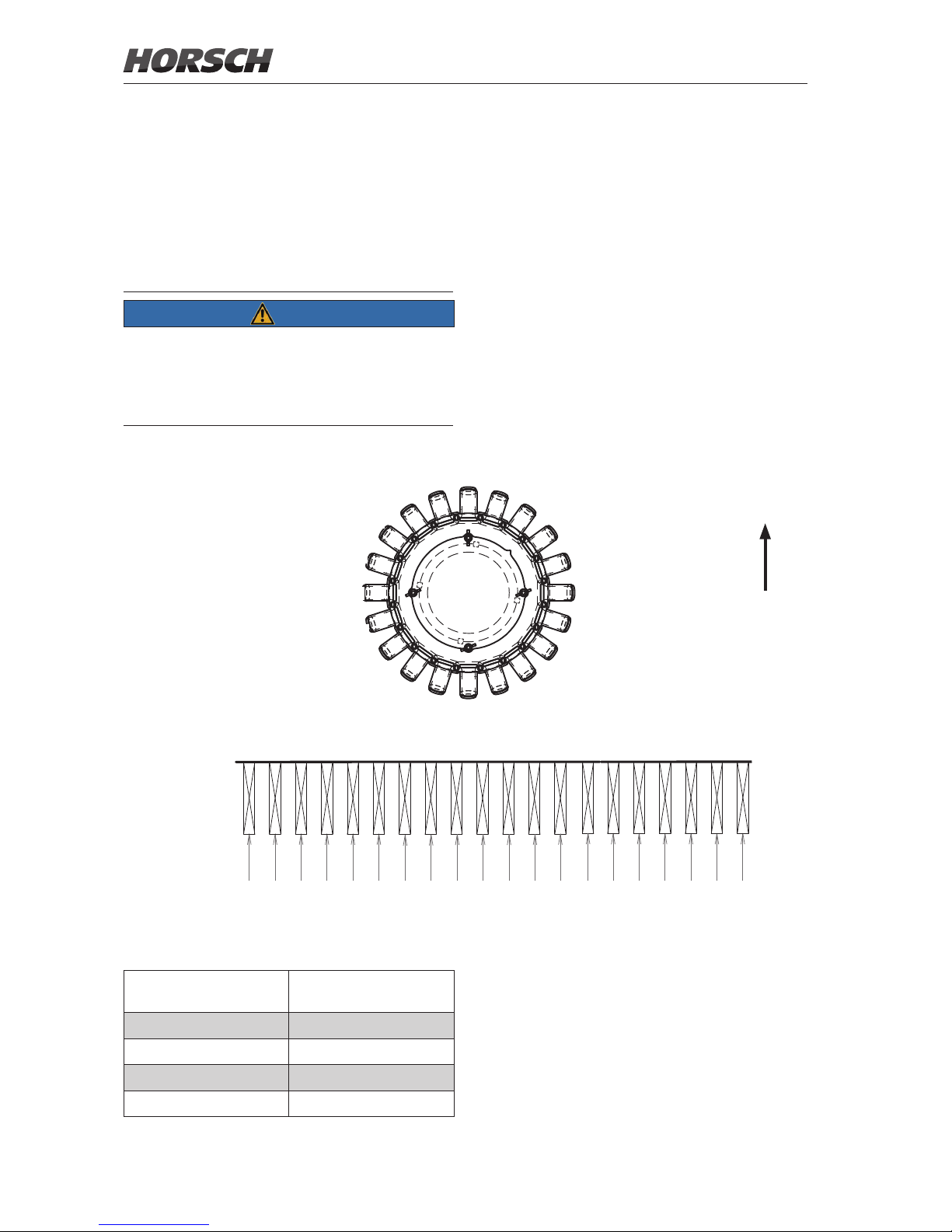
Pneumatics - hose
arrangement
The outows on the distributors are allocated to
the individual outlets on the seed bar through
numbering.
NOTE
Uniform seed placement can only be ensured
when the seed transport to the coulters is
working.
¾ Observe correct hose installation.
Tram line valves
Track width Tram line valves
(Coulter No.)
1.5 m 5, 6, 15, 16
1.8 m 4, 5, 16, 17
2.0 m 3, 4, 17, 18
2.2 m 3, 4, 17, 18
Express 3 TD
Output
Distributor No.
Coulter No.
Direction of travel
Distributor
1
2
3
4
5
6
7
8
9
10
11
12
13
14
15
16
17
18
19
20
1 2 3 4 5 6 7 8 9 10 11 12 13 14 15 16 17 18 19 20
8 2 4 1 39 7 6 5
19 16 15 14 11 12 1318 20 1710
72
Page 77
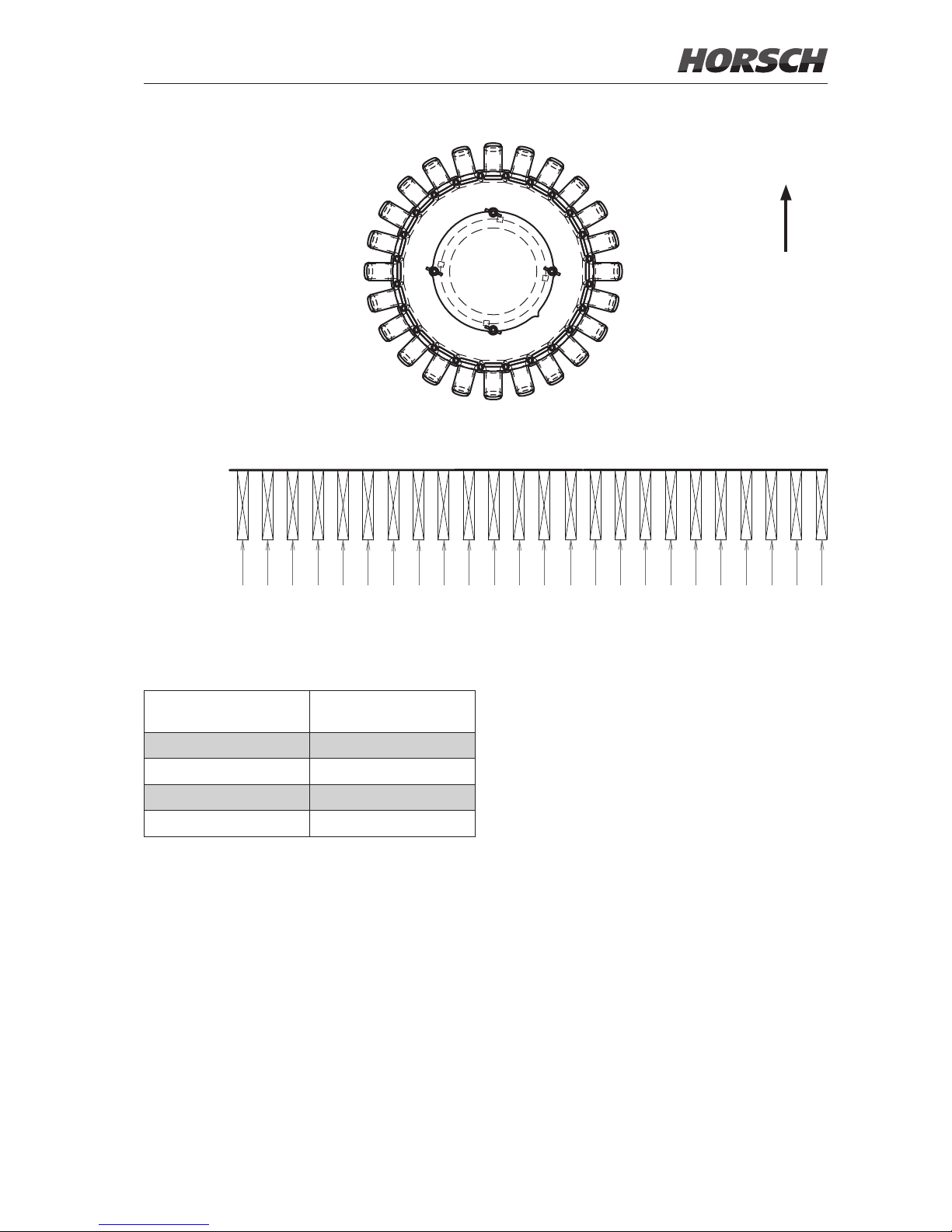
Express 3.5 TD
Output
Distributor
No.
Coulter No.
Direction of travel
Distributor
1
2
3
4
5
6
7
8
9
10
11
12
13
14
15
16
17
18
19
20
21
22
23
24
1 2 3 4 5 6 7 8 9 10 11 12 13 14 15 16 17 18 19 20 21 22 23 24
10 6 3 11 52 9 8 7
13 22 14 19 20 18 17 16 24 23 1512 4 211
Tram line valves
Track width Tram line valves
(Coulter No.)
1.5 m 7, 8, 17, 18
1.8 m 6, 7, 18, 19
2.0 m 5, 6, 19, 20
2.2 m 4, 5, 20, 21
73
Page 78

Index
A
Accessories 6
Adapter frame 52
Assembly 50
B
Bout marker 26,61,67
C
Cable 28
Calibration 54
Care 13
Cell discs 50
Checks 36
Clamping taper 44
Cleaning 64
Clearance 51
Coarse seeds 47,49,52,67
Commissioning 31
Concentricity 51
Connecting 32
Control units 33,35
Coulter 17,56,67
Coulter discs 56,57,67
Coulter pressure 17,59
Coulter pressure adjustment 27
Coupling 10
D
Damage 4
Danger zone 14
Decommissioning 69
Deector 52
Delivery 31
Depth setting 59,62
Direct drive 42
DiscSystem 27,38
Distributor 54,66,72,73
E
Electrics 18
E-Manager 47
Engine power 18
Environment 69
F
Fall sluice 47
Fan 25,37,41
Fan blades 42,44
Fan - fertiliser 67
Fan ange 44
FarmFlex Packer 17,40
Fertiliser metering unit 67
Filling height 17
Flange 44
Foreign objects 51
Foreword 4
G
Gap 50
H
Harrow 58,67
Headland 36
Hopper 45
Hose arrangement 72
Hydraulic coulter pressure adjustment 60
Hydraulics 10,19,24,42,66
I
Impeller wheel 67
Injector nozzle 53
Injector sluice 53
Installation 31
L
Liability 4
Lid 48
Lighting 28,67
Lip 49
Lubrication 64
Lubrication points 68
M
Maintenance 50,53,13,66
Metering error 51
Metering unit 37
74
Page 79

P
Packer 11,40,67
Parking 34
Pin assignment 53
Platform 45
Plug 28
Pneumatic system 37,41,66,72
Pre-emergence markers 26,62,67
Press rollers 17,57,67
Pressure accumulator 10
PTO-shaft 19,43
PTO-shaft drive 43,67
R
Rape brush 67
Rape brushes 51
Recycling 69
Road transportation 8
Roller 47,50
Rotor 67
Rotor change 48,49
Rotors 47
Rubber mounting 58
S
Safety 6
Safety stickers 15,67
Scraper 56,57,67
Screw adjustment 67
Screw connections 13
Sealing lip 48,49,52,67
Seed ow monitoring 55
Seed ow sensors 54
Seed hoses 66
Seed pipe 72,73
Service 5
Shims 50
Side plates 39
Small seed 47,49
Spacers 50
Spare parts 6
Speed 9,41
Stickers 15,29
Storage 65
T
Technical data 17
Top speed 9
Track loosening discs 39
Track loosening tines 63
Tractor 18
Tractor link arm shaft 67
Trac 8
Tram line control 54
Tram line valves 55,72
Transport 31,8
Transport position 33
Transport width 8,17
Type approval 9
Type plate 17
U
Uniformer 57
Use in the eld 11,35
W
Warning boards 67
Warranty 4
Waste disposal 69
Weight 17
Width 17
Wing screws 49
Working speed 17,36
Working width 17
75
Page 80

Page 81

www.horsch.com
All details on technical specifications and pictograms are approximate
and for information only. Subject to technical product revisions.
HORSCH Maschinen GmbH
Sitzenhof 1
92421 Schwandorf
Tel.: +49 94 31 7143-0
Fax: +49 94 31 7143-9200
E-Mail: [email protected]
 Loading...