

Page 1
Operating Instructions
Art.: 80660206 en
Read carefully prior to starting up!
Keep operating instructions in a safe place!
10/2012
DrillManager
Software 8.52
Page 2

Page 3

- Translation of the Original Operating Instructions -
Machine Identication
The corresponding data is to be entered into the list below upon
receiving the machine:
Serial number: .......................................
Machine type: .......................................
Year of construction: .......................................
Initial installation: .......................................
Fittings: .............................................................
..........................................................................
..........................................................................
..........................................................................
Publication date of Operation Manual: 10/2012
Latest change:
Address of Retailer: Name: ......................................................................
Road: ......................................................................
Town/City: ......................................................................
Tel.: ......................................................................
Customer No.:
Retailer: ......................................................................
Address of HORSCH: HORSCH Maschinen GmbH
92421 Schwandorf, Sitzenhof 1
92401 Schwandorf, Postbox 1038
Customer No.:
HORSCH: ......................................................................
80660206 DrillManager en
Page 4

2
Table of contents
DrillManager ..................................................4
Description......................................................4
Wiring loom of machine ................................7
Installing the DrillManager ..............................9
Installation on tractors with
ISOBUS equipment ......................................9
Installation on tractors without
ISOBUS equipment ......................................9
Terminal .......................................................10
Operation ....................................................11
Terminal settings ........................................12
Menu overview .............................................14
Screen display work mask ............................15
Adapting the work screen ...........................15
Function symbols..........................................16
Bout marker and hydraulic control ..............17
Half width shut o .......................................18
Menu overview Calibration .........................20
Seed calibration ............................................21
Rotor selection ............................................24
Seed Check ................................................29
Performance data .......................................29
Input of machine data ................................30
Joining of hoppers ....................................34
Tram line rhythm .........................................39
Seed ow monitoring ...................................52
Entering sensor numbers for FGS ..............52
Setting the sensitivity ..................................53
Seed ow monitoring ..................................53
Alarm message ...........................................54
Seed ow diagnose ....................................54
Diagnostics program.....................................55
Alarm overview ...........................................57
Page 5

3
Page 6
4
DrillManager
The HORSCH DrillManager is an electronic
control unit for drills and their components.
It regulates, monitors and controls all connected
assemblies in the drill.
You should only start up the DrillManager
after you have read the operating
instructions and are familiar with the
operation.
Strict compliance with the applicable accident
prevention instructions and other established
regulations concerning technical and industrial
health and safety is mandatory when working
with the DrillManager.
Description
The HORSCH DrillManager is a complete
system in which the modules included in the
equipment must only be activated.
The complete system consists of the following
components:
¾ Computer
¾ Monitor
¾ Modules, depending on machine type and
equipment, for:
one to three metering drives for seed, fertiliser
or liquid fertiliser
hydraulic control for raising, wings and bout
marker indicator control
half-side control
Seed ow monitoring
¾ Sensors for:
fan
forward speed (radar)
hopper empty indicator (2 channels)
¾ connection for work signal
¾ switch for calibration
All components and sensors are connected to
computer and monitor by means of the wiring
loom.
The computer receives the information, evaluates
these and displays the operating status and data
on the monitor.
If entered or xed default values are exceeded
or fallen short of, or in case of malfunctions the
monitor display is interrupted and the fault is
indicated.
The monitor thereby identies the corresponding
component or the limit value that has been
exceeded.
Depending on the version the machine is
equipped with one or two computers.
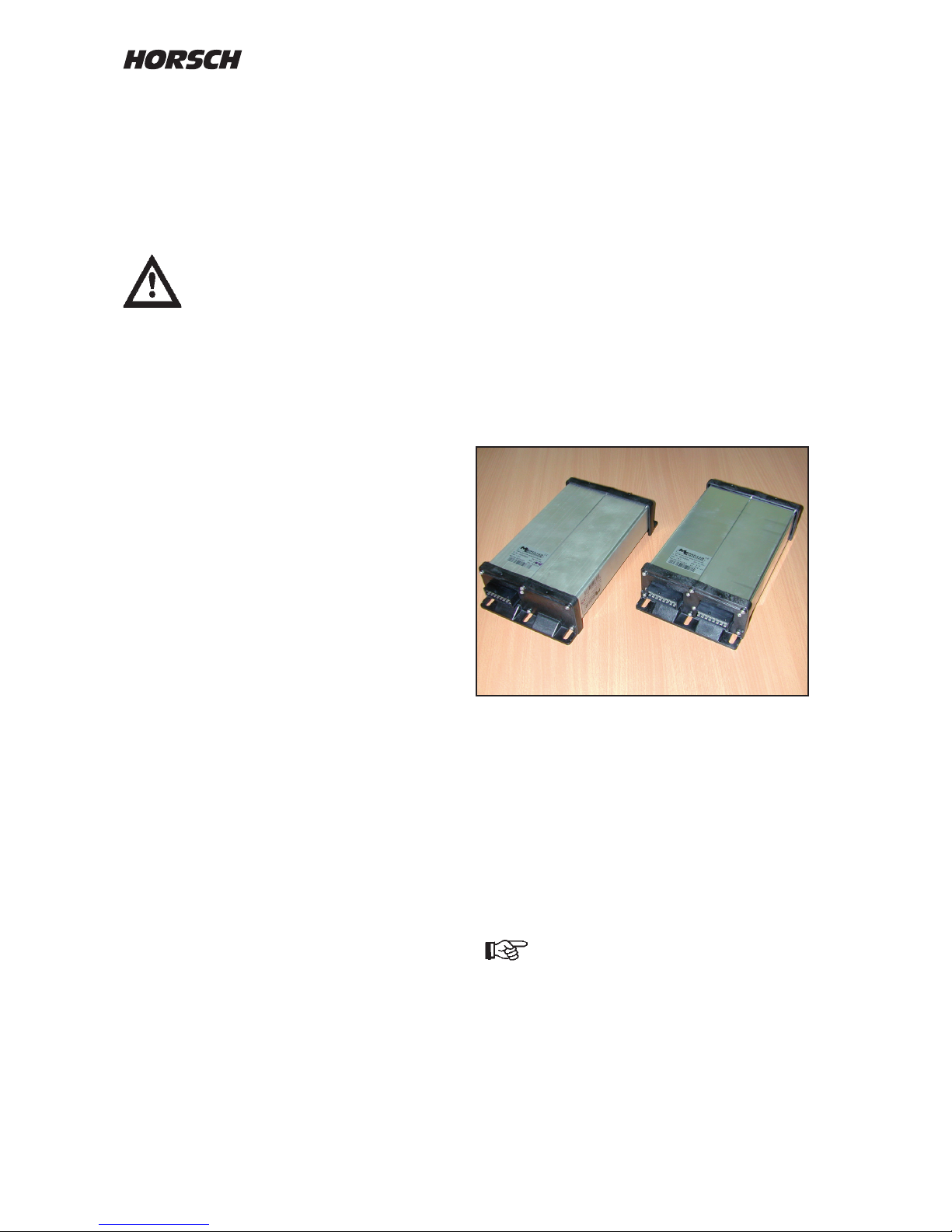
Computer with one and two 16-pin plugs
Stickers on the computer inform about the
hardwar status, the software status is displayed
in the “Diagnose” menu.
Maintenance
The system is maintenance free. You should
keep an eye on the computer and the cable
connections when washing the machine.
Do not clean the computer, the plugs
and any of the electronic components
with high pressure cleaning equipment
or a direct water jet.
Page 7

5
Description of the computer
Computers with black plastic end plates have
program “version 8.xx” installed.
These computers can be operated with HORSCH
terminals, external ISOBUS terminals and with
ISOBUS compatible tractor terminals.
Machines with two computers
On machines with two metering drives two
computers are installed in the machine and
tightly connected together with a cable.
On drills which are temporarily combined with
an additional metering drive, like DuoDrill or
Maistro, the computers of both machines are
connected with a 16-pin plug.
The socket of this connection has an integrated
ISO-Bus termination and can thus can only be
replaced by an original cable in case of a repair.
Computer version
The computer is available in three dierent
hardware versions, whereby two of these
versions look optically exactly the same. It is
therefore very important to look for the article
numbers when carrying out repair work.
No. 00345005 (standard computer)
¾ Installed in all machines with just one
computer;
¾ Is able to control two metering drives;
¾ Is always programmed with the master
version 8.xx 49;
¾ Cable inlet: One 16-pin plug;
No. 00345069 (dual computer)
¾ Installed as master computer in all machines
with two computers;
¾ In connection with the second computer this
computer is able to control three metering
drives or two metering drives and the Maistro;
¾ Is always programmed with the master
version 8.xx 49;
¾ Cable inlet: Two 16-pin plugs;
No. 00345091 (additional computer)
¾ Is used a second computer in machines with
two computers
¾ Supports the main computer in the control of
the third metering drive
¾ Is always programmed with the slave version
8.xx 4a;
¾ Cable inlet: One 16-pin plug
Programs
The programs can be identied by their ending,
e.g. 8.xx 49 for the master version and 8.xx 4a
in the slave version. This ending can only be
recognized during programming.
On machines with dual computers the new and
old computer versions must not be combined.
When replacing an old computer it may be
necessary to replace both computers.
The programs in both computers must also be of
the same version, e.g. 8.52 49 only with 8.52 4a.
In case of incorrectly combined program
versions errors and malfunctions may
occur.
Page 8
6
Pin
No.
Colour Function Colour
/ No. of
part
37 bl/rd Radar signal gn
38 br/wh Rotary speed 2 (right)
Metering unit 2 lling level
sensor
gn
39 gn/wh Fan signal gn
40 rd/ye Hopper 1 lling level sensor gn
41 bk/ye Metering unit 1 lling level
sensor
gn
42 bl Ground 0 V power
Ring ye Shielding (motor) ye 6
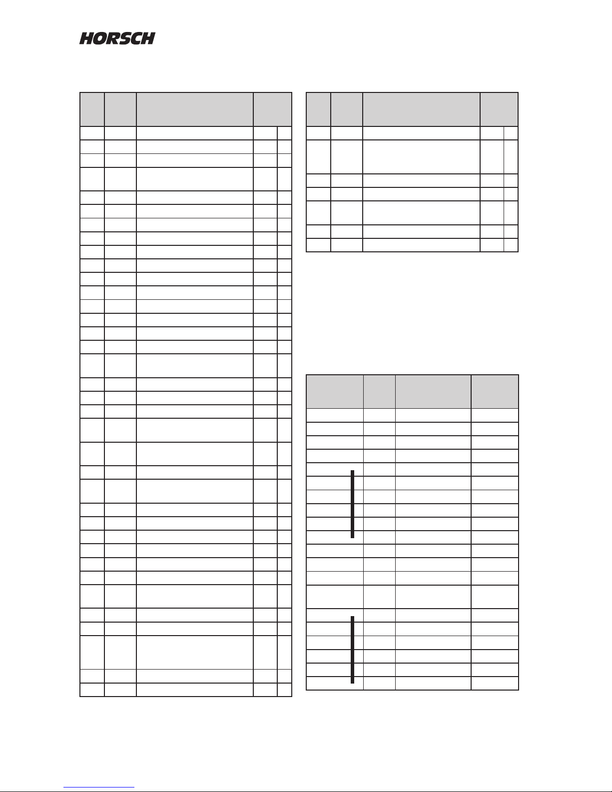
Cable assignment on on connecting cable
20 and 16 pin plug
Plug
20 pin on
tractor
Cable
No.
Function Plug
16 pin on
Computer
A 1 1 1
A 2 2 Can Low 2
A 3 3 Can GND 3
A 4 4 0 Volt electronics 4
A 5 5 0 Volt power 5
A 6 6 0 Volt power 6
A 7 7 0 Volt power 7
A 8 8 0 Volt power 8
A 9
A 10
B 1 9 9
B 2 10 Can High 10
B 3 11 Can EN 11
B 4 12 12 Volt
electronics
12
B 5 13 12 Volt power 13
B 6 14 12 Volt power 14
B 7 15 12 Volt power 15
B 8 16 12 Volt power 16
B 9
B 10
Cable assignment on the 42 pin plug
Pin
No.
Colour Function Colour
/ No. of
part
1 gr Motor 2 plus 12 V power rd
2 gn Half width signal right 3
3 ye Half width signal left 4
4 gr Rotary speed 1 (left)
Hopper 2 lling level sensor
gn
5 pu Hydr. boutmarker left 1
6 rd Hydr. boutmarker right 2
7 bk Tram line +/- right 1
8 vi Tram line -/+ right 2
9 or Tram line +/- left 3
10 br/gn Tram line -/+ left 4
11 wh/rd Pre-emergence marker right 5
12 gn/bl Pre-emergence marker left 6
13 - - -
14 - - -
15 gn Motor 1 minus power bl 1
16 rd/bl Work position signal br
17 ye/bk Motor 1 current
measurement
18 wh/bk Half width signal middle gn
19 rd/bk Hydr. "Lift" 3
20 br/ye Hydr. "Wings" and horn 4
21 rd/wh Liquid fertiliser ball valve +/-
Fan control +/-
br
22 rd/gn Liquid fertiliser ball valve -/+
Fan control -/+
bl
23 - - -
24 br/bk Liquid fertiliser solenoid
valve
25 bl/ye Half width motor +/- 1
26 bl/gn Half width motor -/+ 2
27 - - -
28 br Motor 2 minus power bl
29 rd Motor 1 plus 12 V power rd 2
30 gr/rd Calibration switch signal br
31 gn/gr Motor 2 current
measurement
32 br Sensors all 12 V plus br 4
33 wt Sensors all 0 V electr. wt 3
34 gn/pk Liquid fertiliser. Sensor /
signal coulter pressure
adjustment
gn
35 ye/bl Motor 2 signal gn
36 gn/bk Motor 1 signal gn 5
Page 9
7
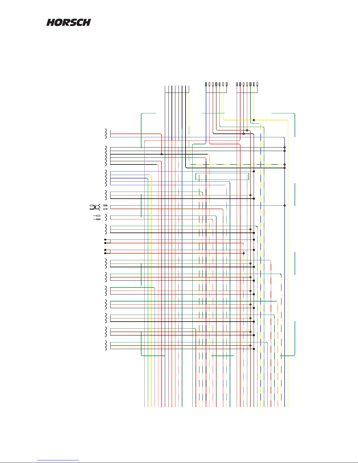
Wiring loom of machine
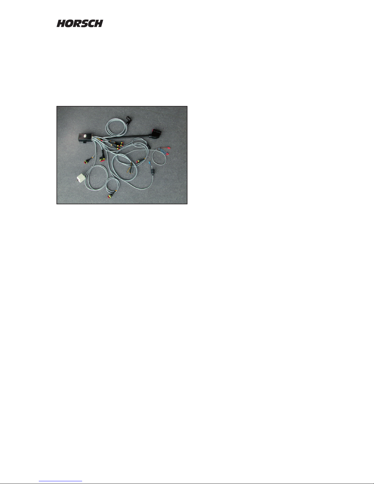
The wiring loom is adapted to match the
corresponding machine type and prefabricated
with plugs for all equipment variants.
In order to avoid malfunctions caused by dirt,
all open plugs must be closed with blind caps
or similar.
Wiring loom
Pin assignment in all 3 pin plugs
1 - ground cable, white
2 + plus cable, brown
3 signal cable, green
Plug designations:
A Work signal
B1 Bridging metering unit 1
B2 Bridging metering unit 2
D1 Speed monitoring, shaft 1
D2 Speed monitoring, shaft 2
G Fan
H Horn
R Radar - speed
S Signal middle position of half width
SV Coulter pressure adjustment
T1 Filling level monitoring seed hopper 1
T2 Filling level monitoring seed hopper 2
K Ball valve (liquid fertiliser)
D Flow sensor (liquid fertiliser)
2 pole at plug with diode - shut-o valve
Cable 8 pole automatic tram line control set
to "Magnet".
1 + Valves right
2 + Valves right
3 + valves left
4 + valves left
5 + Pre emergence markers right
6 + Pre-emergence markers left
7 - Ground all
8 - Ground all
Cable 8 pole automatic tram line control set
to "Motor".
1 + / - Motor right
2 - / + Motor right
3 + / - Motor left
4 - / + Motor left
5 + Pre emergence markers right
6 + Pre-emergence markers left
7 - Ground
8 - Ground
6 pole hydraulic control, "Lift", "Wings" and
"Bout marker".
1 + Bout marker left
2 + Bout marker right
3 + Lifting / lowering
4 + Wings
5 - Ground all
6 - Ground all
5-pin half width control
1 Adjustment motor + / 2 Adjustment motor - / +
3 Signal right
4 Signal left
5 Signal output
7-pin Motor metering drive
1 - blue
2 + red
3 white
4 brown
5 green
6 yellow
Page 10
8
ed jul 11
DatumEntw.DateinameZeichnungsnummerMaschine Zeichnung
-
+
sig
1234567
Motor -
Motor +
Sensor -
Sensor +
Sensor Signal
Abschirmung
-
+
sig
1234567
Motor -
Motor +
Sensor -
Sensor +
Sensor Signal
Abschirmung
124567gn/ge
Motor rechts +/-
Motor rechts -/+
Motor links +/-
Motor links -/+
Vorauflaufmarkierer rechts +
Vorauflaufmarkierer links +
Masse für 5 und 6
Masse für 5 und 6
3
-
+
sig
-
+
sig
-
+
sig
-
+
sig
-
+
sig
-
+
sig
FGS
Motor 1
Motor 2
Verteiler
-
+
sig
-
+
3
Masse Spuranz.
Heben
1234567891011121314151617181920212223242526272829303132333435363738394041
42
gngegrrsrtswviorbr / gn
ws / rt
gn / bl
gn
rt / bl
ge / sw
ws / sw
rt / sw
br / ge
rt / ws
rt / gn
br / sw
bl / ge
bl / gnbrrt
gr / rt
gn / grbrws
gn / rs
ge / bl
gn / sw
bl / rt
br / ws
gn / ws
rt / ge
sw / geblge
Radar
Arbeitssig
Tank 1
Tank 2 /
Welle 1
Dosier 1
Abdrehen 1
Abdrehen 2
Dosier 2 /
Welle 2
Gebläse
Fl. Dünger sen /
Schardruckverst.
Halbs. Mittelst.
Kugelhahn /
Gebläseregelung
Abschaltvent.
Halbs. Mot u.
links u. rechts
Hydraulik
M1
M2
Spuranr. l
Spuranr. r
Klappen
Masse He. u. Kl.
rt
gn
1 2 3 1 2 3 1 2 3 1 2 3 1 2 3 1 2 3 1 2 3 1 2 3 1 2 3 1 2 4 5 64 51 2 1 2
+ / -
- / +
+ / -
- / +
sig r.
sig l.
sig
Platine Strommessung
gr
1 2 3
Hupe
1 2 3
mit Hupe u Radar Stecker in AMP 3 pol. Kabelfarben am 42 pol geändert durch ME seit ca. 2008
Wiring loom - drill
Page 11
9
Installing the DrillManager
The DrillManager is delivered with an ISOBUS
compatible software and and ISOBUS connecting
cable.
The ISOBUS functions can be utilized with the
HORSCH terminal, the Comfort terminal or the
tractor's ISOBUS terminal.
Installation on tractors with
ISOBUS equipment
In case of existing ISOBUS equipment on the
tractor, the drill can be controlled from the tractor
terminal or from an additional terminal.
Control with tractor terminal
¾ Plug the machine connecting cable into the
ISOBUS socket on the tractor and switch on
the terminal.
¾ When switching on, the control screens are
automatically loaded and the drill can be
controlled with the tractor terminal.
Control with an additional terminal
¾ Plug the machine connecting cable into the
ISOBUS socket on the tractor.
¾ Fasten the terminal at a suitable place in the
cabin. The vision on the road should not be
impaired.
¾ Connect the terminal to the ISOBUS socket in
the cabin by using the supplied cable.
¾ When switching on, the control screens are
loaded and the drill can be controlled with
the terminal.
Installation on tractors without
ISOBUS equipment
For all tractors without ISOBUS equipment the
basic equipment must be installed in the tractor
during the initial installation.
The cables for the basic equipment must be
directly connected to the tractor battery.
The cables must be protected against chang
and the insulation must not be damaged.
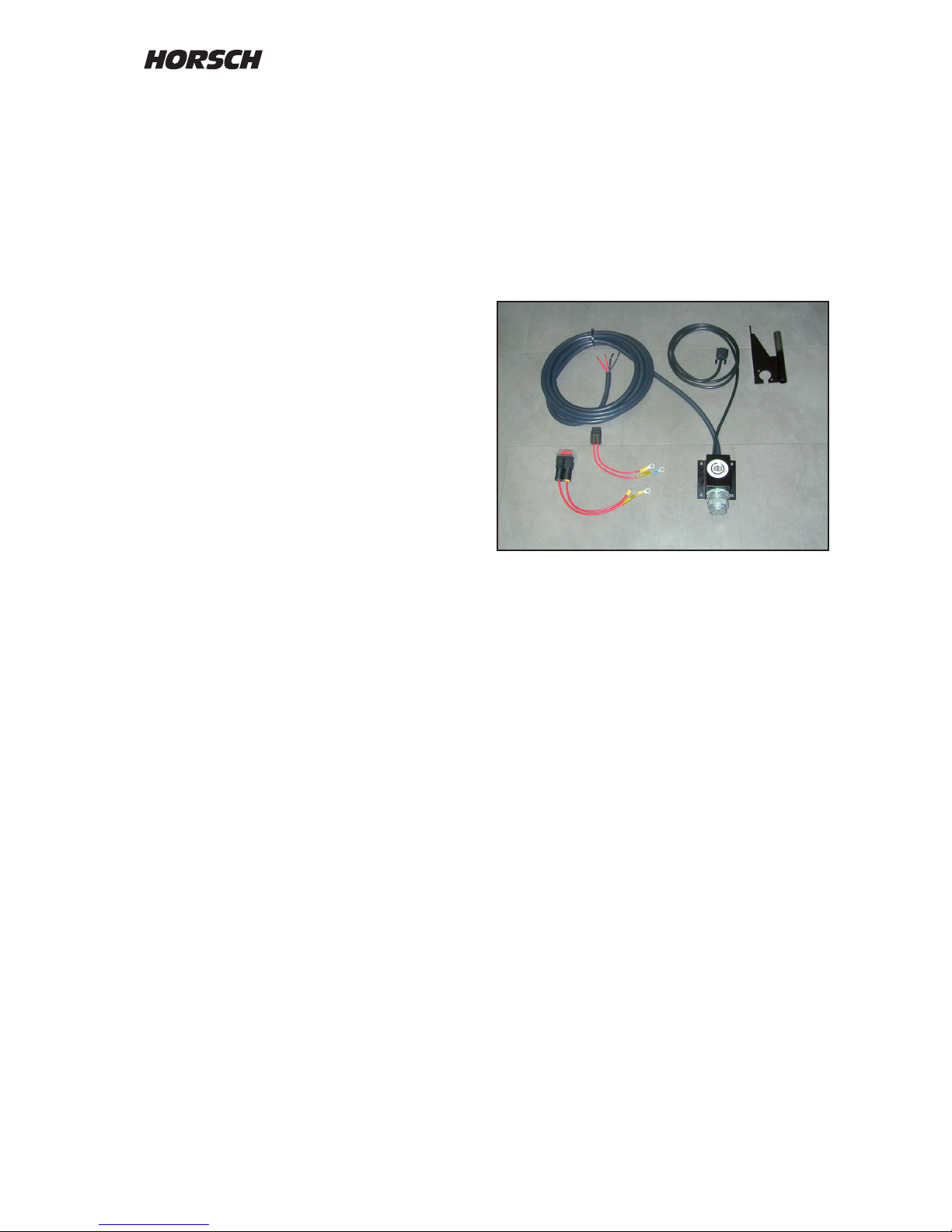
Basic equipment ISOBUS
The battery connections must have good contact. Assembly faults will lead to voltage drop
and indenable error messages and failures.
¾ Assemble the terminal bracket in a suitable
place within the view and the operating range
of the driver.
¾ Fasten the ISOBUS socket in a suitable place
at the rear end of the tractor.
¾ Route the thick cable to the battery, extend
it if necessary.
¾ Connect both fuse holders tightly and durably
with the cable.
¾ Connect the two red cables tightly with battery
plus and the two black cables with battery
negative.
¾ Plug the connecting cable in at the bottom of
the terminal.
Page 12
10
Terminal
The terminal is plugged on the pre-assembled
bracket in the tractor and connected to the
computer by means of a cable.
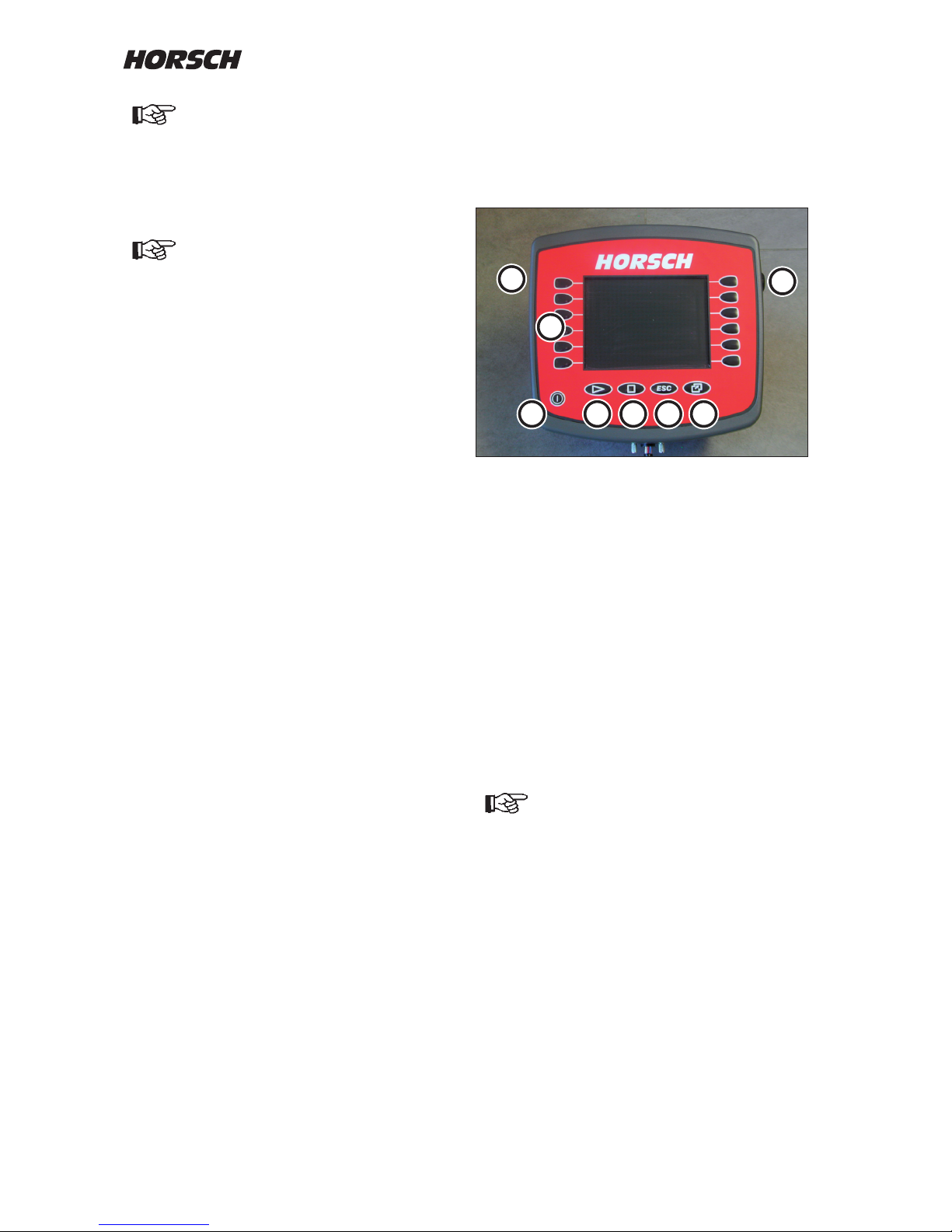
Terminal with colour display and keyboard
1. On/O button
2. Function keys
3. not assigned
4. not assigned
5. ESC-button
- Cancel input
- Exit mask
- Hide warning messages and alarms
6. Invoking / exiting selection menu
7. Rotary button
- Selection, input and conrmation
8. Connection of USB plug
The keys (2) on the display have no fixed
functions assigned to them. They will always
switch the function currently displayed.
The displayed screen contents may
vary from the illustration depending on
the respective program version.
4
3
1
2
7
6
8
5
The cables must under no circumstances be connected to any other
plugs in the cab.
The plugs are unable to transfer the
required current (A). Voltage losses
and drilling faults will occur.
The terminal should not obstruct the
eld of vision to the road.
Page 13

11
Operation
Switching on
Press the "On/O" button momentarily.
After a ne w star t and af ter changing or
reprogramming the computer the data will be
loaded from the computer.
Restart the system
Once the terminal has been connected to the
ISOBUS of the tractor, the computer is not
automatically restarted when the terminal is
switched o and on.
To rest art the system you mu s t
disconnect the connecting cable to the
machine for a short moment.
It is highly recommended to make a note of the
machine and adjustment data before running
an update.
In case of update of minor extent the data will
be maintained.
With extensive updates and if new graphics
have to be displayed, the old adjustment and
performance data may be lost.
With some system dependent faults it may be
necessary to delete the control masks from the
terminal and to upload these again from the
computer by restarting.
The pool will in this case saved again in the
terminal.
Deleting the pool
Choose the "Service" area. In the menu "File
management" select "Pools" and delete the rst
le for the drill and the second le for the single
grain metering.
The switch the terminal o for a moment. The
masks will be loaded new during a restart.
Page 14
12
Terminal settings
The settings for the terminal:
¾ brightness /display)
¾ volume (alarm)
¾ date / time
¾ language selection
¾ measuring units
¾ keyboard illumination
are set in the "Service" menu option.
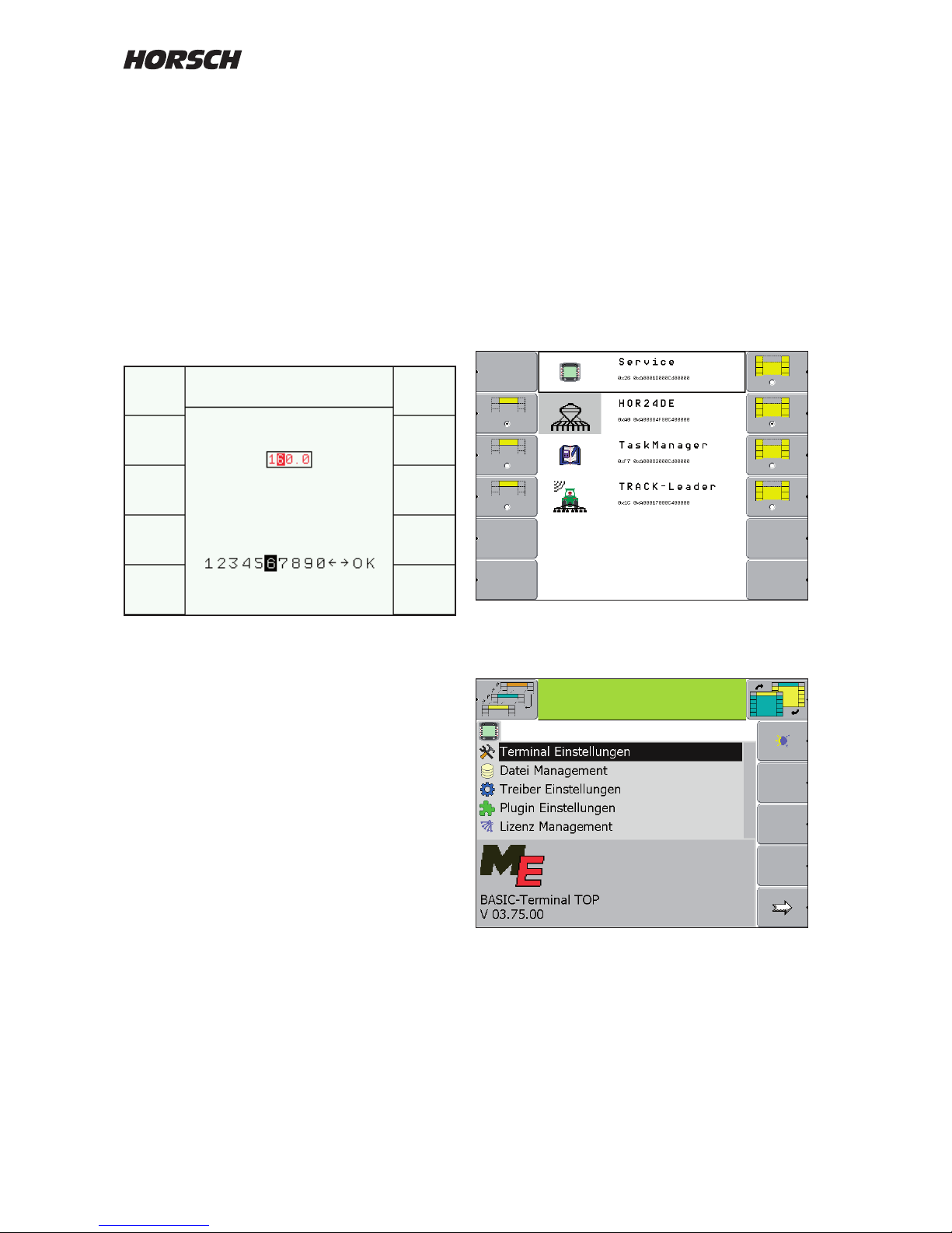
Press button (6) to open the selection menu.
Turn the rotary wheel to mark and confirm
"Service".
Turn the rotary wheel to mark and confirm
"Terminal setting".
Setting and changing inputs
Before initial start-up some settings must be
entered in to the system.
The selection, input and conrmation of text or
numericals is accomplished via the rotary button.
Use the rotary button to place the marking over
the numerical or the term and press the rotary
button to conrm.
For the terms / words all selectable possibilities
appear, for the numericals the table with the
numbers 1 - 10 with two arrows and OK.
Changing numerical values
If the number is not to be changed, press the
rotary button to conrm the number.
To change the number with the rotary button
select the desired number and press the rotary
button to conrm.
The system will automatically change to the
next number.
With the arrow keys the desired cipher can be
directly selected.
For the terms mark the new term / word with the
rotary button and press to conrm.
Page 15

13
Place and conrm the marking with the rotary
wheel.
Turn the rotary wheel to change the value or
e.g. choose the country specic language and
conrm again.
e.g. language selection
Adapt the settings for brightness, contrast and
keyboard illumination to the light conditions and
your personal appreciation.
Set the volume as loud as possible. Alarm
messages should be audible in your tractor,
even when used in the eld.
Once the settings have been made the terminal
must be switched o and on again.
Depending on the changes, e.g. in language or
the measuring units, the terminal must rst load
the new language or measuring units from the
computer of the machine.
The following languages are currently available:
German de
English en
French fr
Danish da
Polish pl
Czech cs
Romanian ro
Spanish es
Swedish sv
Hungarian hu
Serbian sr
Russian ru
Estonian et
Lithuanian li
Latvian lv
Bulgarian bg
Croatian hr
Finnish
Italian it
Settings and activation for GPS functions like
- Task Manager
- TRACK Leader II
- Section Controll etc.
are described in a dedicated instruction manual.
Page 16
14
ed sep 08
DatumEntw.DateinameZeichnungsnummer
ed sep 08
DatumEntw.DateinameZeichnungsnummerMaschine Zeichnung
ed sep 08
DatumEntw.DateinameZeichnungsnummer
ed sep 08
DatumEntw.DateinameZeichnungsnummerMaschine Zeichnung
ed sep 08
DatumEntw.DateinameZeichnungsnummerMaschine Zeichnung
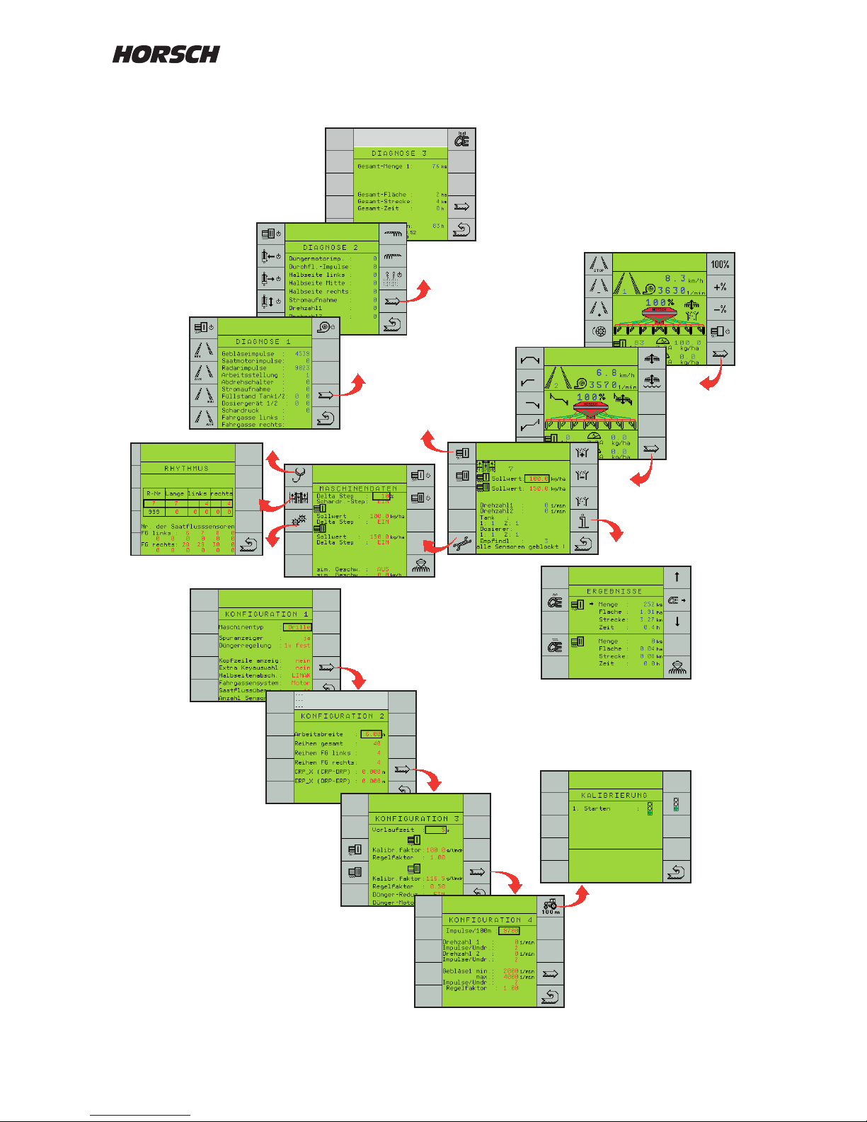
Menu overview
Start
Diagnostic
Work screens
Machine data
for calibration
Performance data
Drive a distance of 100 m
Setting the tram lines
5 sec.
Page 17
15
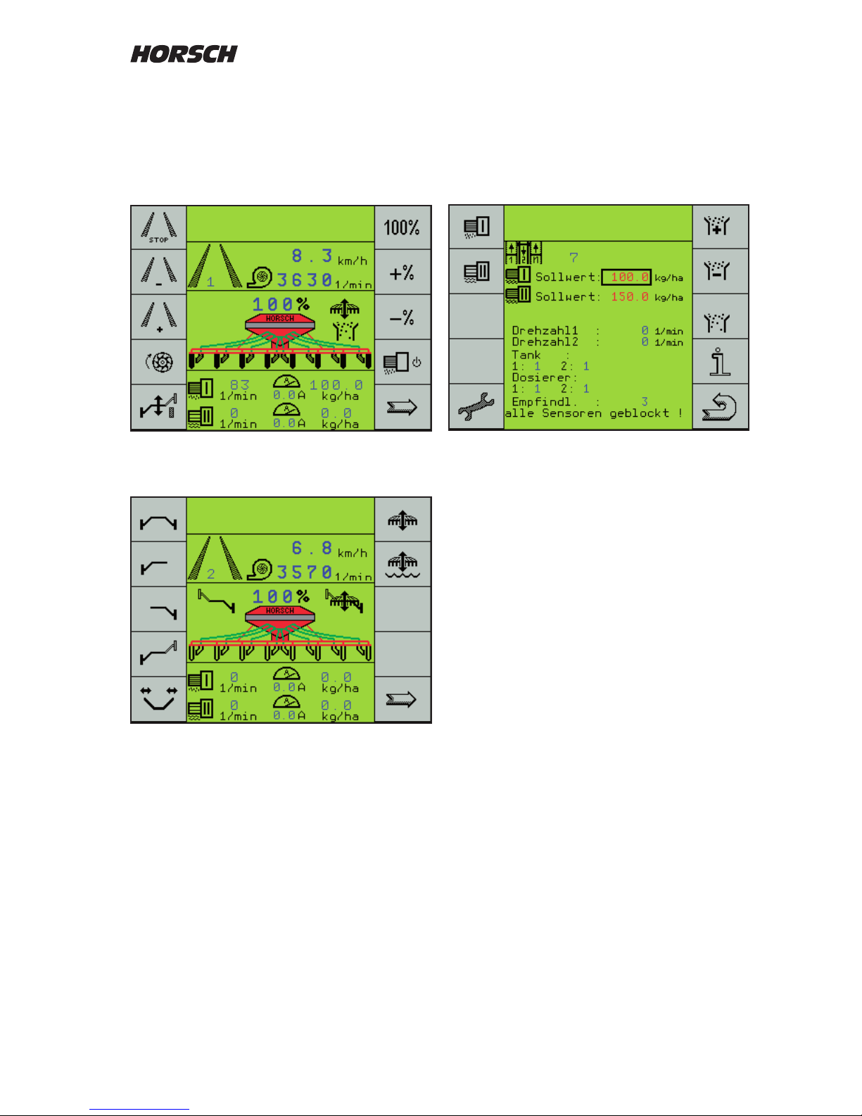
Page three of the work mask is mainly needed
for calibration, to adjust the sensitivity of seed
ow monitoring during operation and for trouble
shooting in case of blockage and with defective
sensors.
Page three of work mask
Pages two and three of the work masks
automatically return to the rst page after
10 seconds during drilling.
The arrow key can also be used to scroll back
to page one.
Adapting the work screen
The rst page of the work screen can be adapted
to your own wishes and practical use, whenever
required.
In this case a new display page is placed in front
of the rst standard page.
You can congure this page yourself in the
menu "Machine configuration" under menu
option "extra key selection" (see machine
conguration).
Screen display work mask
After switching on page one of the work mask
will always be displayed.
The displayed image will always depend on the
setting and the available equipment.
Page one of work mask
Work mask second page
Page 18
16
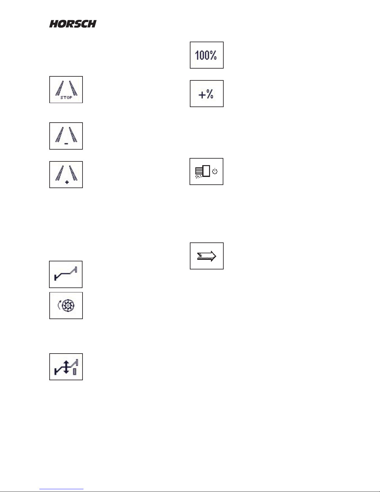
Function symbols
The symbols in the display represent the
functions of the corresponding keys.
Stop button for tram line:
The button prevents the rhythm
being switched further after the
machine has been lifted out of
work. The function is indicated with
STOP between the tracks.
The tram line rhythm is increased
by one track with every operation
of the key.
The track number is displayed
between the tracks.
In case of a tram line track the
switched tracks are black under
laid.
In addition, the closed coulter rows
no longer appear in the display
during the sowing.
If the machine is equipped with the hydraulic bout
marker control, the symbol for the alternating
bout marker will appear instead of the
"Tram Line +" symbol when pressing "STOP
Tram Line".
This button can now be used to
change the side for the bout marker.
If stationary with the drill lowered
by pressing the meter fill dril l
function, the metering unit will start
up over a specified time. If the
computer receives a speed signal
during this period, the computer will
take over the control.
Post mode:
The po s t mode disa b l e s the
hydraulic "Lifting" function.
When operating the control unit only
the bout marker will be hydraulically triggered.
The machine remains in working position. The
work signal is hydraulically blocked and the tram
line will not count on.
Seed quantity 100 %:
If the seed quantity had been
adjusted with the +% or -% keys,
pressing this key will switch back to
the default seed quantity in kg/ha.
With the adjustment keys +% or -%
the seed quantity can be set and
reset in several steps.
The seed quantity is displayed in % by the
display above the hopper. The percentage step
can be changed in the machine data. There you
can also select whether only the seed quantity
is to be changed, or also the fertiliser quantity.
Switching the drill function ON / OFF:
With the drill function switched o
the display will show STOP under
the drill.
If the drill function is switched on,
the drill is lowered to work position
and the computer receives a speed
signal,
the computer will start the control
process.
Continue to next page:
If the hydraulic bout marker control
or the half width control is activated,
the next page will show the menu
for bout marker control, lifting and
folding of the machine half width
switch o.
Page 19
17
Bout marker and hydraulic
control
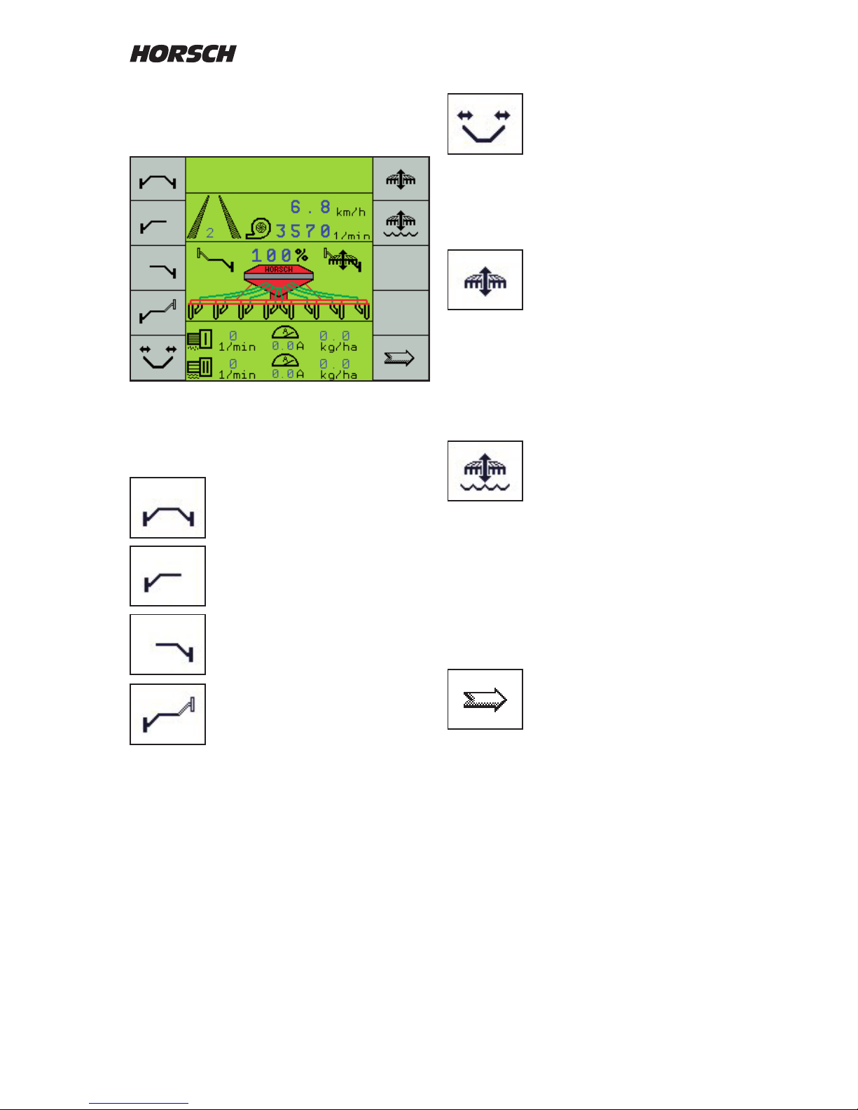
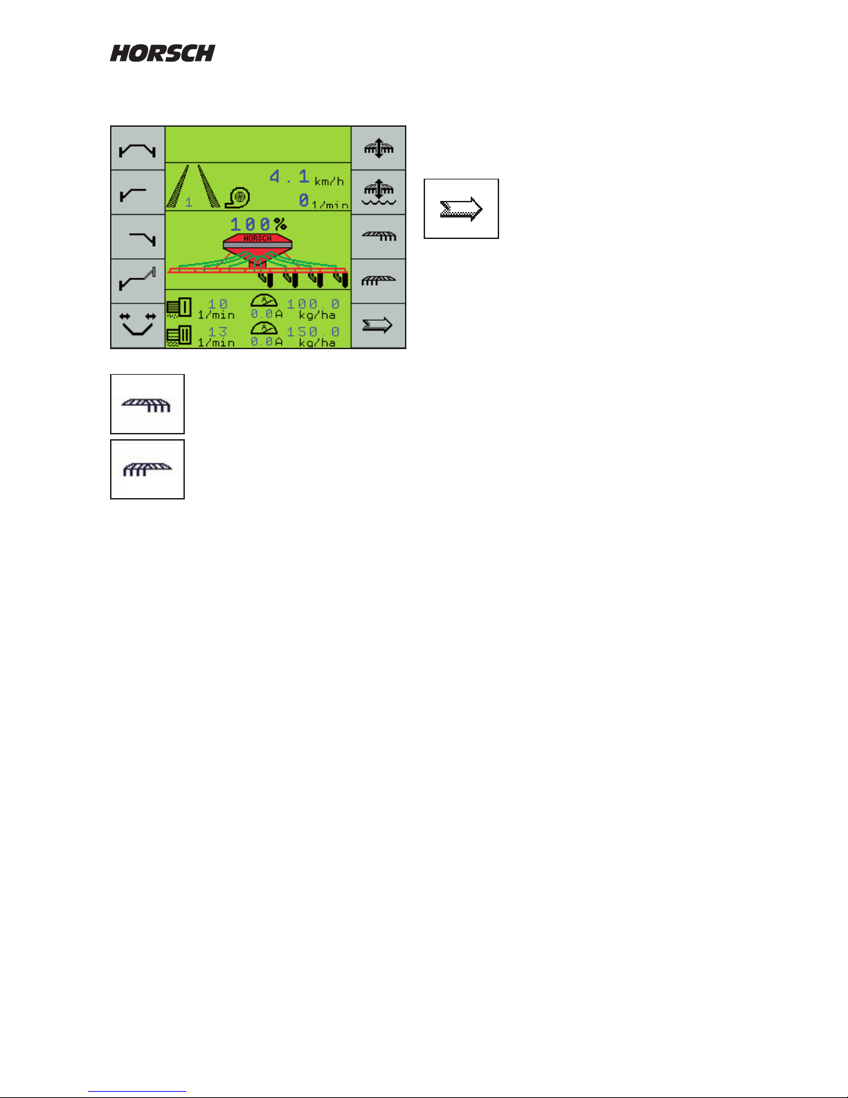
Menu image second work page - hydraulic functions
The enabled functions appear in the display
next to the drill.
Both bout markers are lifted out or
lowered together with the machine.
Only the left hand bout marker will
be operated.
Only the right hand bout marker will
be operated.
Alternating mode: Left and right
hand bout markers lift and lower
alternately.
This is the normal drill work mode.
When switching on this bout marker control also
always activates the hydraulic "Lifting" function.
Folding / unfolding the machine
With all foldable machines this key is used to
switch the hydraulic valve block over to "Folding".
The functions "Lifting / Lowering" and the drill
function are switched o.
Lifting and lowering the machine
The function "Lifting / Lowering" is automatically
activated when activating the bout marker
function. If the bout marker is switched on, the
rst actuation of the key will switch o the bout
marker and the second actuation will disable the
"Lifting / Lowering" function.
"Wet hole" function
In certain situations, e.g. if the machine sinks in
at very wet patches in the eld, this function can
be used to raise the machine. The work signal
is thereby not interrupted and the tram line will
not switch further.
Return to the normal drill function by pressing
the key again and by pressing the key for the
desired bout marker function.
Continue to next page
Page 20
18
The signals for both end positions are transmitted
from the motor to the computer. The signal for
middle position is switched by the sensor on the
metering unit.
Continue to next page
Half width shut off
After selecting the half width shut
o in the machine conguration, the
two symbols for left and right hand
on the second work page.
As soon as a key for shutting down a half width
is pressed, the corresponding half width will ash
in the displayed graph, until the sensor sends
a signal to the computer when end position is
reached.
In end position the closed half width is hidden.
The seed quantity is reduced by half, the seed
quantity display in kg/ha remains unchanged,
because the working width has also been
halved.
After pressing the same key again the total
working width is available again and the display
shows the complete machine.
Page 21
19
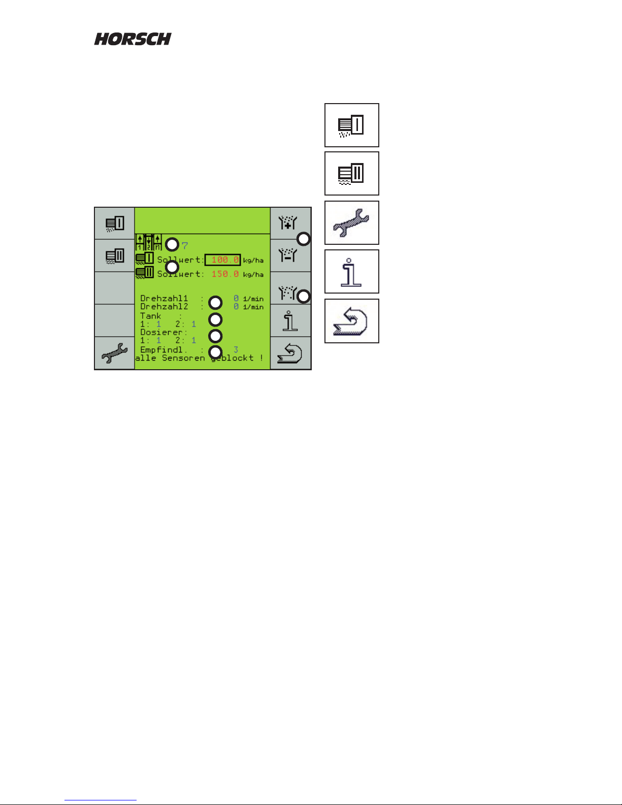
Turning o solid fertiliser
(twin hopper version)
Machine data
Back to rst page
Result display
Turning o seed
Third page with seed ow monitoring
Depending on the design of the drill, e.g. with
twin hopper, liquid fertiliser facility or seed ow
monitoring, further symbols will appear on the
third "work page".
Her e you find th e display s that are no t
permanently needed during sowing.
The keys can be used to switch over to further
functions.
Display readings
1. The number of the tram line rhythm from the
table - not the number of bouts.
2. Nominal value of seed quantity in metering
unit I. With twin hopper the fertiliser quantity
in metering unit II or the liquid fertiliser
quantity.
3. RPM-meter for two shafts.
4. Hopper 1 - lling level indicator for seed
hopper. Hopper 2 - lling level indicator for
fertiliser hopper. Display 1 = full, 0 = not full
(lling level below sensor height).
5. Monitoring of metering units, e.g. in case of
bridging in seed or fertiliser hopper. Display
1 = full, 0 = metering unit empty.
6. Sensitivity setting for seed ow monitoring
and display of blocked seed hoses.
7. Plus and minus key to set the sensitivity of
seed ow monitoring.
8. Switch-over to the seed flow monitoring
diagnostics.
From this page you can switch to further menus.
4
3
5
1
2
6
7
8
Page 22
20
ed sep 08
DatumEntw.DateinameZeichnungsnummer
ed sep 08
DatumEntw.DateinameZeichnungsnummer
ed sep 08
DatumEntw.DateinameZeichnungsnummerMaschine Zeichnung
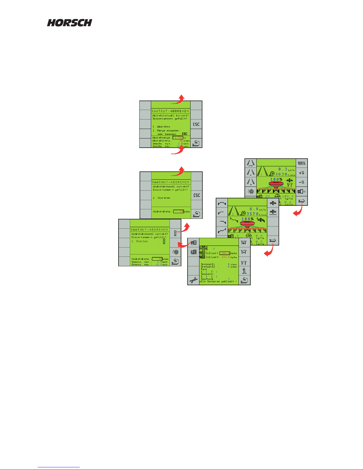
Menu overview Calibration
Start
Operate the calibration switch
ed sep 08
DatumEntw.DateinameZeichnungsnummerMaschine Zeichnung
ed sep 08
DatumEntw.DateinameZeichnungsnummerMaschine Zeichnung
Calibration
Weigh the calibration sample
Enter the weight
Check the speed range
ed sep 08
DatumEntw.DateinameZeichnungsnummerMaschine Zeichnung
Page 23
21
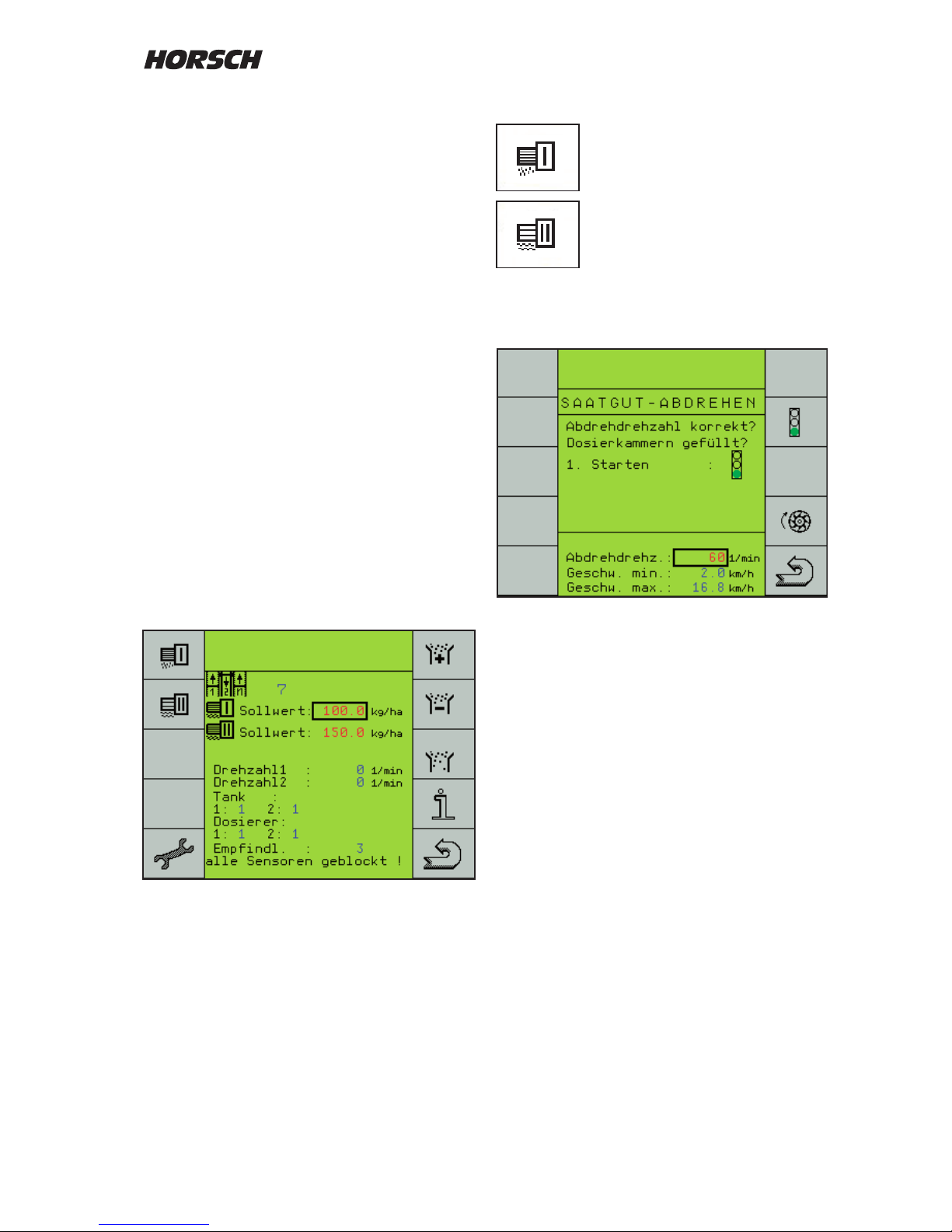
Calibration
Seed calibration - metering unit 1
Fertiliser calibration - metering unit 2
Press key "Calibration metering unit 1".
The menu for turning o the seed is displayed.
The display reminds you about the setting of the
metering unit calibration speed and the lling of
hopper and metering unit.
Calibration speed?
The calibration speed can be selected with the
"Return"-key and set with the + and - keys.
The default setting is 60 revolutions per minute.
This is sucient under normal conditions.
If work is carried out mainly at high metering
sp eed s, the calibration sp eed should be
increased to enable almost similar lling of the
metering cells.
Seed calibration
Before starting the seed calibration the setpoints
for seed and metering quantities must be entered
to enable calculation of the working speed.
The metering unit must have the correct rotor
installed.
Rotor selection
The rotor is dependent on seed quantity. working
speed and working width of the drill.
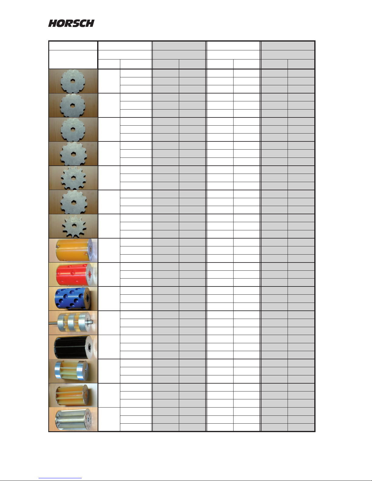
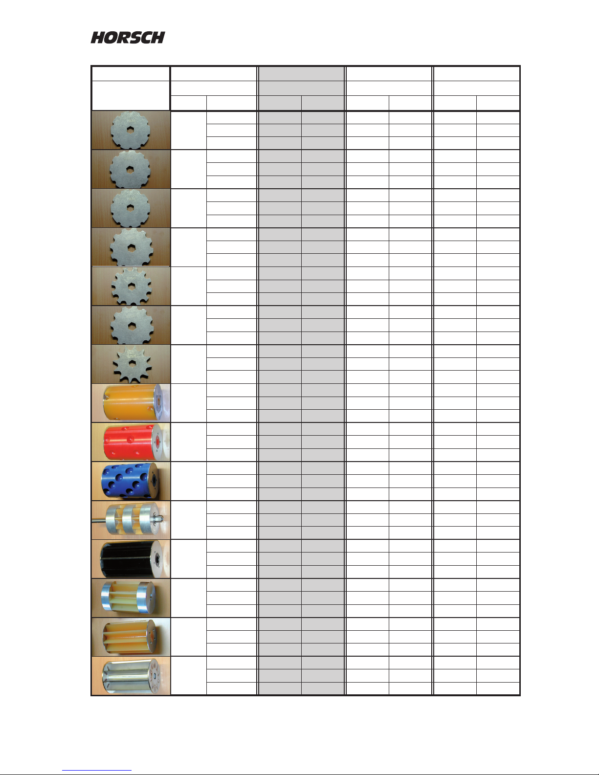
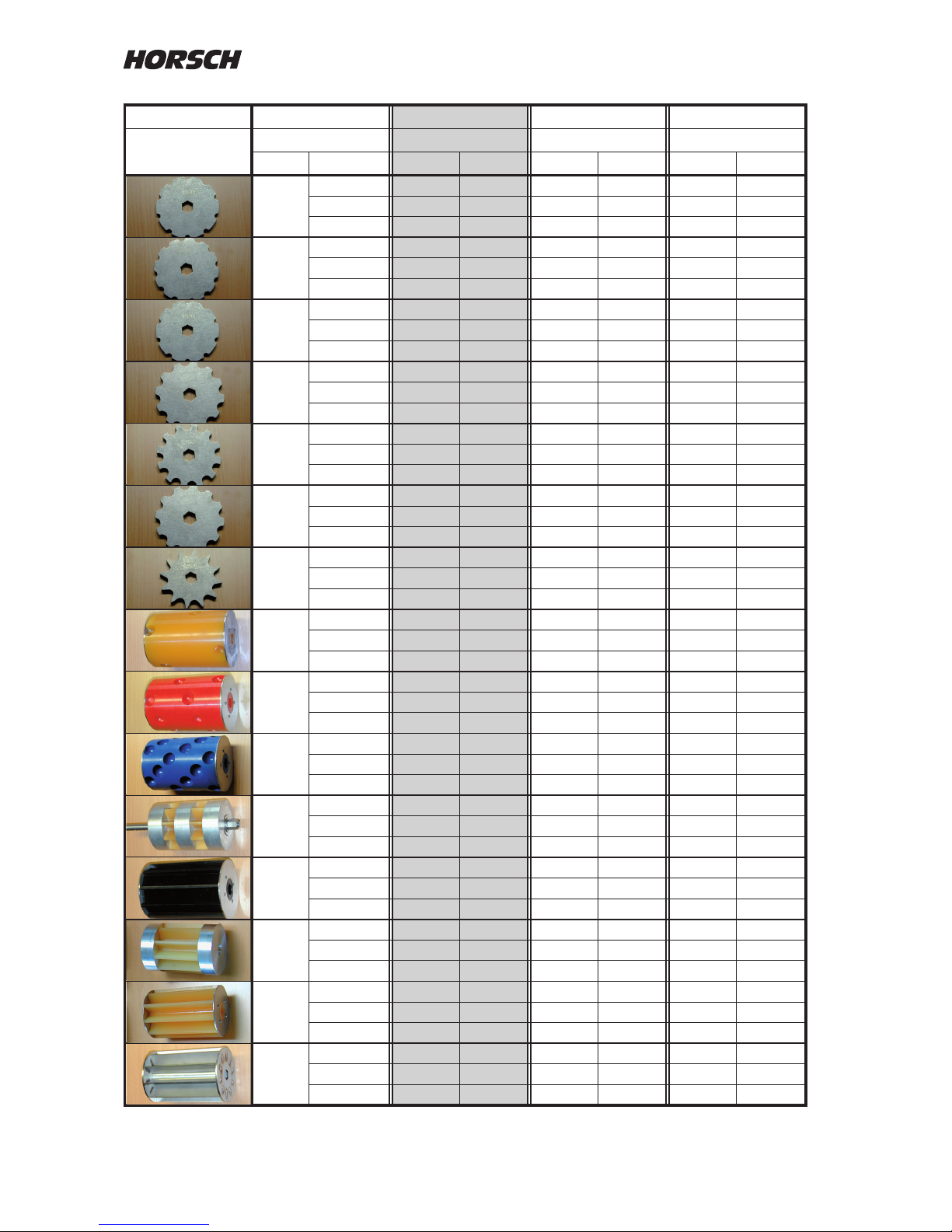
The following tables show the minimum and
maximum seed quantities ate various working
widths and the available rotor sizes for working
speeds of 5, 10 and 15 km/h.
Other rotor sizes for special applications are
available on request.
The setting tables are based on 1 kg/litre With
all types of seeds the specic weight must be
taken into account and according to this, e.g. a
larger rotor must be installed in case of a lower
seed weight.
Entering the set value
At "Setpoint" select the metering unit for seed
and fertiliser and enter the required seed or
fertiliser quantity in kg/ha with the + and - keys.
Page 24
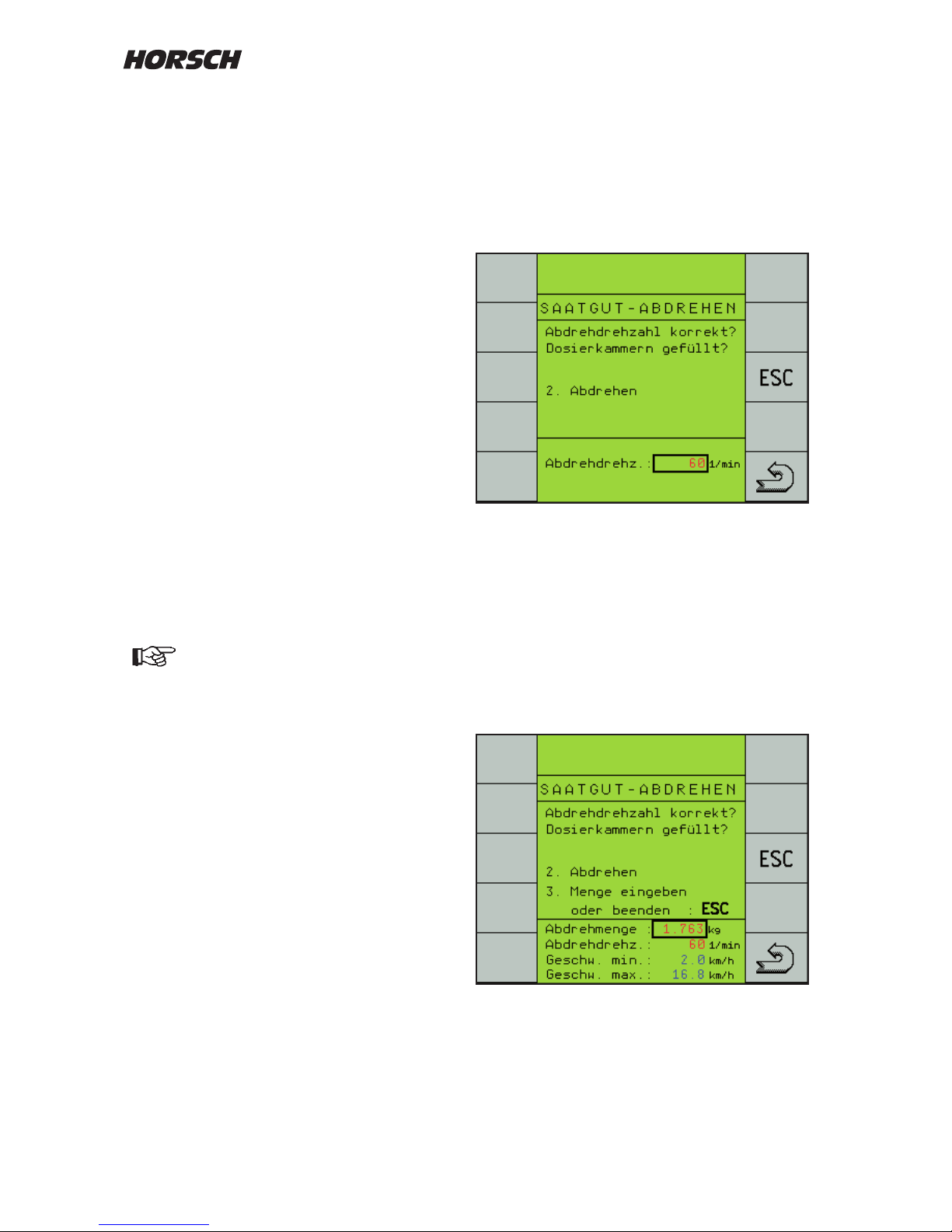
22
Starting calibration
Place a container or attach a calibration bag
under the metering unit, depending on the
machine.
Press the trac light button to start.
A second page "Calibration" appears.
With the "ESC"-key you can abort the process
at this point and start it anew.
The "Return"-key brings you back to the work
page.
¾ Operate the calibration switch on the machine.
The rotor turns and fills the calibration
container.
¾ After switching o calibration the menu to
enter the calibration quantity appears.
Metering unit lled?
The hopper must be suciently lled with seed
before starting the calibration process. However,
the hopper should not be lled completely; this
applies particularly for ne seeding, to enable
easier exchange of rotor if it has been incorrectly
selected.
For correct calculation of the seed quantity all
cells in the rotor should be lled when starting
the seed calibration.
For this purpose press the key "Metering Unit".
The rotor will rotate as long as specied in the
"Conguration 3" menu under "prime rotor time",
or until the key is pressed again.
Calibration quantity
During the "Seed calibration" the computer
receives the calculation information required for
exact metering control.
It requires the seed weight taken from the
metering unit during seed calibration as input
value.
In order to keep measuring inaccuracies low, as
much seed as possible should be metered out.
Before the seed calibration you must
check and possibly clean the Venturi
area and the connected pipes from any
seed deposits. Residues falsify the
calibr ation quantity and th us the
complete drilling.
Page 25
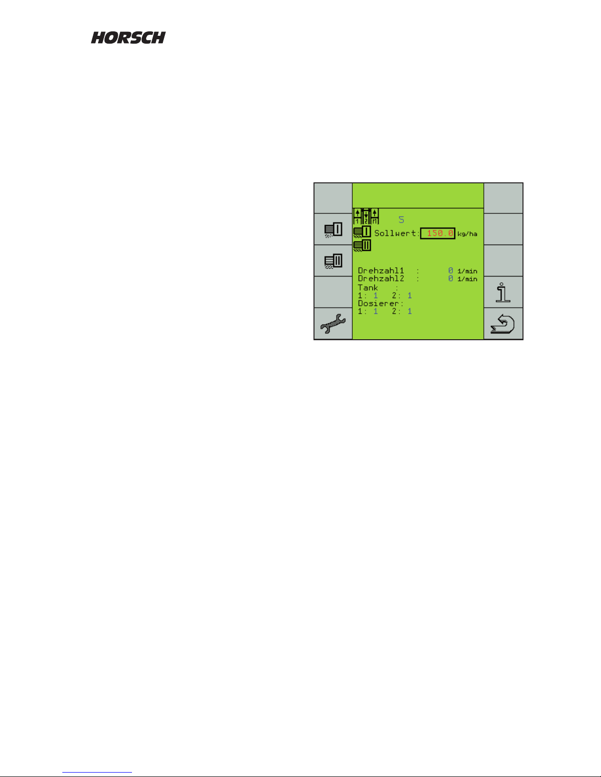
23
¾ Remove the calibration container and remove
any seeds that may have remained in the
Venturi area.
¾ Weigh the calibrated seed.
¾ Press the "Enter"-key to select "Calibration
quantity" and enter the weight with the +
and - keys.
¾ After entering the calibration weight the
possible speed range will be calculated and
displayed.
If the displayed speed range corresponds with
your desired drill speed, you may start the
fertiliser calibration or, in case of single hopper,
start the sowing process.
If the desired working speed is not within the
predetermined range, the rotor must be replaced
by a bigger or smaller one, as required.
The calibration process must in this case be
repeated.
The metering motor can be regulated between
15 rpm and 150 rpm.
At speeds higher than 135 rpm a warning will
be displayed, stating that the rotary speed is
too high. At higher speeds uniform lling of the
metering cells can no longer be guaranteed.
Speeds ranging from 60 to 100 rpm have been
found to be most favourable for many
types of seeds.
Calibration when joining hoppers
(Both hoppers are used for seed)
On machines with twin hopper both hoppers can
be used for the drilling of seed.
The desired seed quantity is only entered for
metering unit 1.
However, both metering units must be calibrated
and the calibration quantities must be entered.
Calibration menu
As a reminder not to forget the second calibration
sample, the symbol of the second metering unit
ashes after the rst calibration sample.
The metering rotors do not have to be of the
same size. With two dierent rotors the smaller
one should be installed in the metering unit of
the smaller hopper.
Page 26
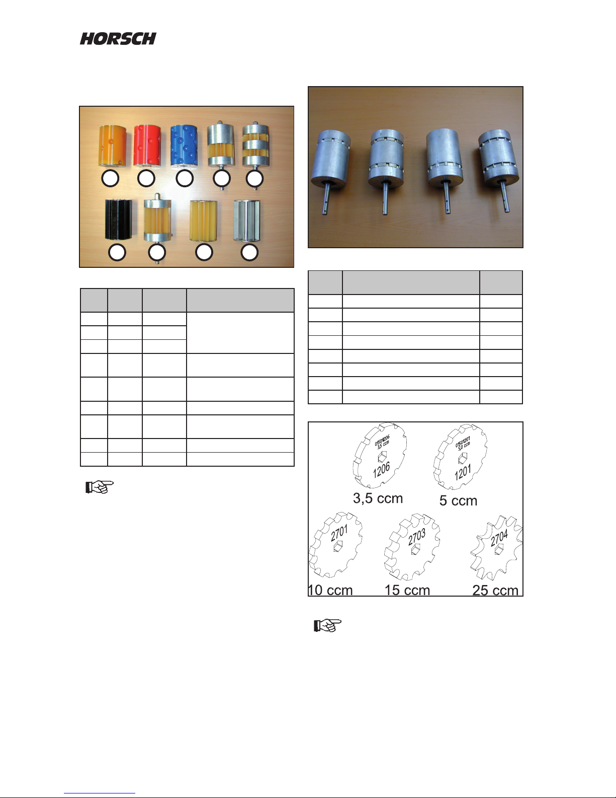
24
Rollers for small seeds
Size
cm³
Cell shape / cell size Number
of cells
3.5 half-round, radius 4 mm 10
7 2 cell discs 3.5 cm³
5 Groove depth approx. 19 x 3 mm 12
10 2 cell discs 5 cm³
10 Groove depth approx. 23 x 5 mm 12
20 2 cell discs 10 cm³
15 U-shape, radius 7 mm 12
25 V-shape, radius 7 mm 12
On machines with double Venturi area
and 2 seed towers you may only use
rotors with 2 cell discs.
Oth e rwise the see d is unev e nly
distributed to the two halves.
5
1
3
8
7
6
2
4
4a
Rotor selection
Roller for seed and fertiliser
No. Size
cm³
Colour
1 20 yellow
- suitable for maize
- not suitable for beans
and solid fertilisers.
2 40 red
3 100 blue
4
170 yellow /
alu
4a 170
yellow /
alu
2 x 85 cm³ for double
Venturi area
5 250 black
6
320 yellow /
alu
7 500 yellow
8 800 metal
On machines with double Venturi area and
2 seed towers the rotor 4a (2 x 85 cm³)
must be used when using the type
170 rotor.
Oth e rwise the see d is unev e nly
distributed to the two halves.
Page 27
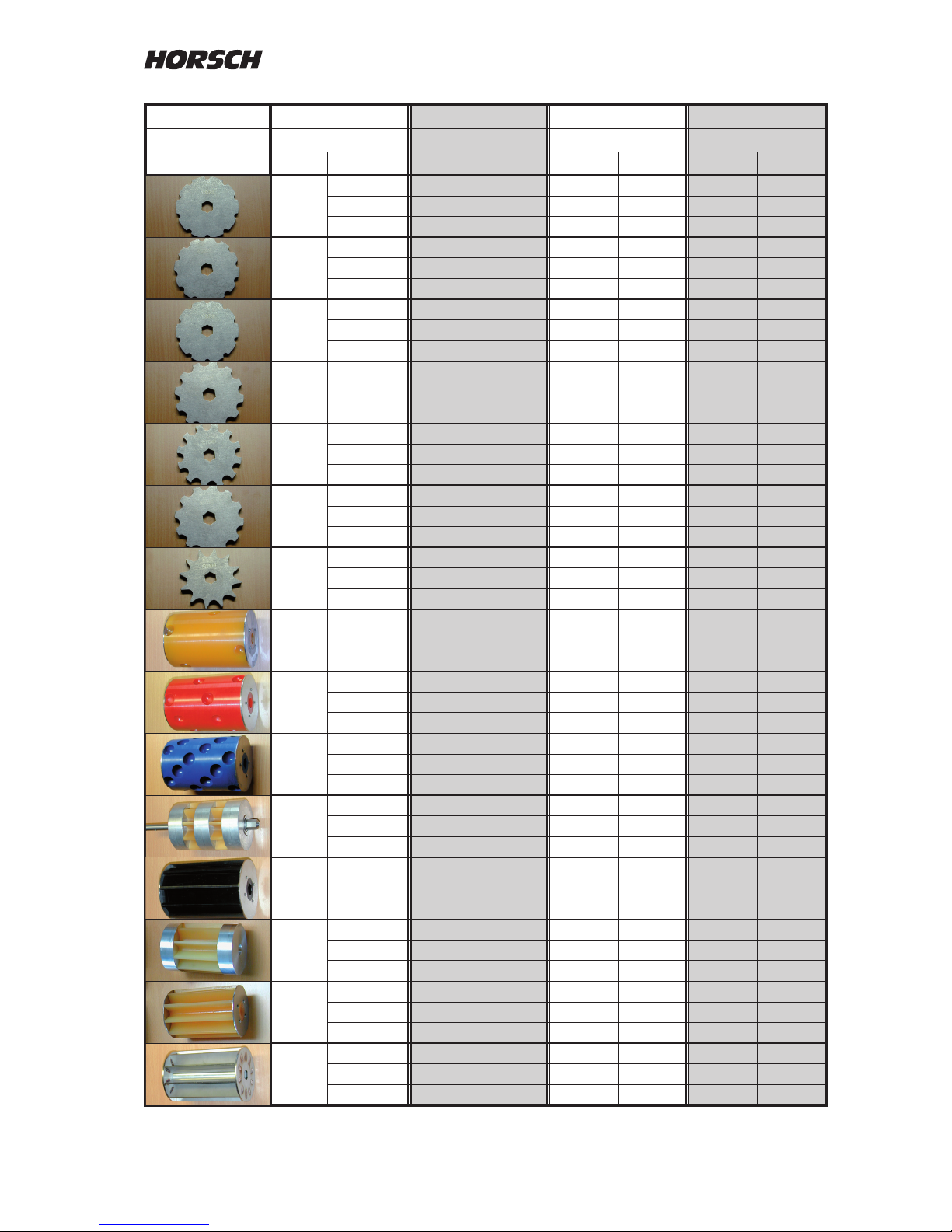
25
Rollers Working width 3 m 3.5 m 4 m
Seed quantity kg/ha Seed quantity kg/ha Seed quantity kg/ha
Roller Speed min max min max min max
3.5
5 2 18 2 15 2 13
10 1 9 1 8 1 7
15 1 6 1 5 1 4
5.0
5 3 25 3 21 2 19
10 2 13 1 11 1 9
15 1 8 1 7 1 6
7.0
5 4 35 4 30 3 26
10 2 18 2 15 2 13
15 1 12 1 10 1 9
10
5 6 50 5 43 5 38
10 3 25 3 21 2 19
15 2 17 2 14 2 13
15
5 9 75 8 64 7 56
10 5 38 4 32 3 28
15 3 25 3 21 2 19
20
5 12 100 10 86 9 75
10 6 50 5 43 5 38
15 4 33 3 29 3 25
25
5 15 125 13 107 11 94
10 8 63 6 54 6 47
15 5 42 4 36 4 31
20
5 12 100 10 86 9 75
10 6 50 5 43 5 38
15 4 33 3 29 3 25
40
5 24 200 21 171 18 150
10 12 100 10 86 9 75
15 8 67 7 57 6 50
100
5 60 500 51 429 45 375
10 30 250 26 214 23 188
15 20 167 17 143 15 125
170
5 102 850 87 729 77 638
10 51 425 44 364 38 319
15 34 283 29 243 26 213
250
5 150 1250 129 1071 113 938
10 75 625 64 536 56 469
15 50 417 43 357 38 313
320
5 192 1600 165 1371 144 1200
10 96 800 82 686 72 600
15 64 533 55 457 48 400
500
5 300 2500 257 2143 225 1875
10 150 1250 129 1071 113 938
15 100 833 86 714 75 625
800
5 480 4000 411 3429 360 3000
10 240 2000 206 1714 180 1500
15 160 1333 137 1143 120 1000
..1206
..1201
2x ..1206
..2701
..2703
2x ..2701
..2704
Page 28
26
Rollers Working width 6.0 m 7.5 m 8 m
Seed quantity kg/ha Seed quantity kg/ha Seed quantity kg/ha
Roller Speed min max min max min max
3.5
5 1 9 1 7 1 7
10 1 4 0 4 0 3
15 0 3 0 2 0 2
5.0
5 2 13 1 10 1 9
10 1 6 1 5 1 5
15 1 4 0 3 0 3
7.0
5 2 18 2 14 2 13
10 1 9 1 7 1 7
15 1 6 1 5 1 4
10
5 3 25 2 20 2 19
10 2 13 1 10 1 9
15 1 8 1 7 1 6
15
5 5 38 4 30 3 28
10 2 19 2 15 2 14
15 2 13 1 10 1 9
20
5
6 50 5 40 5 38
10
3 25 2 20 2 19
15
2 17 2 13 2 13
25
5 8 63 6 50 6 47
10 4 31 3 25 3 23
15 3 21 2 17 2 16
20
5 6 50 5 40 5 38
10 3 25 2 20 2 19
15 2 17 2 13 2 13
40
5 12 100 10 80 9 75
10 6 50 5 40 5 38
15 4 33 3 27 3 25
100
5 30 250 24 200 23 188
10 15 125 12 100 11 94
15 10 83 8 67 8 63
170
5 51 425 41 340 38 319
10 26 213 20 170 19 159
15 17 142 14 113 13 106
250
5 75 625 60 500 56 469
10 38 313 30 250 28 234
15 25 208 20 167 19 156
320
5 96 800 77 640 72 600
10 48 400 38 320 36 300
15 32 267 26 213 24 200
500
5 150 1250 120 1000 113 938
10 75 625 60 500 56 469
15 50 417 40 333 38 313
800
5 240 2000 192 1600 180 1500
10 120 1000 96 800 90 750
15 80 667 64 533 60 500
..1206
..1201
2x ..1206
..2701
..2703
2x ..2701
..2704
Page 29
27
Rollers Working width 9 m 10 m 12 m
Seed quantity kg/ha Seed quantity kg/ha Seed quantity kg/ha
Roller Speed min max min max min max
3.5
5 1 6 1 3 1 4
10 0 3 0 3 0 2
15 0 2 0 2 0 1
5.0
5 1 8 1 8 1 6
10 1 4 0 4 0 3
15 0 3 0 3 0 2
7.0
5 1 12 1 11 1 9
10 1 6 1 5 1 4
15 0 4 0 4 0 3
10
5 2 17 2 15 2 13
10 1 8 1 8 1 6
15 1 6 1 5 1 4
15
5 3 25 3 23 2 19
10 2 13 1 11 1 9
15 1 8 1 8 1 6
20
5 4 33 4 30 3 25
10 2 17 2 15 2 13
15 1 11 1 10 1 8
25
5 5 42 5 38 4 31
10 3 21 2 19 2 16
15 2 14 2 13 1 10
20
5 4 33 4 30 3 25
10 2 17 2 15 2 13
15 1 11 1 10 1 8
40
5 8 67 7 60 6 50
10 4 33 4 30 3 25
15 3 22 2 20 2 17
100
5 20 167 18 150 15 125
10 10 83 9 75 8 63
15 7 56 6 50 5 42
170
5 34 283 31 255 26 213
10 17 142 15 128 13 106
15 11 94 10 85 9 71
250
5 50 417 45 375 38 313
10 25 208 23 188 19 156
15 17 139 15 125 13 104
320
5 64 533 58 480 48 400
10 32 267 29 38 24 200
15 21 178 19 267 19 133
500
5 100 833 90 750 75 625
10 50 417 45 375 38 313
15 33 278 30 250 25 208
800
5 160 1333 144 1200 120 1000
10 80 667 72 600 60 500
15 53 444 48 400 40 333
..1206
..1201
2x ..1206
..2701
..2703
2x ..2701
..2704
Page 30
28
Rollers Working width 15 m 18 m 24 m
Seed quantity kg/ha Seed quantity kg/ha Seed quantity kg/ha
Roller Speed min max min max min max
3.5
5 0 4 0 3 0 2
10 0 2 0 1 0 1
15 0 1 0 1 0 1
5.0
5 1 5 1 4 0 3
10 0 3 0 2 0 2
15 0 2 0 1 0 1
7.0
5 1 7 1 6 1 4
10 0 4 0 3 0 2
15 0 2 0 2 0 1
10
5 1 10 1 8 1 6
10 1 5 1 4 0 3
15 0 3 0 3 0 2
15
5 2 15 2 13 1 9
10 1 8 1 6 1 5
15 1 5 1 4 0 3
20
5 2 20 2 17 2 13
10 1 10 1 8 1 6
15 1 7 1 6 1 4
25
5 3 25 3 21 2 16
10 2 13 1 10 1 8
15 1 8 1 7 1 5
20
5 2 20 2 17 2 13
10 1 10 1 8 1 6
15 1 7 1 6 1 4
40
5 5 40 4 33 3 25
10 2 20 2 17 2 13
15 2 13 1 11 1 8
100
5 12 100 10 83 8 63
10 6 50 5 42 4 31
15 4 33 3 28 3 21
170
5 20 170 17 142 13 106
10 10 85 9 71 6 53
15 7 57 6 47 4 35
250
5 30 250 25 208 19 156
10 15 125 13 104 9 78
15 10 83 8 69 6 52
320
5 38 320 32 267 24 200
10 19 160 16 133 12 100
15 13 107 11 89 8 67
500
5 60 500 50 417 38 313
10 30 250 25 208 19 156
15 20 167 17 139 13 104
800
5 96 800 80 667 60 500
10 48 400 40 333 30 250
15 32 267 27 222 20 167
..1206
..1201
2x ..1206
..2701
..2703
2x ..2701
..2704
Page 31
29
Performance data
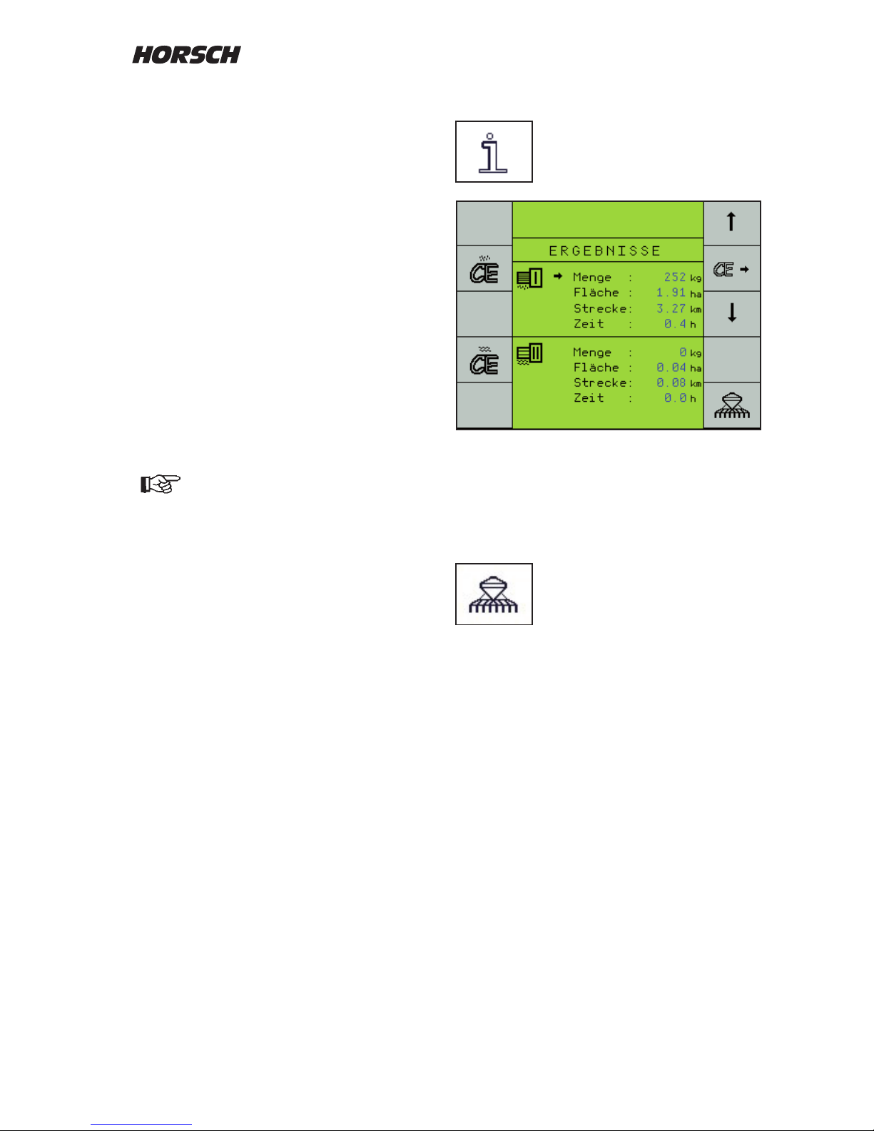
The "i"-key is used to display the
seed and area output.
These data can either be completely deleted
per metering with the left hand "CE"-keys, or
individually selected with the right hand arrow
keys and reset to "0" with the right hand
"CE"-key.
Back to the drill program:
First "work page".
Seed Check
The Seed Check is an inspection for the seed
calibration and, during the sowing process, for
the metering accuracy.
The same procedure as for seed calibration must
be performed for this purpose.
The computer retrieves the calibration data from
the last seed calibration and uses the revolutions
of the new seed calibration to calculate a new
value for the calibration quantity.
When switching o the calibration switch, it
shows this value under "Calibration quantity"
in kg.
If the same seed is used as for the previously
performed seed calibration, the weight of the
new seed calibration must be identical with the
gure on the screen.
In case of deviations correct the value
and repeat the control if required.
Page 32
30
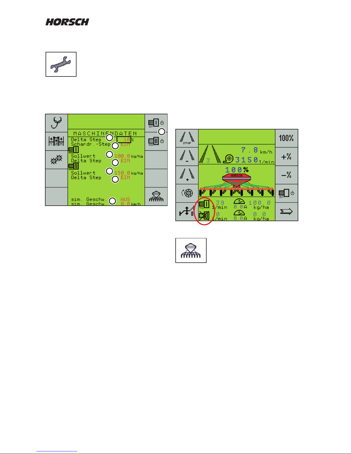
7. In case of a missing speed signal (e.g. radar
defective) an emergency program can be
switched on and sowing can be continued
with the simulation speed. The radar should
in this case be unplugged. The simulation
speed can be changed here. The metering
motor in this case runs with the same speed
as the speed specied.
8. Metering unit ON / OFF; A metering unit can
be quickly switched o and on again with
these keys. A switched o metering unit is
displayed expunged.
Back to the drill program:
First "work page".
Input of machine data
The machine data must be entered
before initial start-up of the machine.
After switching on, the rst page of the main
menu is displayed. Use the arrow key to switch
to the second page. The key for machine data
opens a further selection page.
1. Metering quantity adjustment with the + and
- % keys. The adjustment value cannot be
adjusted here.
2. Coulter pressure Step; on machines with
hydraulic coulter pressure adjustment and
extension for automatic control one can
choose here whether the seed quantity
should be adjusted together with the coulter
pressure adjustment. The seed quantity is
increased by a value set in the Delta Step
(1), when resetting the quantity adjustment
is also reset.
3. Specication of metering quantity in kg/ha
for metering unit I.
4. Switch the adjustment of metering
quantity "On" or "O" with the + and - % keys.
5. Specication of quantity for metering unit II.
Fertiliser in kg/ha or liquid fertiliser in l/ha.
6. Selection of whether the quantity of solid or
liquid fertiliser is to be adjusted with the +
or - % keys.
5
4
6
1
3
7
2
8
Page 33
31
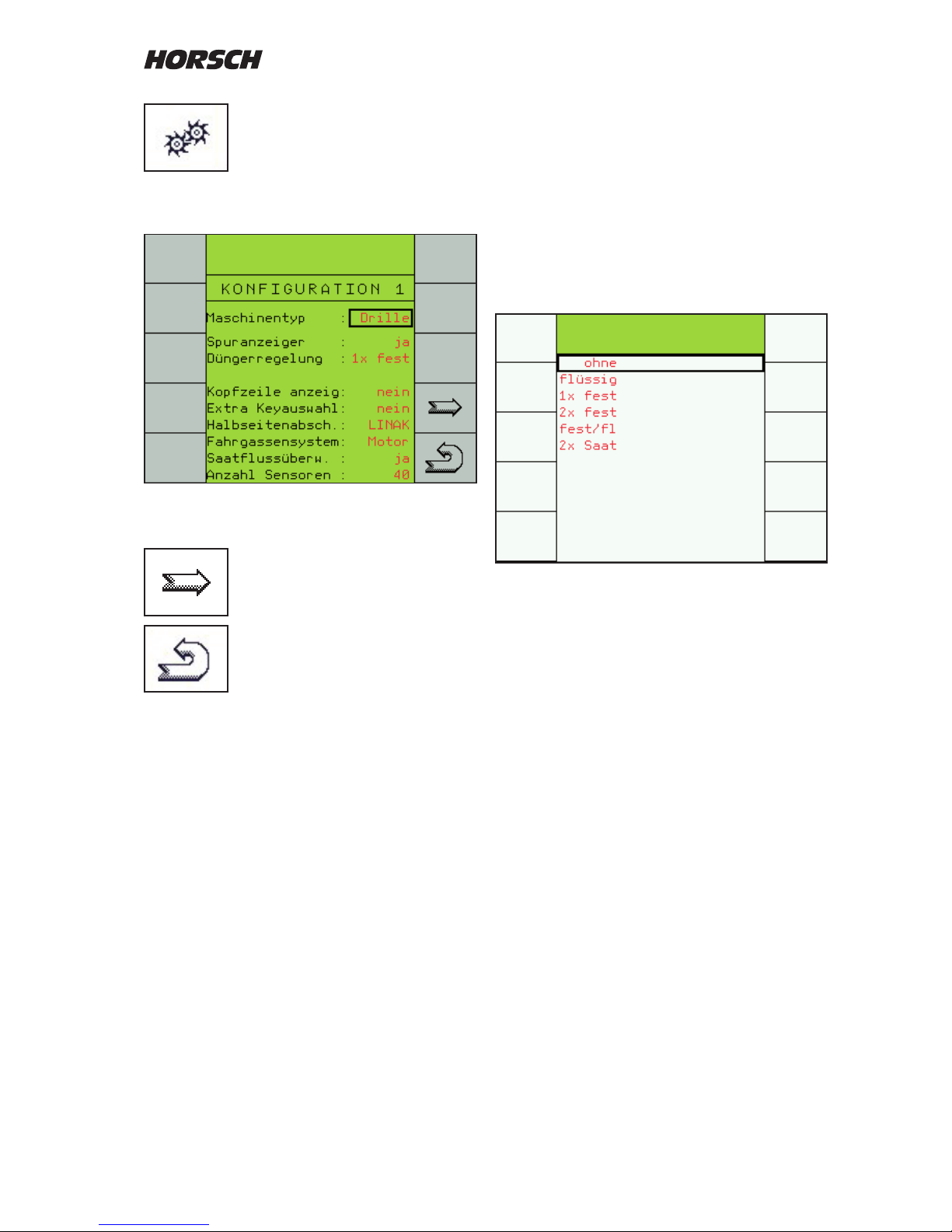
Press the "machine conguration"
key for about 5 seconds to enter
the machine data.
Conguration 1
x
x
In the next version the "bout marker"will be renamed
"Hydraulic block".
Continue to page "Conguration 2,
3 and 4"
Return to work page
Machine type
Here you can select from Drille and Maistro. The
program has been prepared for both machines.
Switching over is only required when towing a
Maistro with ME-control.
Bout marker control
The "Boutmarker" function activates the entire
hydraulic control. It must always be switched on
as soon as the hydraulic functions like lifting,
wings or boutmarkers are to be controlled via
the display.
The bout marker working mode can be selected
in the monitor.
The boutmarker function is hydraulically always
linked with the "Lift machine" function
If the "Post mode" or "Wet hole mode" functions
are active, the hydraulic control must not be
switched o, as otherwise the computer will
ignore the change in work signal and thus will
no longer switch the machine on or o.
Fertiliser control
If the machine is equipped with several hoppers
or with liquid fertiliser facility, the system must
be selected here.
Selection menu for fertiliser control
Depending on the equipment of the machine you
must choose the number of hoppers and the type
of the fertiliser to open the corresponding menus
and input possibilities in the display:
1. One seed hopper - no additional hopper for
fertiliser.
2. One seed hopper and one additional hopper
for liquid fertiliser installed.
3. One seed hopper and one additional hopper
for solid fertiliser installed.
4. One seed hopper and two additional hoppers
for solid fertiliser installed.
5. One seed hopper, one additional hopper for
liquid fertiliser and one additional hopper for
solid fertiliser installed.
6. One seed hopper and one additional hopper
for solid fertiliser installed. Both hoppers
are only used for seed. In the machine
conguration the tank sizes are entered in
relation to one another, so that both tanks will
be empty at the same time. Both metering
units must be calibrated.
4
3
5
2
1
6
Page 34
32
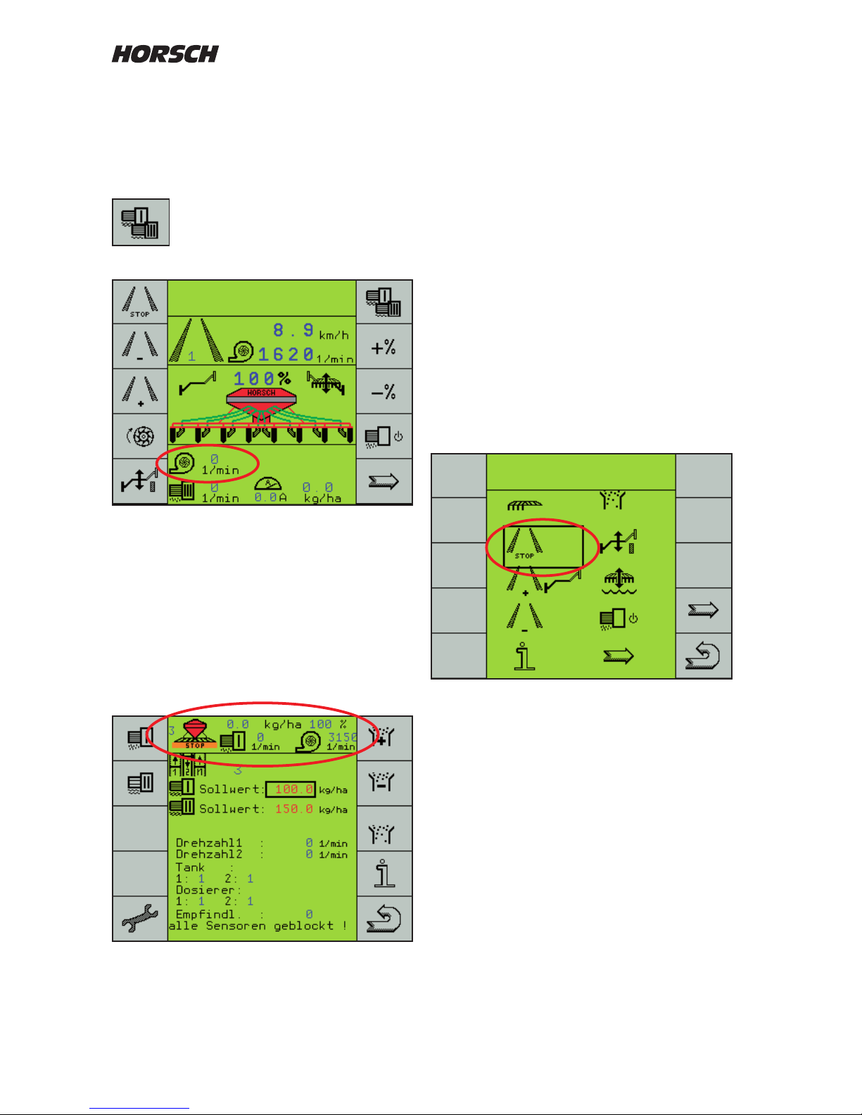
Machines with dual hopper and two fans are
equipped with a second computer to monitor
the second fan.
Switch over to the third metering drive to be able
to view the second fan speed.
Changeover from 1 / 2 metering drive
to the 3. metering drive.
Indication of the second fan speed
The seed quantity for the third drive must be
set to 0 kg/ha.
Show header
In the ISOBUS compatible terminals you can
display additional functions or, in the drill
program, the important functions in all menus.
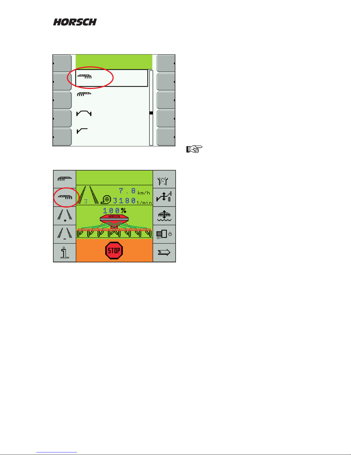
Extra key selection
Under "Extra key selection" you can congure
the rst work page yourself.
This display page is placed before the first
work page and appears with a selection of its
functions.
Setting
Choose the line "Extra key selection" and mark
"yes".
Use the arrow key to leaf through to page ve
of the machine conguration.
The view shows the work page as currently
congured.
Change of arrangement and new allocation
of functions.
Use the + / - keys to move the frame to the
location that should have another function
assigned.
Page 35
33
Press the "Enter" key. A list with all possible
functions appears.
After selecting all functions the work screen may
appear e.g. in this conguration.
Half width control
If a half width control is installed you must select
LINAK or WINGS as control, depending on the
system.
Tram line system
In the tram line system one must choose
between "Magnet" and "Motor".
The magnetic valves are switched on by
permanent current.
The motors receive 3 seconds current to close
the valves and are energized for 3 seconds in
opposite direction to open the valves
If the wrong system is selected, the
magnetic valves may destroy diodes or
the motors ma y be subje cted to
permanent current and damaged.
The setting must not be changed!
Seed ow monitoring
If the machine is equipped with a seed ow
monitoring system, you should select "yes" at
this point.
After conrming the input with "Enter" another
line to enter the number of seed ow sensor is
displayed.
Number of sensors
Enter the number of installed seed ow sensors.
If less sensors are entered then there are
installed, the other sensors will not be taken
into account.
Page 36
34
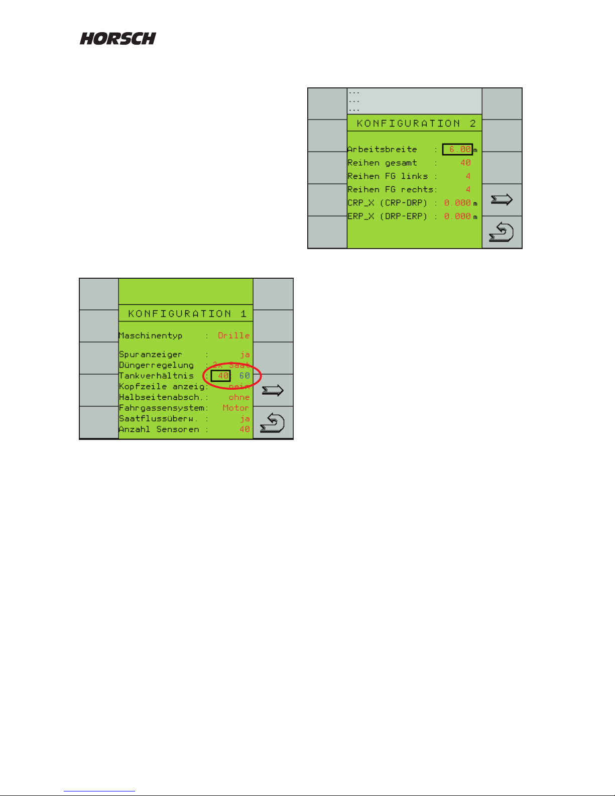
Joining of hoppers
On twin hopper machines the hopper for seed
and fertilizer can be mutually used for drilling
seed.
After choosing "2 x seed" in the fertilizer control
menu a second line "hopper ratio" will be
displayed.
Here one must enter the tank sizes relative to
one another.
After the calibration samples taken from both
metering units the computer will use these sizes
to calculate the required speeds for both motors,
to make sure that both hoppers will be empty at
the same time.
Enter the tank size ratio
Conguration 2
Working width
Enter the machine width in metres with two
decimal digits.
Total rows
Enter the number of drill coulters.
This input is required for the calculation of
quantity reduction with switched tram line.
Rows FG left
Enter the number of seed hoses in the left
machine side.
Rows FG right
Enter the number of seed hoses in the right
machine side.
Page 37
35
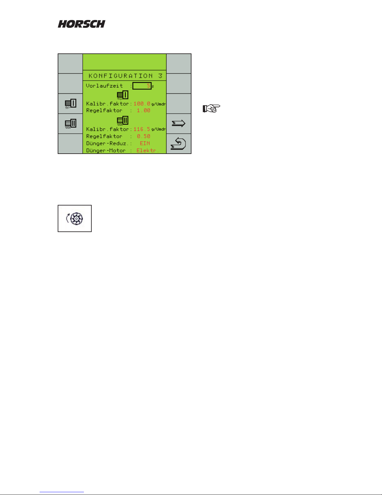
Conguration 3
Seed calibration
This menu can be used to run a seed calibration
(see seed calibration).
Prime rotor time
The rot o r ro tates as long as
specied under prime rotor time.
A setting of 5 seconds is enough to e.g. place
seed in eld corners.
If the computer receives a speed signal during
this period, the computer will take over the
control.
Calibration factor
The calibration factor value for seed and fertiliser
is used to save weight determined in the seed
calibration in gram per revolution.
The calibration factor can also be directly entered
as calibration value - see "Seed calibration direct
input".
Calibration direct input
If a seed, fertiliser or liquid fertiliser is repetitively
used, only the rst calibration must be performed,
whereby the calibration factor and the associated
rotor should be recorded.
When using the same seed, fertiliser or liquid
fertiliser again, the value can be entered directly..
Direct entry of the calibration value
should only be used for absolutely
identical seeds or fertilisers. The same
rotor should also be installed, as
otherwise a wrong quantity will be
placed.
If the machine is equipped with a liquid fertiliser
system, the calibration factor of approx.
600 pulses per litre must be entered here.
Due to the consistency dierences in liquid
fertilisers the value needs to be matched to the
actual placement quantity.
For this purpose use the first measurable
placement deviations from the nominal quantity
to calculate the percentage and change the
calibration factor by the same percentage.
The deviation is displayed in the menu bar
"performance data" (second work page with
key "i") in the calculated amount in litres to the
actually metered quantity.
If the displayed quantity is lower than that of the
actually metered quantity the calibration value
must be reduced and vice versa.
Page 38
36
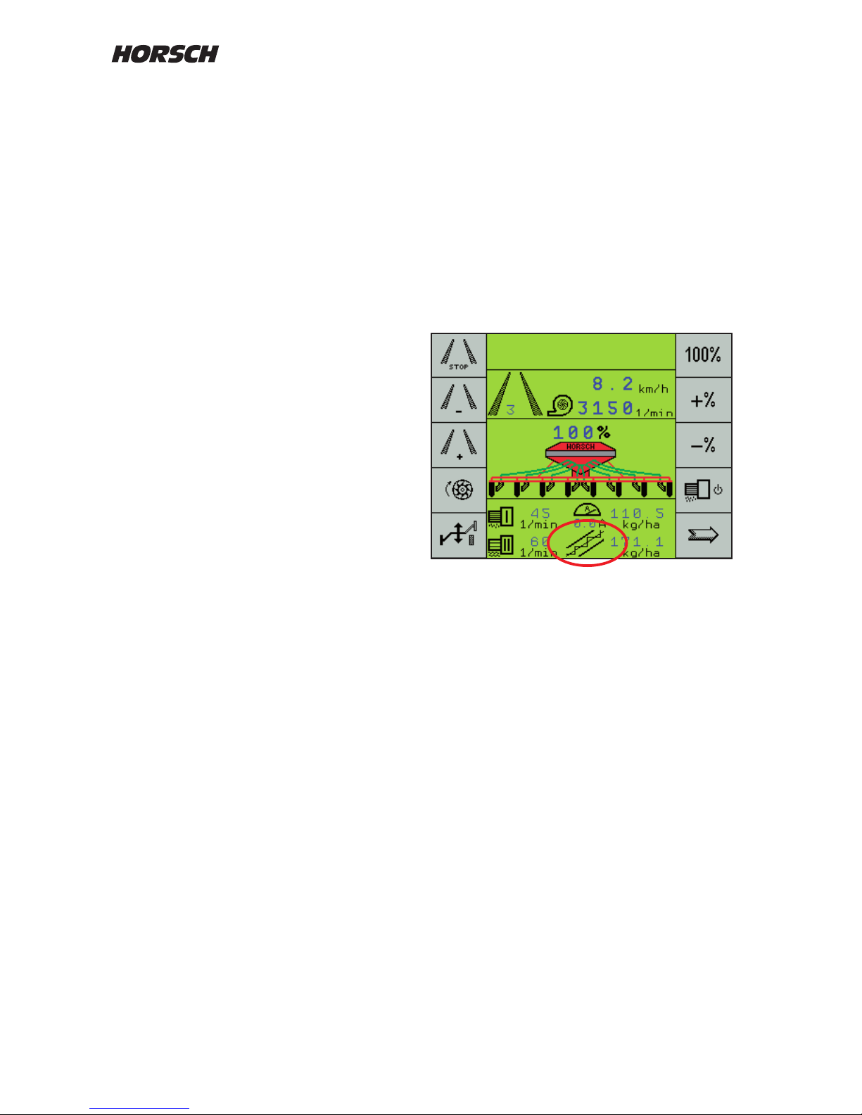
Fertiliser motor
In the fertiliser motor menu you can choose
between an "electric" and a "hydraulic" fertiliser
motor.
Normally you should choose electric. Here the
same metering drive with electric motor is used
as for seed
For some special applications, e.g. in connection
with front hopper and auger metering, which
are driven hydraulically and controlled by a
proportional valve, you must switch over to
"hydraulic".
In the work screen the hydraulic drive is displayed
as auger metering instead of the electric current
consumption. Operation, calibration etc. are
identical with the electrical drive.
Control factor
The control factors inuence various parameters,
like the computer controls the electric drive
during acceleration load change, untrue running
of the metering shaft, jammed grains or when
the nominal quantity is reached.
Based on experience made in the past the
control factor should be set between 0.5 and 1.
For "normal" seeds hardly any dierence can
be noticed in use.
With grain which have e.g. a tendency to
jamming (beans) or which may cause any other
disturbances, a change to the lower area down
to 0.1 may be benecial.
Fertiliser reduction
In case of fertiliser reduction one can determine
whether solid and liquid fertiliser quantities
should be reduced by standard for tram lines.
Page 39
37
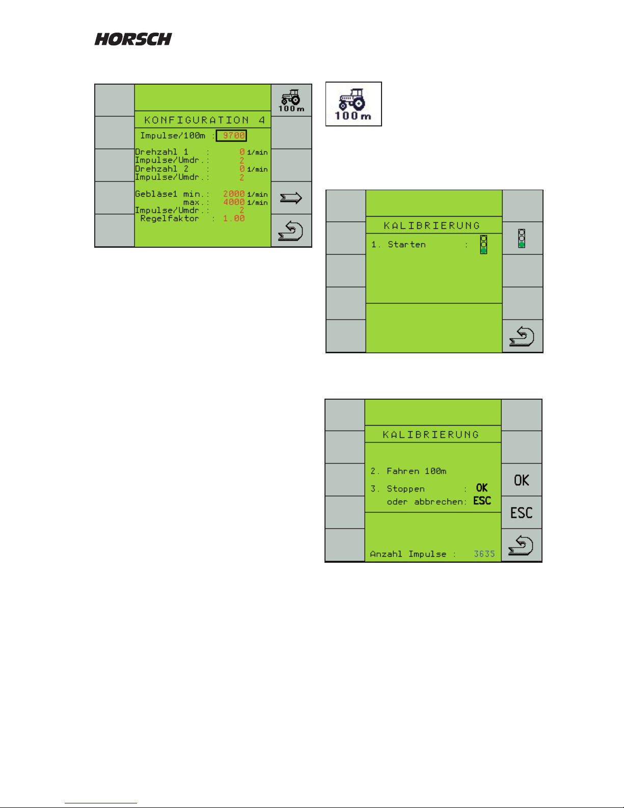
Travelling the 100 m distance
Switch over to the calibration
program.
Press the "trac light button" to start calibration.
Another menu screen will appear.
Start travelling with the tractor.
The pulses will be counted and displayed.
Stop at the 100 m mark.
Confirm the pulses (approx. 9700) with the
"OK"-key. The value will be saved and used for
all calculations.
Conguration 4
This menu page is used to enter the data for
speed, shaft monitoring and fan.
For the speed the pulses for the 100 m distance
must be entered.
The entry serves as a calculation information for
speed display, area calculation and to control
the seed and fertiliser quantity.
The number of pulses can be entered directly
(approx. 9700).
For an exact input a 100 m distance must be
travelled during initial installation and for later
checks.
Page 40

38
Shaft monitoring
The system is able to display and monitor the
speeds of two shafts.
For this purpose enter the desired minimum
speeds for both shafts with the + and - keys.
Enter the number of pulses per revolution for
both shafts.
If the minimum speed is fallen short of, an
audible and visible alarm will be emitted.
Fan monitoring
For fan monitoring the maximum speed can be
entered and monitored alongside the minimum
speed.
For the fan the number of pulses per revolution
(2) must also be entered.
When the limit values are exceeded or fallen
short of, an audible and visible alarm will be
emitted.
Control factor
The control factor has no function yet.
Page 41
39
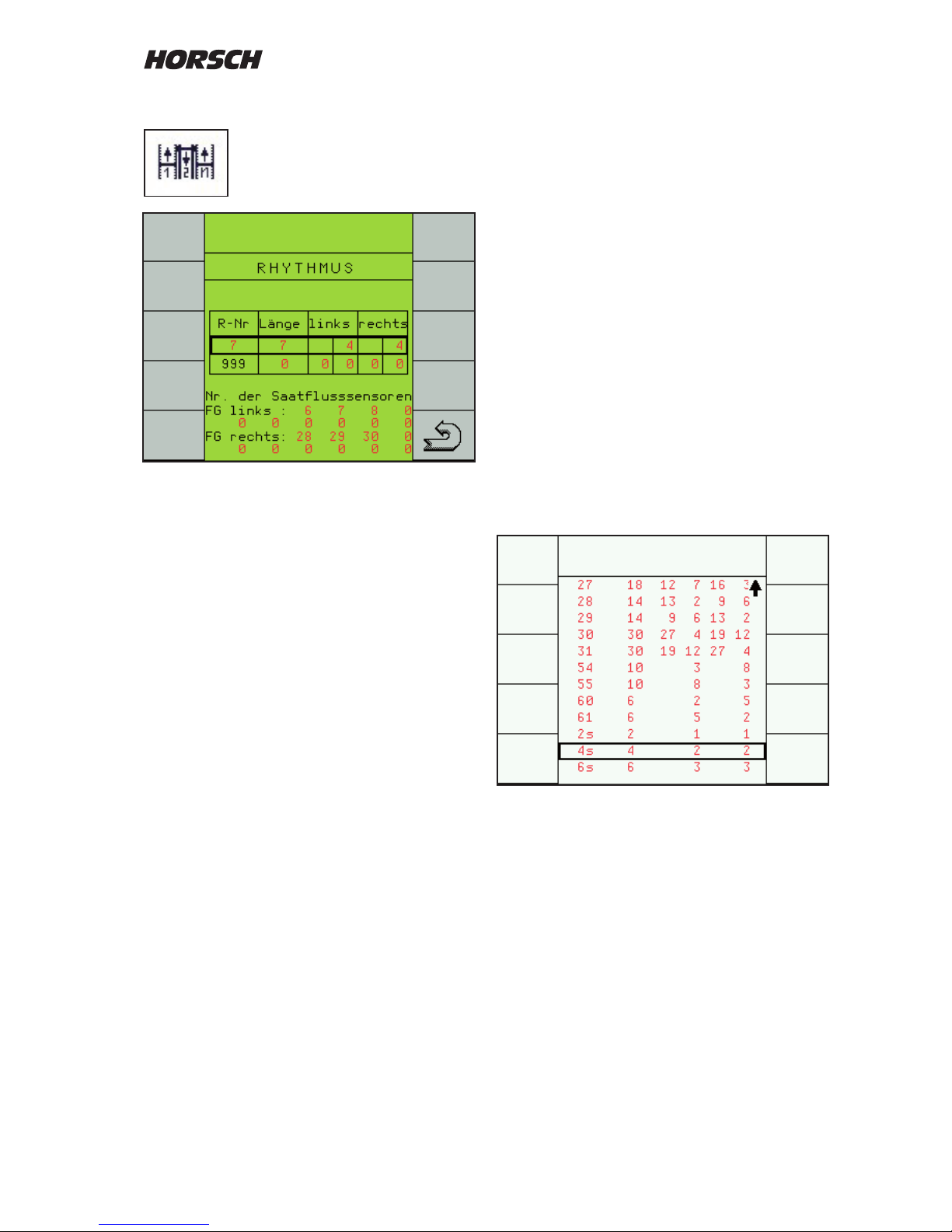
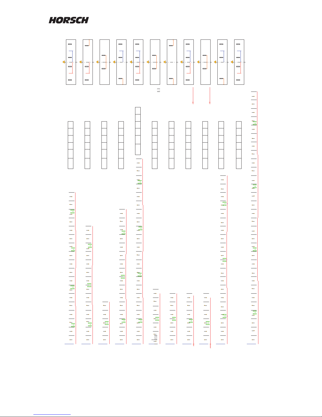
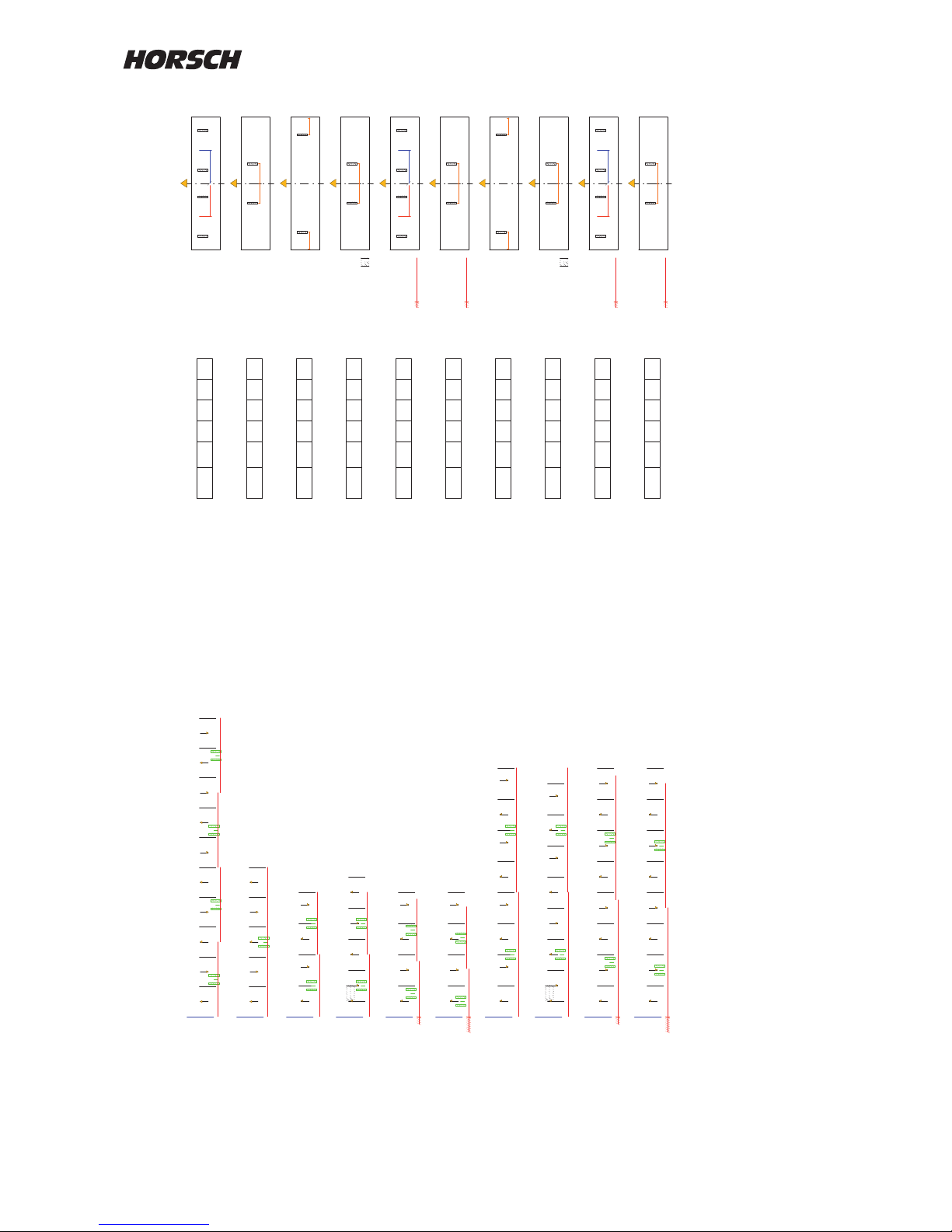
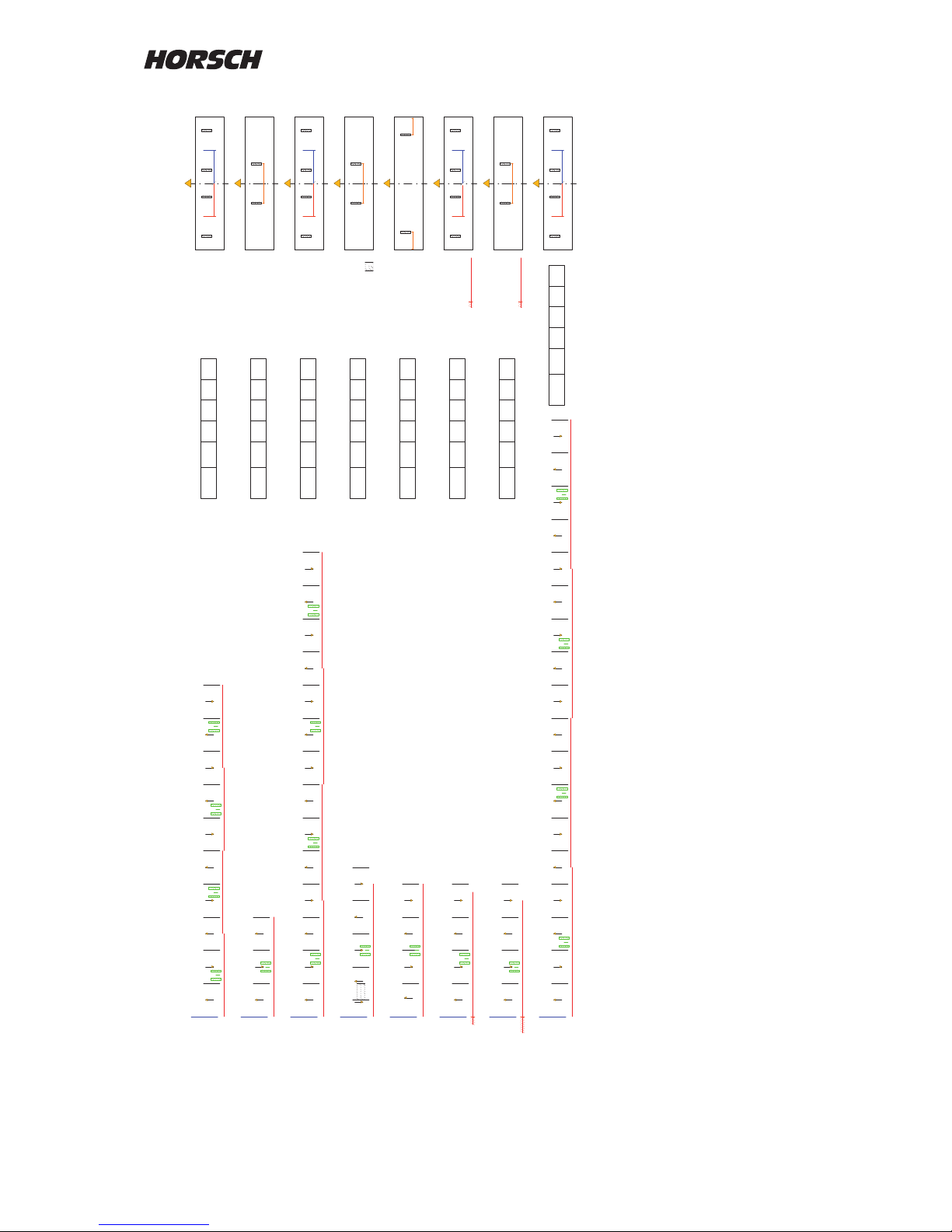
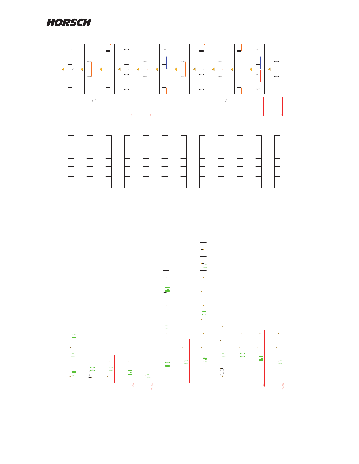
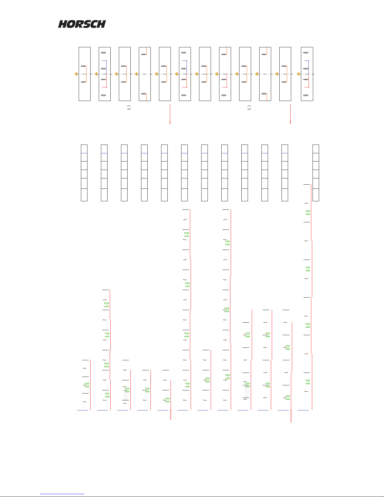
Tram line rhythm
Overview and selection of tram line
rhythm.
The "R-No" only represents the number from
the table and has no relevance for the rhythm.
The "Length" shows the number of bouts until
the rhythm repeats itself.
The elds "left" or "right" show the bout numbers
in which the seed hoses are closed.
The rhythm is determined by the width of the
drill and the working width of the care taking
machine (sprayer).
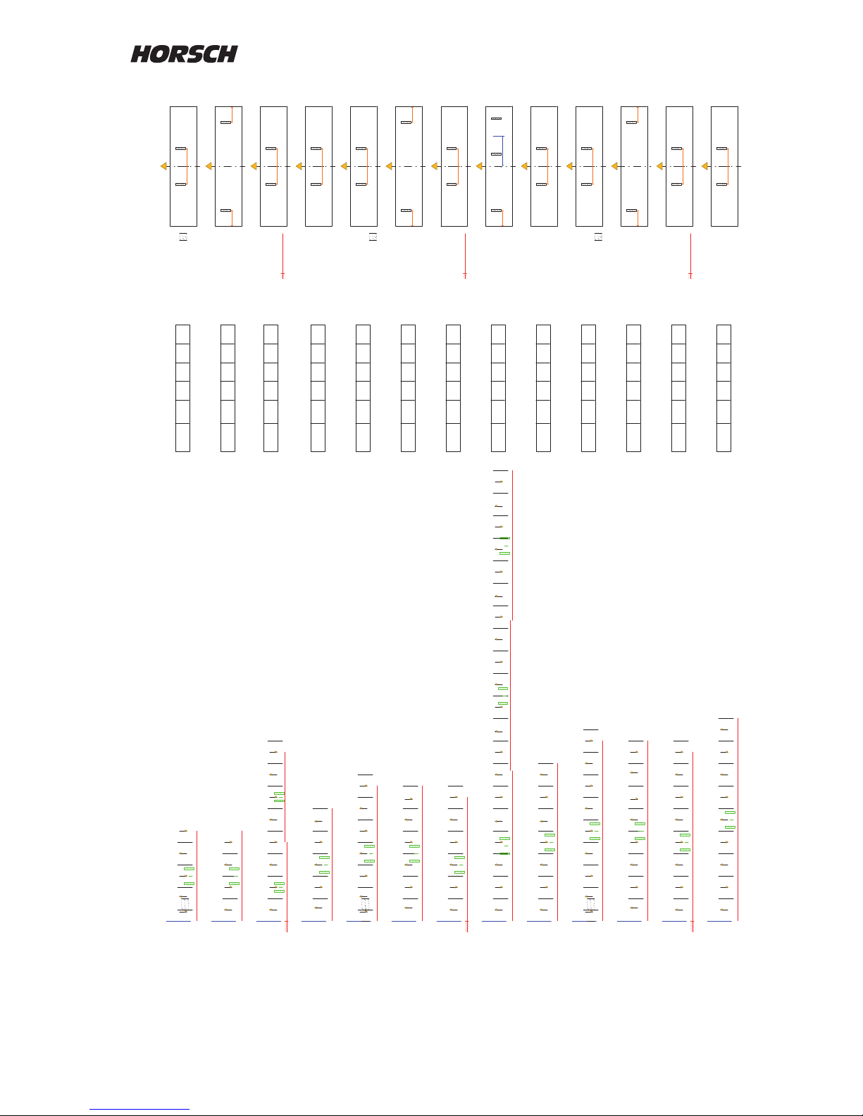
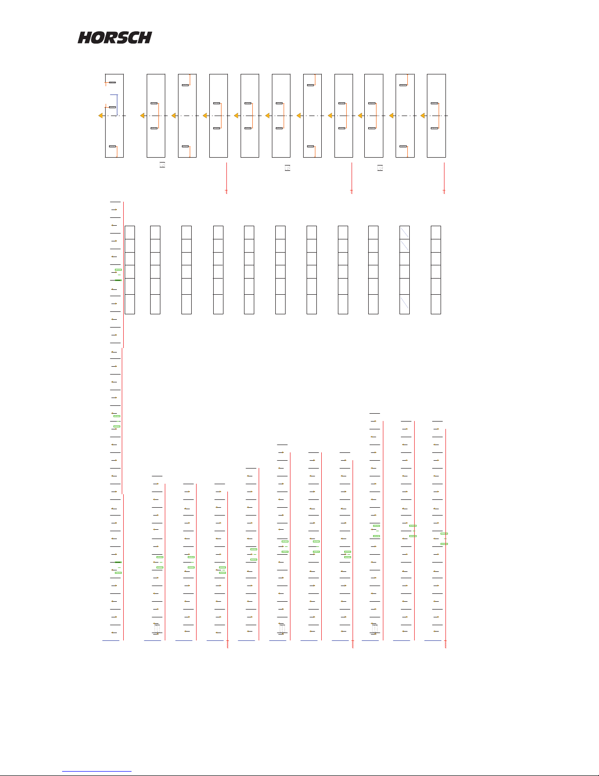
The rhythm for the corresponding combination
can be taken from the diagrams.
After selecting the rhythm number from the table
the rhythm is displayed in the rst line.
The second line with R-No. 999 can be used t
enter a freely programmable rhythm.
Selection of rhythm
Column A: Working width of drill
Column B: Working width of sprayer
Column C: Overview over the individual
drilling and spraying tracks
Column D: Rhythm input into computer
Column E: Installation position of valves in
the machine
Choose drill working width (A) and spraying
width (B) from the diagrams. Column (C) shows
the individual drill and spraying bouts with the
bout numbers for the tram line.
Column (D) shows the rhythm number and (E)
the installation position of the valves.
The rhythm numbers are stored in the computer
table for selection.
For this purpose highlight the rst line with the
+ and - keys and press "Return".
The rhythm table is displayed.
Use the + / - keys to select the rhythm number
and press "Return" to conrm.
The number is accepted and displayed in the
rst line.
Page 42
40
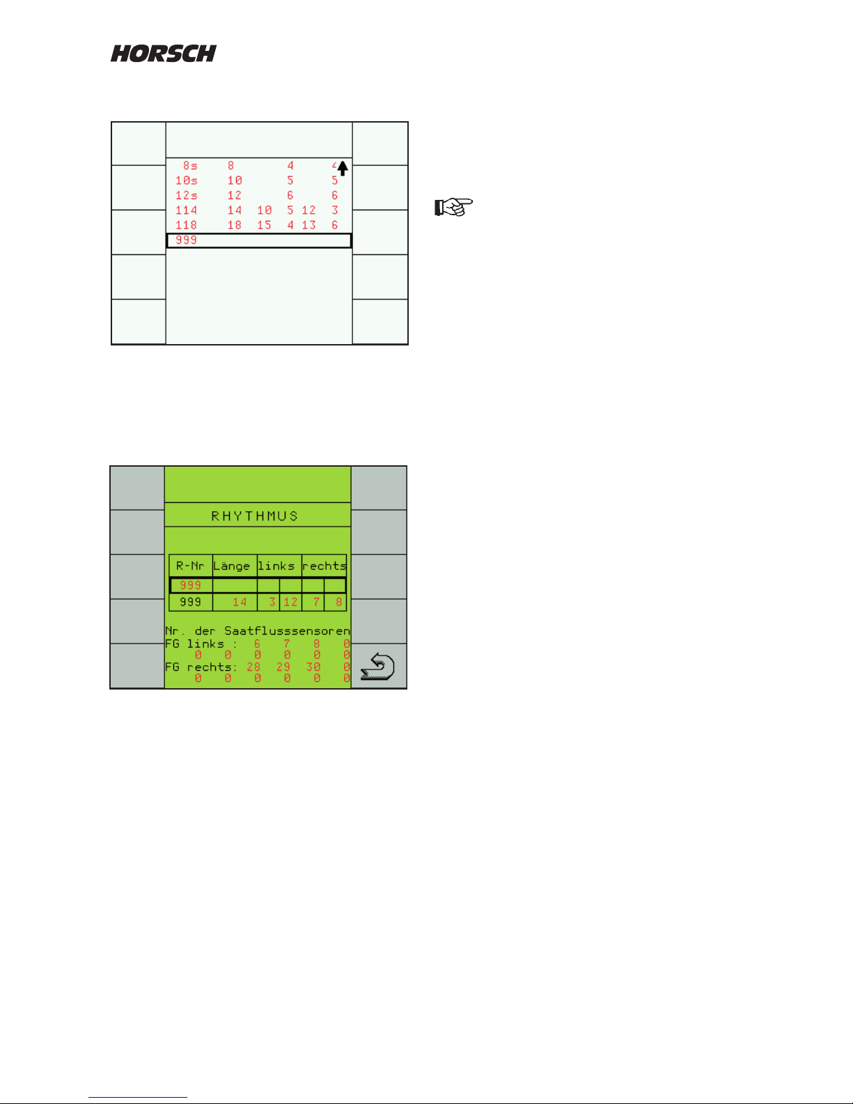
If the numbers are from the rhythm table, the
number for the next page start is the following
or one number back.
When entering 999 the numbers in the elds for
left and right must normally be interchanged.
However, one must always make sure
the the valves for the other side are
installed accordingly.
For some working width one can choose from
overdrilling with half working width, "joining
travel" or switching off of partial widths of
sprayers.
The sections that had been overdrilled are
marked shaded.
The selection of these rhythms depends on the
installation position of the valves in the machine.
Free rhythm input
Selection 999 from the computer table activates
the programmable rhythm.
Length of rhythm and bout number must be
entered into the second line.
All rhythm numbers are specied for starting
work from the left hand headland of a eld.
When star ting work fr om the right hand
headland of eld the numbers must be changed
accordingly.
Page 43
41
DatumEntw.DateinameZeichnungsnummerMaschine Zeichnung
3 12
3 12
3 15
3 18
3 18
3 20
3 21
3 24
3 24
1/2
1/2
1/2 1/2
0,5m
1/2
3 24
1,5 m
1,5 m
1,5 m
A B C ED
3 12
1,50 m
3 18
1,50 m
3 27
1,50 m
8 S
- - -2
- -2 3
- -- 3 -
- 3 -- - -
- 4- 3 - -
- 4- - - -- - -- - - - 10 11 - 17 - - -
- 4- - - - -
- - 4- - - - -
- 4- - 5 - - -
L R
1/2 1/2
L R
1/2
L R
1/2 1/2
L R
1/2 1/2
L R
1/2
L R
1/2
L R
1/2 1/2
L R
1/2 1/2
L R
1/2
- - 4- - - - -
4 S
999 4 2 3
4 2 2
5 5 3 3
6 S 6 3 3
999 6 3 4
999 20 10 11 4 17
7 7 4 4
8 S 8 4 4
999 8 4 5
8 4
- -2 -
4 S 4 2
- -- 3
6 S 6 3
- - -- 5 - - - -
L R
1/2 1/2
9 9 5 5
L R
1/2 1/2
L R
1/2 1/2
L R
1/2 1/2
4
2
- -
3
Page 44
42
DatumEntw.DateinameZeichnungsnummerMaschine Zeichnung
3 28
3 30
1/2 1/2
0,5m
1,5 m
A B C E
3 30
1/2
D
3 30
1,50 m
3 36
3 36
1/2
3 33
1,5 m
3 36
1,50 m
3 42
3 42
1/2
1,5 m
3 42
1,50 m
- - -- 5 -
- -- - 5 14- - 15- - - - - - - - - - - - -- - - 24 - -
- -- -
L R
1/2 1/2
L R
1/2
max. 2m
- -- - 5 6 - - - -
L R
1/2
999 28 14 15 5 24
10 S 10 5 5
999 10 5 6
- - -- 5 - - - -
10 S 10
5
- -- - - 6 7 - - -
- - -- - 6 - -- - - -
- -
L R
1/2 1/2
L R
1/2
- -- - - 6 - - - - -
L R
1/2 1/2
11
12 S 12 6 6
11 6 6
999 12 76
- -- - - 6 - - - - - -
12 S 12 6
5
L R
1/2 1/2
-
6
L R
1/2 1/2
- -- - - - 7 8 - -
- - -- - - 7 -- - - -
- -
L R
1/2 1/2
L R
1/2
999 14 7 7
14
14 78
- -- - - - 7 - - - - -
999 14 7
7
L R
1/2 1/2
- -
- -
8 7
999
- -
Page 45
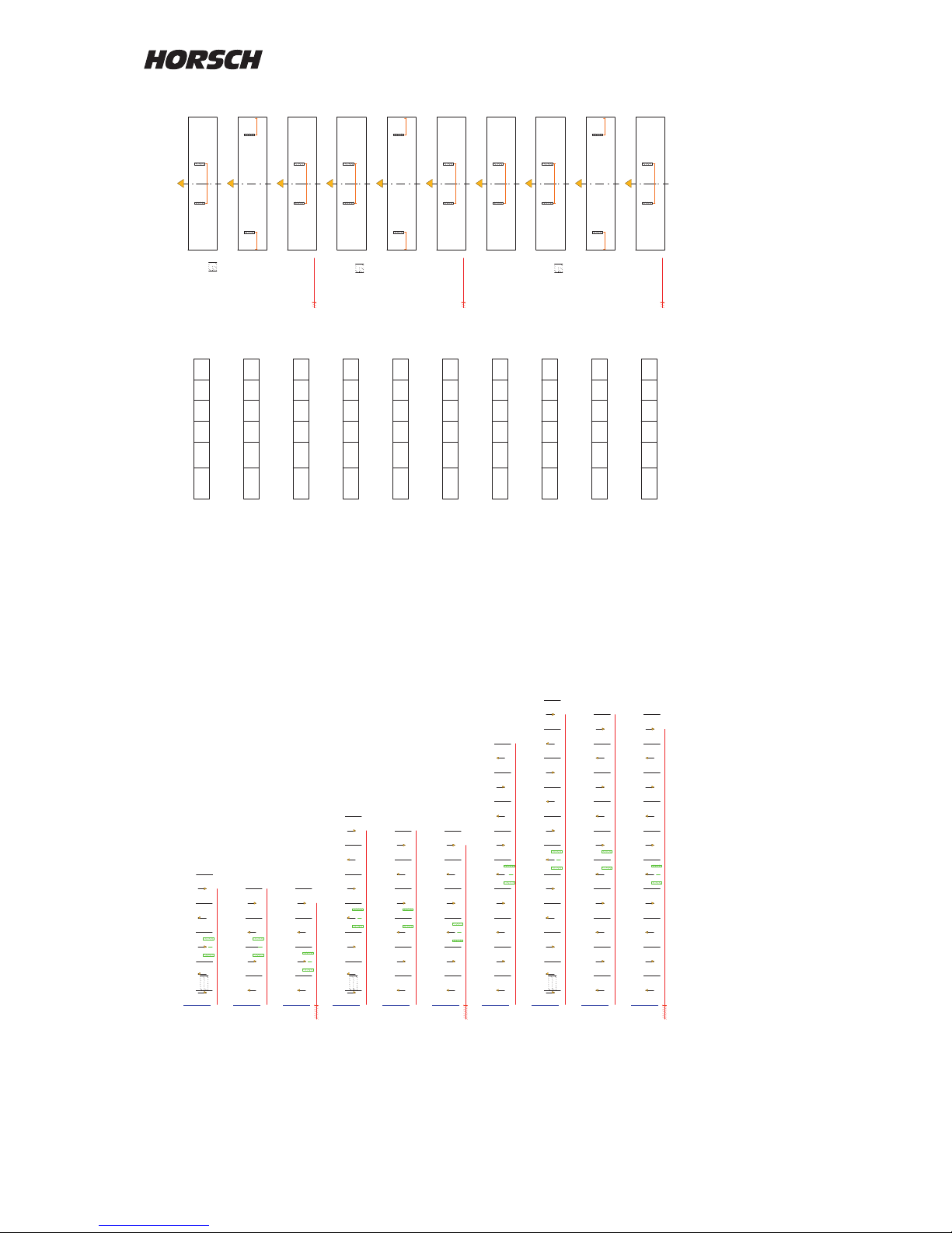
43
DatumEntw.DateinameZeichnungsnummerMaschine Zeichnung
A B C ED
3,5 14
3,5 14
3,5 14
3,5 21
1,75 m
1/2
1,75 m
3,5 21
3,5 21
1,75 m
3,5 28
3,5 35
3,5 35
3,5 35
1,75 m
1/2
1/2
1,75 m
1,75 m
-
-
2
- 2
1/2 1/2
4S 4 2 2
-
2 3 -
- 2
1/2 1/2
4 S 4 2
- -
1/2 1/2
6 S 6 3 3
- -
L R
1/2
- -
999 6 3 4
3 4 - -
- 3
-
999 4 32
-
3
- -
1/2 1/2
6 S 6 3
3 -
- -
5
- -
1/2 1/2
9 9 5
- -
5 -
-
- -
-
1/2 1/2
10 S 10 5 5
- 5
- -
999 10 5 6
- - 5 6
- - -
5
- -
1/2 1/2
10 S 10 5
- -
5 -
-
- -
-
- -
-
- -
-
-
-
L R
1/2
L R
1/2
Page 46
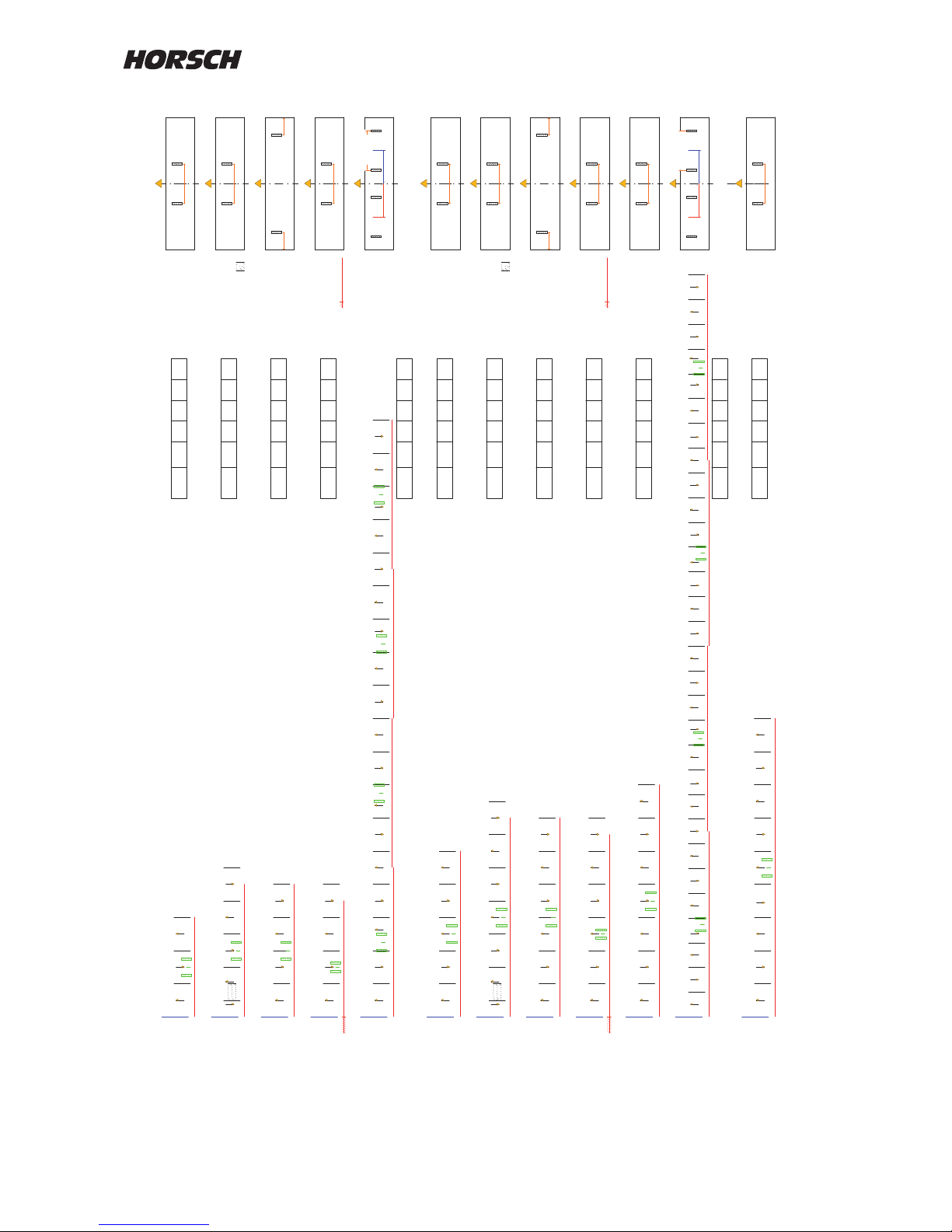
44
DatumEntw.DateinameZeichnungsnummerMaschine Zeichnung
4 12
4 16
4 16
4 20
4 24
4 24
4 28
2 m
1/2
2 m
1/2
4 18
1/2 1/2
4 30
4 36
1/2 1/2
A B C ED
4 16
2,0 m
4 24
2,0 m
- 2 -
- 2 - -
- 2 3 -
- - 3 - -
- - 3 - - -
3 4 - -
- -
- 4 - -
- -
-
L R
1/2 1/2
L R
1/2 1/2
L R
1/2
L R
1/2 1/2
L R
1/2 1/2
L R
1/2
L R
1/2 1/2
3 - - -
- - - - - 12
7 -
- 16 - -
- -
L R
1/2 1/2
1m
1m
max. 2m
- 4 - -
- -
-
- - -
-
-
12
-
-
- - 19 -
-
-
- - -
-
27
-
-
- 0
- - 5 -
- -
- - -
L R
1/2 1/2
L R
1/2 1/2
1m
1m
max. 2m
3 3 2 2
4 S 4 2 2
999 4 2 3
18 18 3 7
5 5 3 3
6 S 6 3 3
999 6 3 4
7 7 4 4
30 30 27 4 19 12
9 9 5 5
16 12
- 2 - -
4 S 4 2
max. 2,0 m
6 S 6
3 - - -
- -
3
2
L R
1/2 1/2
3
L R
1/2 1/2
Page 47
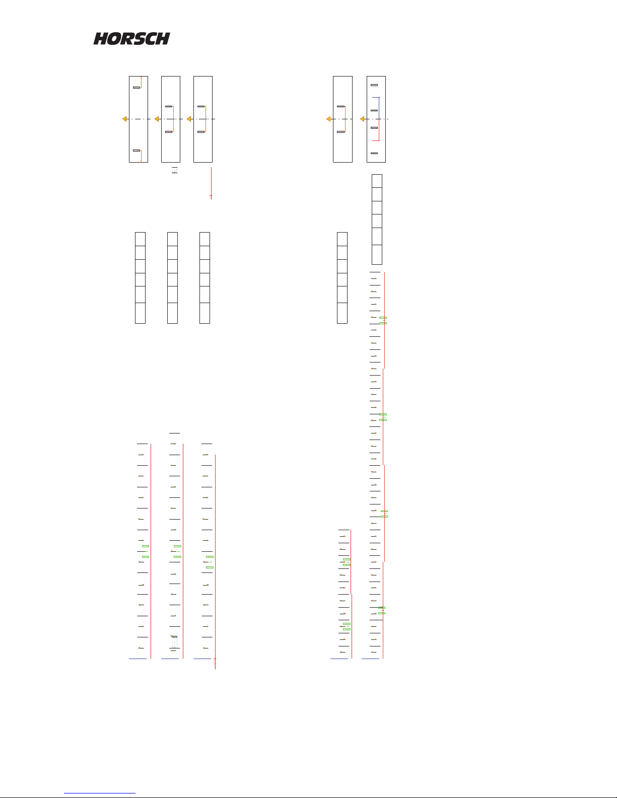
45
DatumEntw.DateinameZeichnungsnummerMaschine Zeichnung
A B C ED
4 40
1/2
4 40
2 m
4 40
2,0 m
4,80 24
4,80 36
1/2 1/2
6- - 5
- -
- - -
L R
1/2 1/2
999 10 5
-
L R
1/2
6
- - 5 -
- -
- - -
-
10 S 10 5
5
- - 5 -
- -
- - -
10 S 10 5
-
5
L R
1/2 1/2
-
5 5 33
- 3 - -
L R
1/2 1/2
4 12
19
27
L R
1/2 1/2
1,2 m
1,2 m
999 30 1912274
Page 48
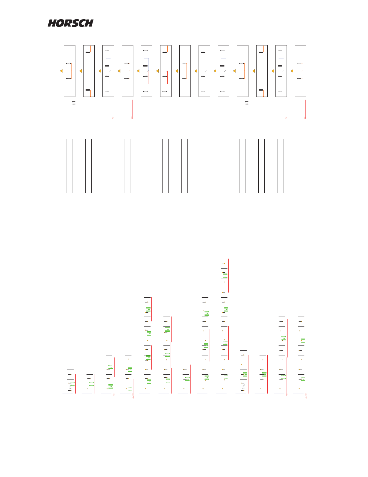
46
DatumEntw.DateinameZeichnungsnummerMaschine Zeichnung
6 15
6 18
6 20
6 21
6 24
6 24
3 m
1/2 1/2
1/2
1/2 1/2
A B C ED
6 12
6 12
3,0 m
1/2
6 16
1/2
6 12
1/2 1/2
6 24
1/2
1/2 1/2
1,5 m
1,5 m
6 12
3,0 m
6 24
3,0 m
- 2
- 2 - - - 7
9 -
4 -
- 2 -
- 2 - 5 6 - 9 -- -
- 2 - - 6 - 9 -- - - 13 --
- -
- 2 3 -
L R
1/2 1/2
L R
1/2 1/2
1,5 m
1,5 m
L R
1/2 1/2
1 m
L R
1/2 1/2
1,5 m
1,5 m
L R
1/2 1/2
16
3 3 2 2
10 4 2
20 10 2
5
28 14 2 6
4 S 4 2 2
999 4 2
9 6
7 9
13 9
L R
1/2 1/2
L R
1/2
2 S 2 1 1
999 2
2
1
1 2
1 -
- 2 - 5 - 74 -
L R
1/2 1/2
1 m
999 8 4 75 2
1 -
L R
1/2 1/2
1,5 m
1,5 m
999 2 1
- 2 - -
L R
1/2
999 4 2 3
L R
1/2 1/2
1,5 m
1,5 m
1 -
2 S 2 11
L R
1/2 1/2
4 S 4 2
- 2 - -
2
L R
1/2 1/2
Page 49
47
DatumEntw.DateinameZeichnungsnummerMaschine Zeichnung
A B C ED
6 36
6 36
3 m
1/2
6 40
1/2 1/2
1,0 m
6 33
1/2 1/2
1,5 m
1/2 1/2
6 36
1/2 1/2
1,5 m
1/2 1/2
1,5 m
6 27
6 28
1/2 1/2
1/2
6 36
3,0 m
6 32
1/2 1/2
1,0 m
6 30
6 45
1/2 1/2
- - 3 --
- - 3 -4
-
-
L R
1/2 1/2
L R
1/2
6 S 6 3 3
999 6 3 4
- 4- - - -- - -- - - - 10 11 - 17 - - -
L R
1/2
999 20 10 11 4 17
- - 3 -- - - 9 -- - - 14 - -- - ---- 20
L R
1,5 m
999
22
9
2014 3
- - 3 -- -
999 6 3
L R
1,5 m
- - 3 - - 7 - -- - 12 -- - - - -16
- - 3 - - 7 - -- 8 12 -- -
L R
1/2 1/2
1,5 m
1,5 m
L R
1/2 1/2
1 m
26
999 14 12 8
18 3 716 12
3 7
- - 3 -- -
6 S 6 3
3
L R
1/2 1/2
- - 3 - - - 9 -- 8 - -- 14
24 16 8 39 14
L R
1/2
- - 3 --
5 5 33
L R
1/2 1/2
L R
1/2 1/2
1,5 m
1,5 m
30 30 4 1227 19
-- - - - -
- -
4 - - 12 - - -- -- - 19 - -
- -
- - 27 - - -
Page 50
48
DatumEntw.DateinameZeichnungsnummerMaschine Zeichnung
A B C E
1/2
3,75 m
3,75 m
1/2
7,5 15
7,5 15
7,5 30
7,5 30
D
7,5 15
1/2 1/2
1,875 m
1/2 1/2
1,875 m
7,5 30
1/2 1/2
1,875 m
1/2 1/2
1,875 m
7,5 15
3,75 m
7,5 30
3,75 m
1/2 1/2
1,80 m
1/2 1/2
L R
1/2 1/2
L R
1/2 1/2
L R
1/2
L R
1/2
1
1
- 2 3 -
- 2 -
999
2 S 2 1 1
2
999 4 2
4 S 4 2 2
3
1
1
999 2
-
1
L R
1,875 m
- 2 - -
999 4 2
L R
1,875 m
1
2 S 2
-
1
2
2
1
L R
1/2 1/2
- 2 - -
4 S 4 2
2
L R
1/2 1/2
7,2 36
5 5 3 3
L R
1/2 1/2
7,2 18
-
16 10
2
4 2
-
4 - - 7 - 9 -
7 9
L R
1,80 m
- - 3 - -
Page 51
49
DatumEntw.DateinameZeichnungsnummerMaschine Zeichnung
8 20
8 24
8 28
1/2 1/2
1/2 1/2
A B C ED
8 32
8 32
8 36
4 m
1/2
1/2 1/2
8 32
1/2 1/2
2,0 m
1/2 1/2
2,0 m
8 32
4,0 m
- 2 - - 7 --4 9 -
- 2 -
- 2 - - - -6- 9 - - - 13 -
L R
1/2 1/2
2m
2m
L R
1/2 1/2
L R
1/2 1/2
2m
2m
16
3 3 2 2
10 4 2
28 14 2
6
13 9
7 9
- 2 - -
- 2 3 -
- - 3 - - - 7 - - 12- - - - 16 -
-
-
L R
1/2 1/2
L R
1/2
L R
1/2 1/2
2m
2m
4 S 4 2 2
999 4 23
26 18 3
7
16 12
- 2 - -
999 4 2
L R
2,0 m
- 2 - -
4 S 4 2
2
L R
1/2 1/2
Page 52
50
DatumEntw.DateinameZeichnungsnummerMaschine Zeichnung
9 18
9 18
9 27
9 36
9 36
9 30
4,5 m
1/2
1/2
4,5 m
1/2
9 12
1/2 1/2
1,5m
9 24
1/2 1/2
1,5m
A B C ED
9 18
1/2 1/2
2,25 m
1/2 1/2
2,25 m
9 36
1/2 1/2
2,25 m
1/2 1/2
2,25 m
9 36
4,5 m
9 18
4,5 m
-
1 -
1 2
-
- 2
-
- 2
-
- 5 6 - - 9 -
2
-
-
- 2
3
-
L R
1/2 1/2
L R
1/2
L R
1/2 1/2
L R
1/2 1/2
1,5m
L R
1/2 1/2
L R
1/2
1 2
3
4
L R
1/2
- 2
-
4 5 - 7 -
L R
1/2
999
2 S 2 1 1
4 2 4
999 2
2
999 8 4 7
1
3 1
3
20 10 2 5
3 2 2
999 4 2
5 2
9 6
4 S 4 2 2
3
L R
1
999 2
1
L R
2,25 m
- 2
-
-
999 4 2
L R
2,25 m
- 2
-
-
4 S 4 2
-1
2 S 2
1
1
L R
1/2 1/2
2
L R
1/2 1/2
Page 53
51
12 18
12 24
12 24
12 30
12 36
DatumEntw.DateinameZeichnungsnummerMaschine Zeichnung
1/2 1/2
3m
6 m
1/2
1/2 1/2
3m
12 40
1/2
A B C ED
10 30
12 24
6,0 m
1/2 1/2
4,5m
18 27
15 30
15 30
7,5 m
1/2
7,5 m
15 30
1 - 3 4 - 6
1 -
1 2
- 2 - 4 - -
7 - 9 -
- 2 -
L R
1/2 1/2
3m
L R
1/2 1/2
L R
1/2
L R
1/2 1/2
3m
L R
1/2 1/2
- 2 - - 5 6 - - 9 -
L R
1/2 1/2
2m
22
2 S 2 1 1
6 3 1
999 2
2
16 10 4 2
3 3 2 2
20 10 9 2 6 5
1
4 6
7 9
- 2 -
L R
3 3 2 2
1/2 1/2
1 -
2 S 2 1
1
L R
1/2 1/2
1 3- 4 6-
L R
1/2 1/2
4,5m
999 6 4
6
3 1
1 - 1
2S 2 1 1
1
999
2 1
2 1 2
L R
1/2 1/2
L R
1/2
1
2S
2 1 1
- 1 -
2
L R
1/2 1/2
Page 54
52
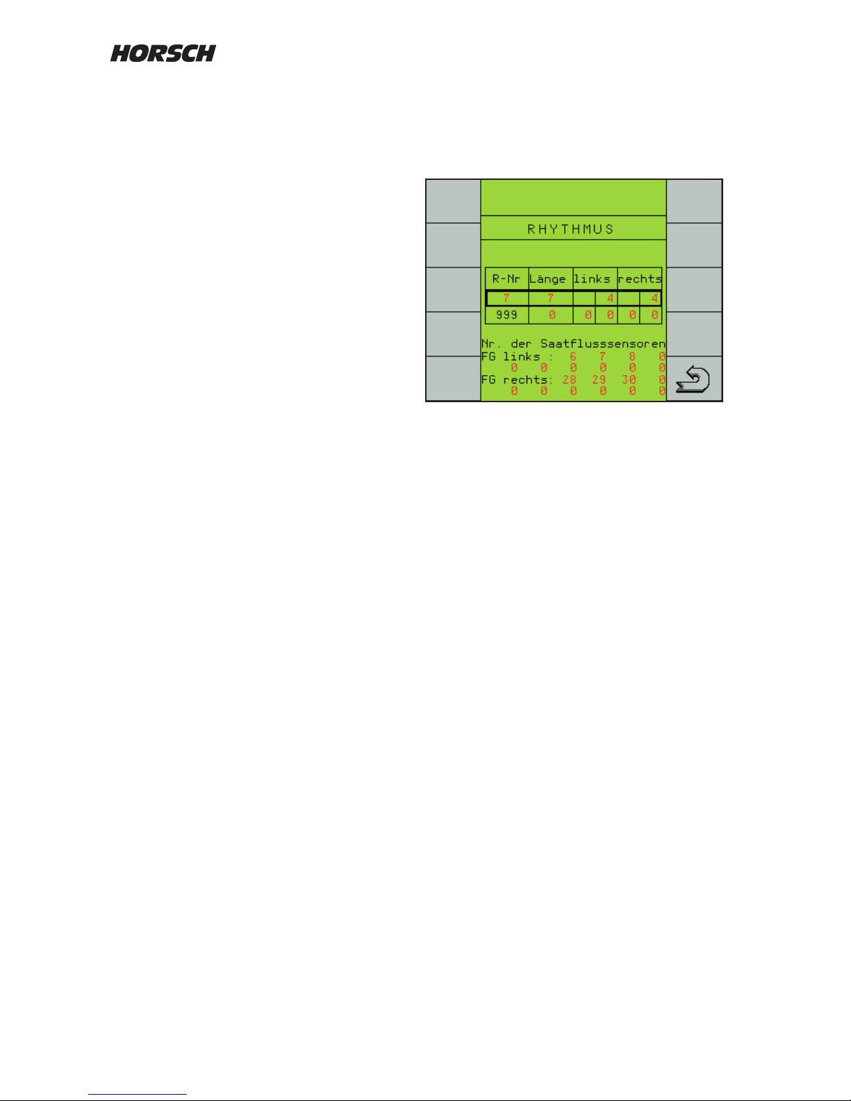
Entering sensor numbers for FGS
If the seed hoses of the tram line tracks are
equipped with seed ow sensors, these must be
removed from monitoring if tram line is switched.
The input possibility for this appears as soon
as the seed ow monitoring in the machine
conguration is switched on.
Use the + / - keys to select the tram line left and
the tram line right and enter the numbers of the
seed ow sensors.
Ten seed ow sensors, which are not to be
monitored when the tram line is switched, can
be entered for each bout.
If, with a tram line switched on, seed or fertiliser
drops through the hose because of a defective
or not closed valve, the sensor will detect this
and report it as a fault "Seed ow in xx".
Seed ow monitoring
The system consists of a seed ow module, the
sensors in the seed lines and the wiring.
The monitoring system may also be installed
later.
The module is connected to the Y-cable of the
computer. Up to 120 sensors can be installed
in the seed lines.
The seed flow monitoring system submits
an alarm in case of blocked seed hoses and
quantity changes, but also if seed or fertiliser
drops through when a bout is switched.
The seed ow system must be switched on in
the machine conguration and the number of
sensors entered before starting.
The number of seed flow sensors must be
entered in the menu of trams line rhythms.
Monitoring becomes active as soon as the
sensitivity is set to 1 or higher.
Page 55
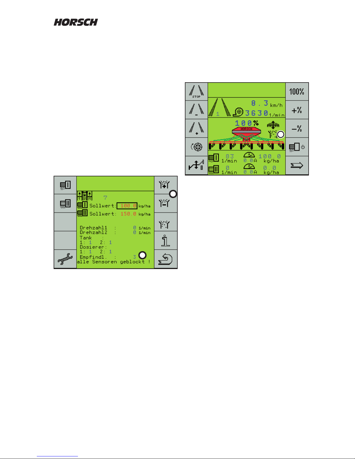
53
Setting the sensitivity
On the third page the sensitivity can be set with
the + and - keys (1) in 10 steps.
The setting depends on grain size, type and
quantity of seed.
Setting
The setting must be made during seeding and
at normal working speed.
The sensitivity is thereby matched to the seed
quantity. Deviations are indicated by means of
an alarm.
During sowing regulate the sensitivity (2) up with
the + key (1), until the rst sensors are reported
blocked.
Then reduce the sensitivity, until no blockage
is reported.
Normally 1 to 2 stages back are sucient. The
further you regulate down, the more quantity
deviations will be accepted, until the alarm will
respond.
Seed ow monitoring
Seed ow monitoring is switched on as soon as
the sensitivity is set to 1 or higher.
The display of the rst work page shows the
seed ow monitoring with the symbol (3).
During sowing the symbol is permanently visible.
If the work signal fails, e.g. when turning and no
grains are blown through, the symbol will ash.
On the third page all sensors will then be
reported as blocked.
1
2
3
Page 56
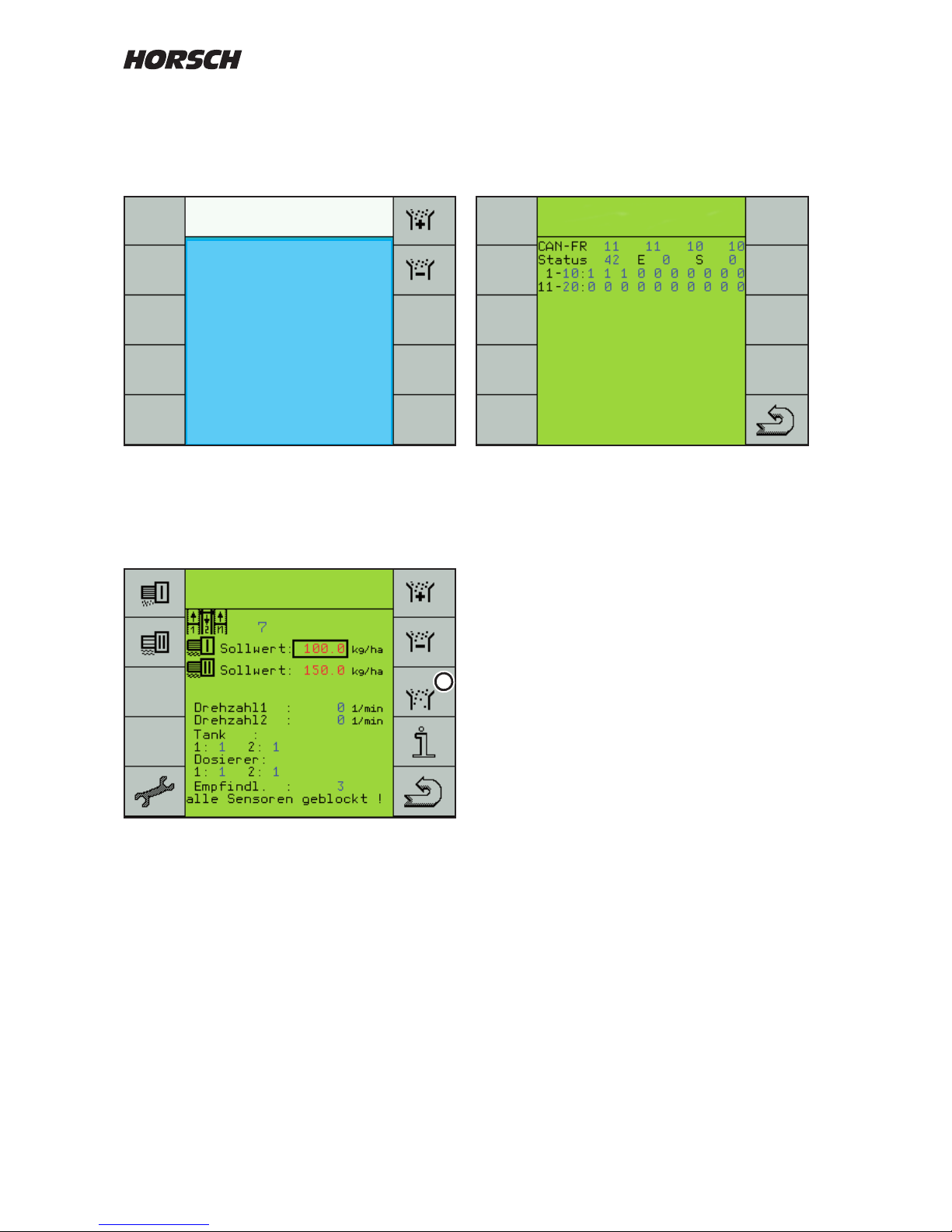
54
Seed ow diagnose
The seed ow diagnose indicates the blocked
sensors, but also defective sensors or broken
cables.
In the rst line the "CAN-Frames" and in the
second line the status is counted. As long
as these continue to count the monitoring is
functioning.
At "E" the type of fault is displayed, a cable
breakage or blockage with "1". The number
"9" appears when the system attempts to reestablish the connection.
At "S" the last functioning sensor is indicated.
The fault or broken cable must be located after
this sensor.
The bottom section shows the operating status
of each sensor. The gure 1 represents each
sensor without fault. Blocked sensors are
indicated with "0".
After correcting a fault it will take up to 1 minute
until the current operating status is displayed
again.
Alarm message
In case of blockage or quantity deviations the
message "No seed ow at sensor XX" will be
displayed.
If several hoses are blocked only the rst number
of the blocked hoses will be indicated in the
alarm.
The other numbers of blocked hoses are
displayed on the third work page.
Key (4) can be used to switch into the seed ow
system for trouble shooting.
No
seed ow
sensor 3
4
Page 57
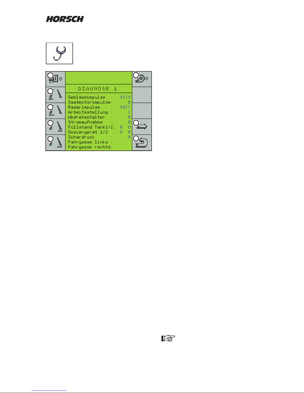
55
Diagnostics program
In the diagnostics program the input
and output signals can be tested.
1. Button seed metering motor
The seed metering motor runs until the key
is pressed again. The display shows and
successively counts the seed motor pulses.
2. Button tramline left ON
The wings for the left hand tram line must
close and the display changes the left tram
line indication to "ON".
3. Button tramline left OFF
The wings for the left hand tram line must
open and the display changes the left tram
line indication to "OFF".
4. Button tramline right ON
The wings for the right hand tram line must
close and the display changes the right tram
line indication to "ON".
5. Button tramline right OFF
The wings for the right hand tram line must
open and the display changes the right tram
line indication to "OFF".
6. No function
7. Continue to next diagnostics page.
8. Back to the machine data selection
Fan pulses
When the fan is runn ing th e puls es ar e
continuously counted.
Radar pulses
During travel the radar pulses are successively
counted.
Work position
Here the work signal of the hydraulic pressure
switch can be checked. With the machine
lowered "0" must be indicated, in lifted condition
the display changes to 1.
Calibration switch
Normal indication "0", when turning off the
display changes to 1.
Current consumption
Shows the present current consumption.
Filling level hopper 1 / 2 (seed hopper)
Indicates the switching condition of the hopper
sensors. With an empty hopper the display
changes from 0 to 1.
The number of hopp ers is automat ically
displayed when selecting the "fertiliser control"
option in the menu "machine conguration".
The sensors inside the hopper can be adjusted
in three height steps. The height should be
chosen in such a way, that one can still drive to
the end of the eld when the alarm "Hopper X
empty" is emitted.
Filling level metering unit 1 / 2
Indicates the switching condition of the sensors
in the metering unit. The sensors monitor
bridging in the seed hopper and warn in case
of an empty metering unit.
In case of an alar m eliminate the caus e
immediately, as otherwise there will be empty
spots in the seed bed.
Coulter pressure
On machines with coulter pressure adjustment
and optional equipment for automatic seed
quantity adjustment you can here check the
function of the hydraulic pressure switch.
Use the arrow key (7) to switch to the
second diagnostics page.
6
7
2
3
4
5
1
8
Page 58

56
The second page in the diagnostics system is
displayed.
Here one can check the functions of the metering
drive for the fertiliser hopper, the hydraulic bout
marker control with lifting hydraulics and the
extension for the wing hydraulics as well as
the half width control and the pre emergence
markers.
The hydraulic functions (2 - 5) are shown at the
bottom of the display when current is switched on.
1. Button fertiliser metering motor
The fertiliser metering motor runs until the
key is pressed again. The display shows
and successively counts the fertiliser motor
pulses.
2. Bout marker left
The key switches current to the hydraulic
valve for left hand bout marker.
3. Bout marker right
The key switches current to the hydraulic
valve for right hand bout marker.
4. Machine "Lift" The key
switches current to both solenoid valves for
the lifting hydraulics.
5. Machine "Fold" The key
switches current to both solenoid valves for
the the machine's wing hydraulics.
6. Button for half width control right
The servo motor moves as long as the key is
held depressed or until the next limit switch
is reached.
7. Button for half width control left
The servo motor moves as long as the key is
held depressed or until the next limit switch
is reached.
8. Key for pre emergence markers:
When pressing the key current is applied to
both cables of the boutmarkers.
9. Arrow keys to third page "Diagnostics".
10. Return to work page.
With the arrow key (9) you open the page
"Diagnostics 3". Here the total performance of
the machine is displayed.
These data cannot be deleted!
The key (10) can be used to select machine
data.
The mhx-version shows the software status in
the computer, e.g. 8.52.
On machines with two computers, both software
states are displayed. The software states should
be identical.
Dierent software combinations can lead to
problems.
1
1. Delete Pool (CE)
This button deletes the log (pool) in the
terminal. After pressing this button, the
system will restart.
Th e te rmi nal in this case fetches the
data, graphics for the screen and also the
language from the computer.
A restart may become necessary after a
malfunction, when changing the language
or in case of program changes.
4
3
5
2
8
10
6
7
9
1
Page 59
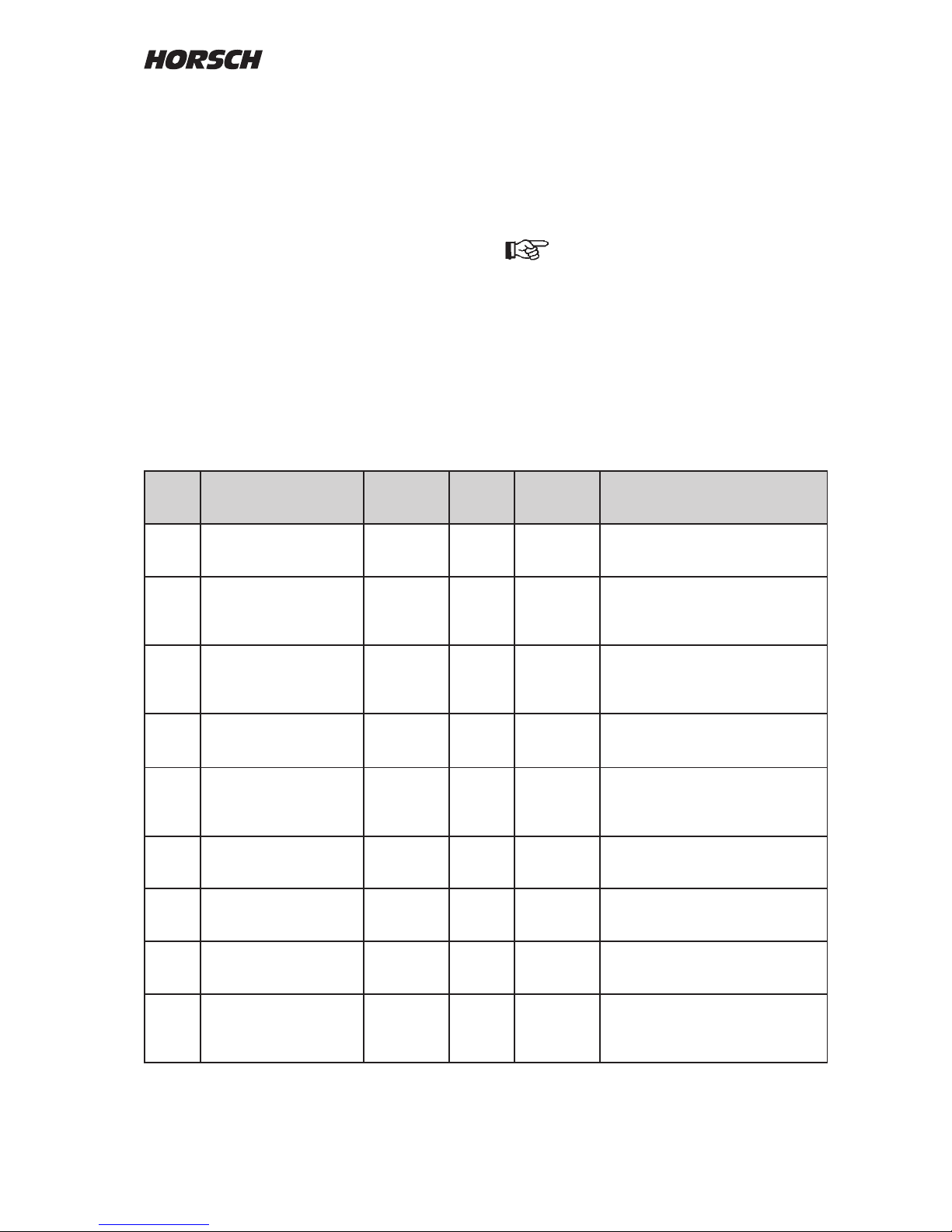
57
Alarm messages
Alarm
No.
Alarm text Alarm after
(sec.)
Con-
rmation
required
Alarm
repeat
(sec.)
Remedy
01 - 02
33 - 35
37
Motor (1 - 4) stopped immediately yes immediately Stop immediately and rectify cause
03 - 04
36
38
Motor (1 - 4) overheated immediately yes immediately Here the computer is monitored.
Stop immediately and rectify cause
of overheating - allow the computer
to cool down.
05 - 06 Machine computer (1 - 2)
failed
5 yes 60 Check cable connection between
monitor and computers.
Delete program in monitor and
reload.
07 - 08
39 - 40
Overload motor (1 - 4)
switched o
immediately immediately Once the current draw exceeds
approx. 16 A, stop and eliminate the
cause for this high current draw.
09 - 10
41 - 42
Current draw too high
motor (1 - 4)
60 10 Once the current consumption is
above 11 A for one minute, rectify
the cause for the hard moving
metering drive.
11 - 13 No signal position left
No signal position middle
No signal position right
10 10 If the signals for half width control
cannot be detected, check sensor or
switch position.
14 - 15
45 - 46
Motor (1 - 4) outside
control range
immediately 5 Keep changing the working speed,
until the motor is back in the control
range (15 - 150 rpm).
16 - 17
47 - 54
Setpoint for seed or
fertiliser cannot be
maintained
15 15 Once the set value is exceeded or
fallen short of by 10%, match the
working speed or change the rotor.
18 Seed ow system fault
sensor xx
immediately yes 15 In case of defective sensors or cable
breakage normally the last intact
sensor is displayed. The fault is
located after this sensor.
Alarm overview
All important system functions are monitored by
the computer and alarm messages are displayed
when limit values are exceeded or fallen short of.
There are default alarm messages like e.g.
"Hopper empty" and alarm messages, which
can be set by the operator like e.g. "min. and
max. fan speed".
Some alarm messages need to be conrmed,
others keep repeating, until the limit value is no
longer exceeded.
In case of malfunctions, which could damage
components (e.g. "Motor x overloaded") or if the
metering drive has failed ("Motor x stopped"),
the alarm is triggered without delay. It keeps
repeating, until the machine is stopped and the
cause of the fault is eliminated.
When lifting out the machine at the
headland all exis ting alar ms atre
aut omat ically ackn owled ged an d
re activat ed when the machine is
lowered again in the ground.
Page 60

58
Alarm
No.
Alarm text Alarm after
(sec.)
Con-
rmation
required
Alarm
repeat
(sec.)
Remedy
19 - 20
48 - 49
Fan speed (1 -2)
exceeded/fallen short of
5 15 Return the fan speed to the limit
range or match the fan alarm speed
accordingly.
21 - 22 Fan speed (1 2)
exceeded/fallen short of
1 15 Check the shaft monitoring for
Maistro or rotary cross harrow.
Check the shaft drive.
23 Seed ow monitoring
system failed
10 60 Check the cable connection to the
seed ow module.
Check the seed ow module.
24 Seed ow in tram line xx 8 8 No grains should fall out when the
tram line gate is closed. Check the
function and leak tightness of the
gate.
Check whether the sensor number
has been entered into the FSG
menu.
25 No seed ow sensor xx 8 8 Check the seed hose no. xx for
blockage.
Check the function of the sensor.
26 - 29 Filling level (hopper 1 - 4)
fallen short of
5 yes The hopper (1 - 4) runs empty. The
alarm will only become active again
after the hopper has been lled.
30 - 32
55 -56
Motor (1 - 4) speed too
high
5 yes 5 The alarm will be displayed above
135 rpm. Filling the cells is no
longer assured for all types of seed.
Reduce the working speed.
install a bigger rotor.
43 - 44 Double placement in row
No placement in row
8 8 When sowing single grains (Maistro):
Check working speed, metering unit,
setting and seed.
50 - 53 Metering unit (1 - 4)
empty
5 yes 10 Monitoring of bridging in hopper.
Metering unit (1 - 4) empty. Stop
immediately, no seed or fertiliser
is sown.
Sporadic failure of work
signal.
<2 The alarm appears in case of short
interruption (< 2 seconds) of the
work signal. Check oating position
of hydraulics, switch for work signal
and speed signal.
 Loading...