

horsch AutoLine Operating Instructions Manual
TRANSLATION OF THE ORIGINAL OPERATING INSTRUCTIONS
READ CAREFULLY PRIOR TO STARTING UP!
KEEP OPERATING INSTRUCTIONS IN A SAFE PLACE!
ART.:
ISSUE:
OPERATING INSTRUCTIONS
02
17
08/2018
8066
AutoLine


- Translation of the Original Operating Instructions -
Machine Identication
The corresponding data is to be entered into the list below upon
receiving the machine:
Serial number: ..................................................
Machine type: ...................................................
Year of construction: ........................................
Initial installation: ..............................................
Fittings: .............................................................
..........................................................................
..........................................................................
..........................................................................
Publication date of Operation Manual:
Latest change:
Address of Retailer: Name: ......................................................................
Road: ......................................................................
Town/City: ......................................................................
Tel.: ......................................................................
Customer No.:
Retailer: ......................................................................
Address of HORSCH: HORSCH Maschinen GmbH
92421 Schwandorf, Sitzenhof 1
92401 Schwandorf, Postbox 1038
Tel.: +49 (0) 9431 / 7143-0
Fax: +49 (0) 9431 / 7143-9200
E-mail: info@horsch.com
Customer No.:
HORSCH: ......................................................................
Conrmation of receipt of machinery
Warranty claims become only eective when the rst use of the machine is reported to HORSCH
Maschinen GmbH within a week.
At www.horsch.com under SERVICE PARTNERBEREICH an interactive PDF form is available for down-
load for this purpose (not available in all languages).
By clicking on Send – depending on the email program installed – a mail draft with the completed
form is generated automatically. Alternatively, the form can be sent as email attachment to machine.
registration@horsch.com.
A dierent form of registration (postal mail, by fax, etc.) is not allowed for.
en
02
08/2018
AutoLine
8066 17

Table of contents
Introduction ...................................................4
Prerequisites ................................................4
Operation .......................................................4
E-Manager conguration ................................4
Conguration TRACK Leader II ......................8
Activating AutoLine ......................................8
Starting AutoLine .........................................9
Changing the AutoLine working mode .......10
Move tram lines to another pass ................10
Inverting AB track for tram lines ................. 11
System boundaries ....................................12
Error codes .................................................14
Legend..........................................................14
Alarm screens...............................................15
2

3
Introduction
AutoLine is a system for the track-independent
creation of tram lines with GPS.
The tram lines are not controlled via the working
signal of the machine as with conventional tram
line control, but via GPS.
This eliminates the need for connecting tram
lines, so that beds can be created and workows
improved.
After creating the rst track lead track (AB track /
contour track), all tram lines are automatically
calculated by HORSCH AutoLine.
Whenever the drill enters a track containing a
tram line, the corresponding tram line valves
are actuated.
The function can be used in conjunction with
HORSCH Touch Terminals from software
version 02.20.11 and the E-Manager software
version 10.09.
This requires the TramLine Management license.
Prerequisites
• HORSCH Terminal Touch
Software version 02.20.11
• Job computer E-Manager Midi
Software version 10.09
• GPS
(RTK quality recommended)
• Licence Tramline Management
• Licence TRACK Leader II
Operation
Settings must also be made in the E-Manager
and the terminal itself.
E-Manager conguration
¾ Follow the operating instructions for the
E-Manager to access the Conguration menu.
CONFIGURATION
show header : yes
JD Split-Screen : no
TC Multi-Product : no
Drill depth adj. : no
AutoLine : yes
Interruption : on lift out
coult.press.set : no
Power harrow : no
¾ Select the Yes option under the AutoLine item.
¾ Access the screen for setting the tram line
rhythms; follow the operating instructions for
the E-Manager:
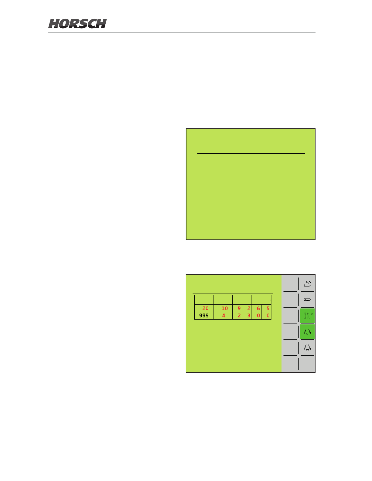
RHYTHM
R-No lgth left right
drilling in tramline .: OFF
dril
20
m
free 20
m
¾ Select the tram line rhythm according to the
working width of the drill and the crop protection machine; follow the operating instructions
for the E-Manager.
4
The pre-emergence markers are controlled with this softkey.
If the softkey is shaded green, the
pre-emergence markers are lowered
when the tram line is activated.
If the softkey is shaded grey, the
pre-emergence markers remain in the
top position if the tram line is activated.
The tram line function can be enabled or
disabled with this softkey.
With this softkey the settings for GPS-controlled tram lines are accessed.
Softkey for activating/deactivating the
track recording function in the TaskController. If the function is activated,
the middle of the tram line for the crop
protection machine is recorded in the
TRACK Leader and shown in yellow.
Accessing the next page.
The following page is not available in the Cong-
uration menu but is accessed via the GPS softkey
in the Tram line control menu:
CONFIGURATION
1 1 no
2 1 no
3 1 no
4 1 no
5 1 no
6 1 no
7 1 no
8 1 left
9 1 no
10 1 no
1 2 3
1. Number of coulter
2. Number of section
Machines without half-width shut-o have
one section. Machines with half-width shut-
o have two sections (left side of machine
- Section 1, right side of machine - Section 2).
3. Tram line valves
This species whether a tram line valve is
installed on the respective coulter.
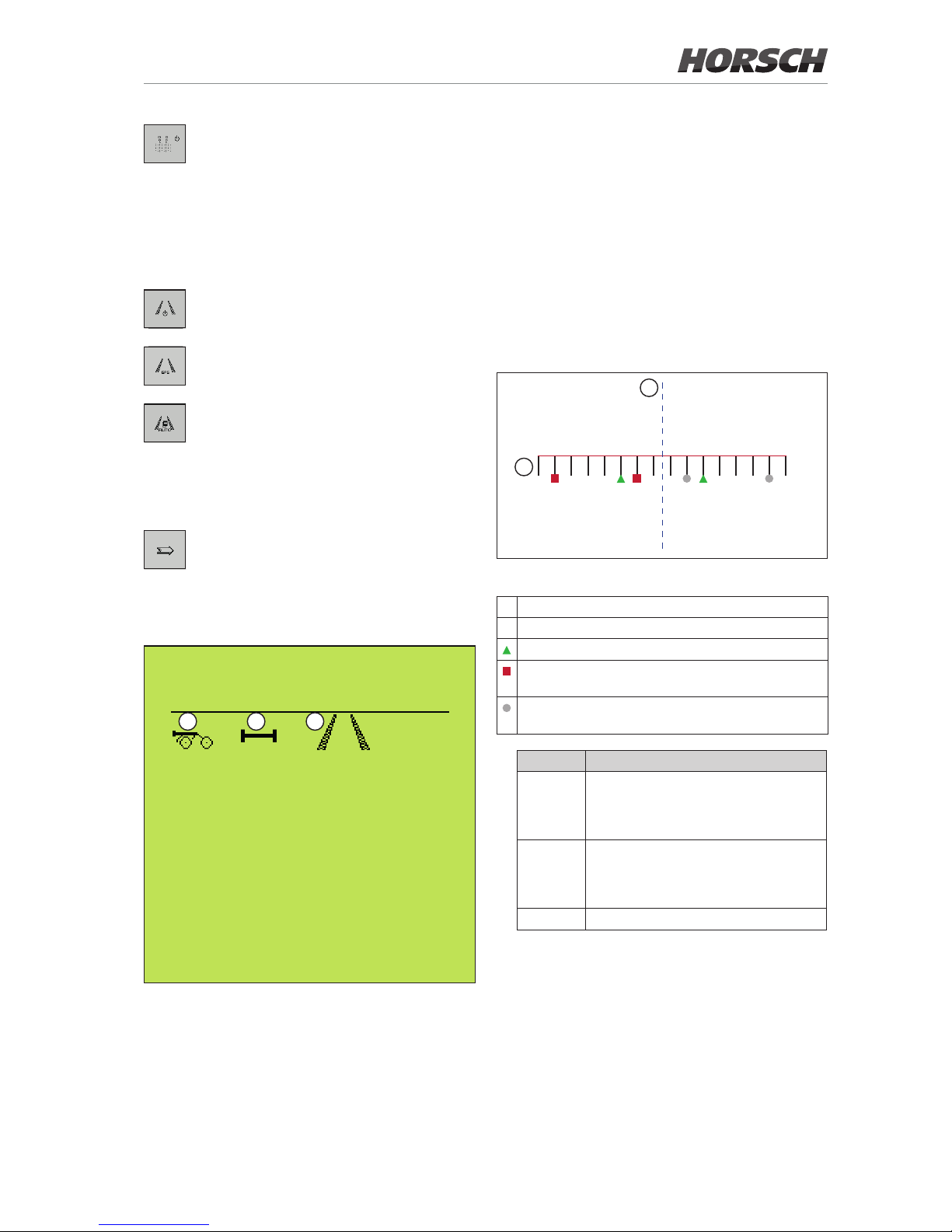
The following illustration shows the schematic
structure of a drill with dierently arranged
tram line valves.
A
B
1 2 3 4 5 6 7 8 161514131211109
Valves for creating tram lines in two passes are not
shown.
A Middle of the machine
B Seed bar with coulters
Tram line valves, symmetric
Tram line valves, asymmetric, left in direction of
travel.
Tram line valves, asymmetric, right in direction of
travel.
Option Meaning
left Tram line valve available for left
track of the crop protection machine;
clamped on left selection channel.
(In the example: Coulters 2, 6, 10)
right Tram line valve available for right
track of the crop protection machine;
clamped on right selection channel.
(In the example: Coulters 7, 11, 16)
no No tram line valve available.
5
 Loading...