

Page 1
TRANSLATION OF THE ORIGINAL OPERATING INSTRUCTIONS
READ CAREFULLY PRIOR TO STARTING UP!
KEEP OPERATING INSTRUCTIONS IN A SAFE PLACE!
ART.:
ISSUE:
OPERATING INSTRUCTIONS
02
17
12/2017
8072
AutoForce
Page 2

Page 3

- Translation of the Original Operating Instructions -
Machine Identication
The corresponding data is to be entered into the list below upon
receiving the machine:
Serial number: ..................................................
Machine type: ...................................................
Year of construction: ........................................
Initial installation: ..............................................
Fittings: .............................................................
..........................................................................
..........................................................................
..........................................................................
Publication date of Operation Manual:
Latest change:
Address of Retailer: Name: ......................................................................
Road: ......................................................................
Town/City: ......................................................................
Tel.: ......................................................................
Customer No.:
Retailer: ......................................................................
Address of HORSCH: HORSCH Maschinen GmbH
92421 Schwandorf, Sitzenhof 1
92401 Schwandorf, Postbox 1038
Tel.: +49 (0) 9431 / 7143-0
Fax: +49 (0) 9431 / 7143-9200
E-mail: [email protected]
Customer No.:
HORSCH: ......................................................................
Conrmation of receipt of machinery
Warranty claims become only eective when the rst use of the machine is reported to HORSCH
Maschinen GmbH within a week.
At www.horsch.com under SERVICE PARTNERBEREICH an interactive PDF form is available for down-
load for this purpose (not available in all languages).
By clicking on Send – depending on the email program installed – a mail draft with the completed
form is generated automatically. Alternatively, the form can be sent as email attachment to machine.
[email protected].
A dierent form of registration (postal mail, by fax, etc.) is not allowed for.
en
02
12/2017
AutoForce
8072 17
Page 4

Table of contents
AutoForce ......................................................4
Introduction .....................................................4
Checks before starting work ...........................4
Coulter unit ..................................................4
Cams ...........................................................4
Functional principle .....................................5
Forces on the drill unit ....................................5
Operation .......................................................7
AutoForce screen ...........................................7
Manual mode ..................................................7
Maestro RC manual mode..............................8
Automatic mode..............................................8
Automatic mode work screen .........................9
Manual mode work screen ...........................10
Conguration ................................................10
Settings.........................................................11
Section selection ........................................ 11
Sensor row allocation ................................ 11
Section to row allocation ............................12
Calibrating (Teach) the sensors ................. 13
Diagnostics ...................................................14
Maestro 16/18 SW (row spacing > 60 cm) ..14
Maestro 24/36/47/48 SW with
E-Manager software 10.07 ........................14
Maestro CC / RC - 12/18 SW ....................14
Delta Step coulter pressure .......................15
Additional key ............................................15
Water hole mode .......................................16
Error codes ................................................18
Troubleshooting ............................................21
Index ............................................................24
2
Page 5

3
Page 6
NOTE
These operating instructions are only valid in
combination with the E-Manager Midi 10.07 or
higher operating manual.
This document only describes the function of the
AutoForce automatic coulter pressure control.
¾ Always follow the operating instructions for
drill and E-Manager to ensure safe operation
of the machine.
AutoForce
Introduction
AutoForce is a system for the automatic coulter
pressure adjustment on the Maestro.
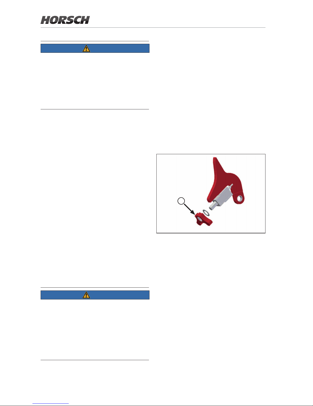
A cam with a sensor is attached to the axle of
the depth guide wheel. The sensor determines
the force acting from the ground on the depth
guide wheel.
The objective is keeping the contact force between depth guide wheel and ground constant,
regardless of the soil conditions.
As a result, the coulter unit adapts to dierent
soil conditions to ensure consistent placement
depth.
The systems may have a single or multi-section
design. For systems with one section springs are
attached to the drill unit in the track.
For systems with several sections, the respective last section is reserved for the track. Springs
can be retrotted.
NOTE
The user is responsible for the quality of sowing
in spite of the AutoForce automatic coulter pressure control.
¾ Check the quality of sowing and placement
depth in the eld several times a day.
¾ Check the calibration values of the sensors
several times a day. Observe the section
Calibration (teach) of sensors.
Checks before starting
work
Coulter unit
¾ Observe the basic setting of the coulter unit
to ensure the function of AutoForce.
¾ Adjust the parallelograms of the units hori-
zontally.
¾ With the Maestro 16/24/36 SW check the
setting of the coulter rail in addition.
¾ Observe the operating instructions of the
respective machine.
Cams
A
Sensors with cams (A)
¾ Check cams for wear.
Unequal wear of cams causes dierent placement depths.
¾ Replace the cams if necessary.
4
Page 7
Functional principle
Forces on the drill unit
A
B
C
D
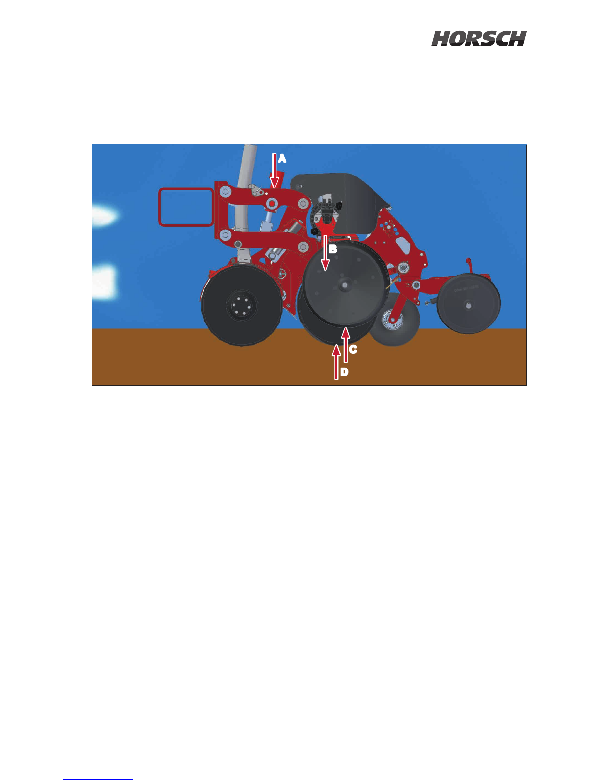
Forces on the drill unit
A hydraulic coulter pressure
B force of the drill unit’s weight
C force between soil and depth guide wheel (target value)
D Force between soil and coulter discs
The target value for the control of the coulter pressure is the force between the soil and the depth
guide wheel (C).
On soft soils, the force of the weight is sucient for the coulter discs to penetrate the soil.
On hard soils, the force between soil and the coulter discs (D) increases. As a result, the force (C)
between the soil and depth guide wheel becomes smaller. The target value is therefore undercut.
The coulter pressure (A) must now be increased hydraulically for the force (C) between soil and
depth guide wheels to correspond to the target value again and the placement depth to remain
constant.
5
Page 8
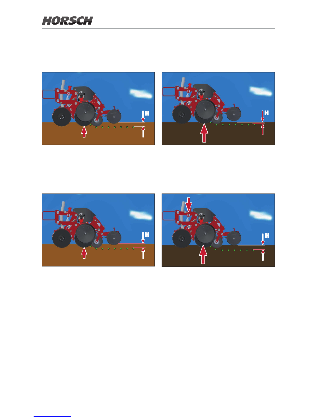
For greater clarity, the presentation of the weight force and the force between soil and depth guide
wheel is omitted on the following illustrations.
Maestro without AutoForce
H
H
Sowing on soft, moist or light soil
Placement depth H is maintained. The force
acting from the soil on the coulter discs is
relatively low.
Sowing on hard soil, clod-type soil or rocky soil
The force acting on the coulter discs increases.
The placement depth decreases.
Maestro with AutoForce
H
H
Sowing on soft, moist or light soil
Placement depth H is maintained. The force
acting from the soil on the coulter discs is
relatively low.
Sowing on hard soil, clod-type soil or rocky soil
Additional coulter pressure is hydraulically
applied to the drill unit to allow deeper penetration of the soil.
Placement depth H remains consistent.
6
Page 9
Operation
AutoForce screen
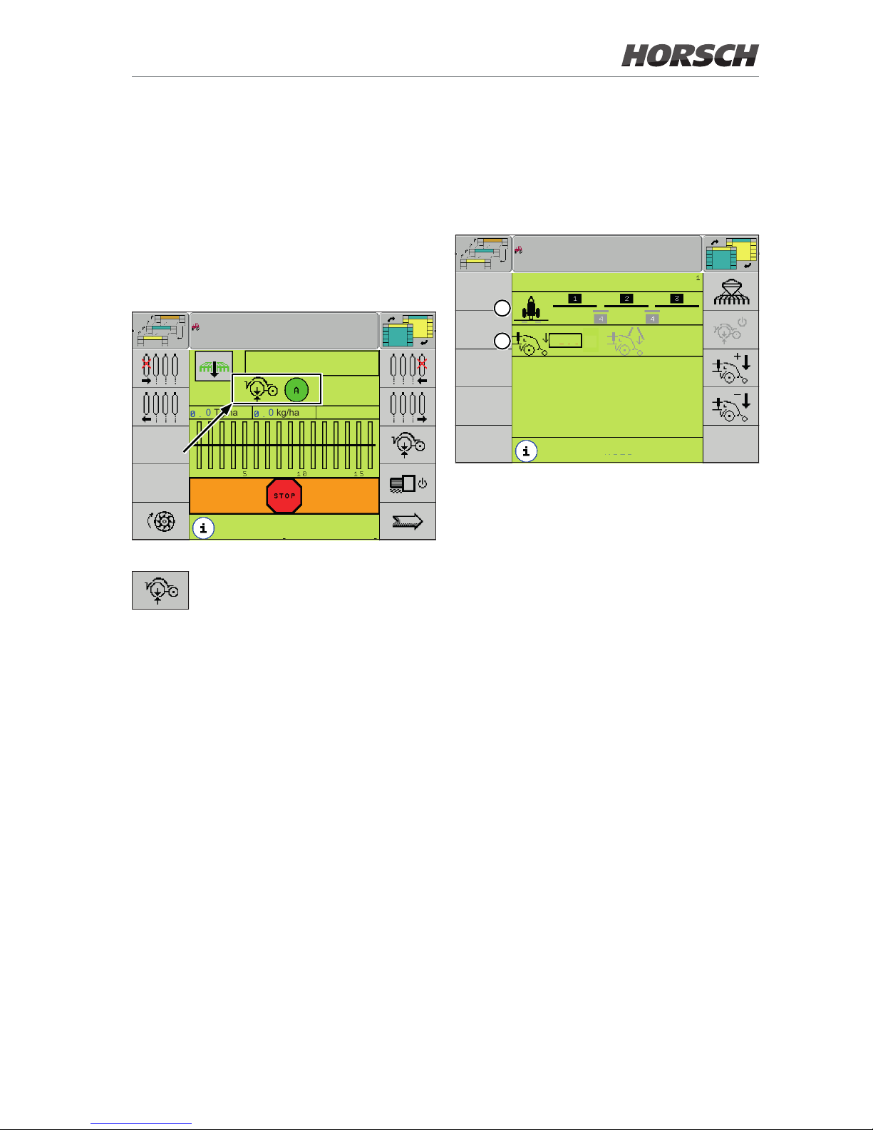
The AutoForce screen can be accessed via the
corresponding button on the working screen or
the additional key.
Depending on the terminal, the button can be
selected by rotary wheel or touch.
0.0
km/h
0 Tg/ha 0 kg/ha
maize
Working screen - Button to access the AutoForce screen
Softkey for accessing the AutoForce
screen.
Manual mode
The manual mode is active is the automatic
mode is disabled.
The manual mode must be used if no control
is possible.
AutoForce
200
kg
200
kg
Manual
res. 30.0
ha
16689
m
1
2
AutoForce screen - manual mode
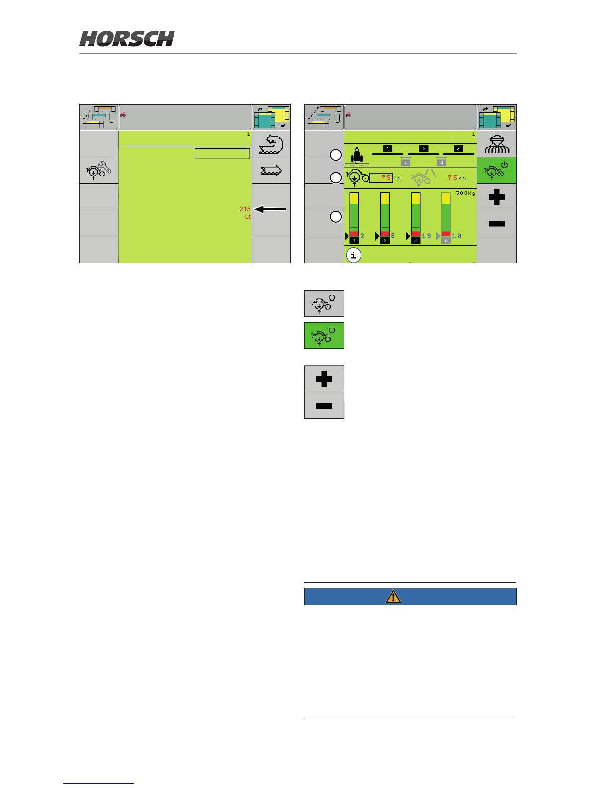
1. The diagram shows the layout of the sections.
The standard sections are shown in black,
the sections in the tracks in grey.
2. The target values for the standard sections
(black) and the sections in the tracks (grey)
can be entered here.
The hydraulic valve is then pressurised with
a constant value.
Target value range for manual mode:
150 - 350 kg.
7
Page 10
Maestro RC manual mode
CONFIGURATION
Machine : Maestro RC
Additional hopper : no
cent.hopper SOD : no
Hydraulic valve block : Track
coult.press.set : Hyd Auto
max.coult.pres : 215
Metering unit 1: without
Metering unit 2: without
fertiliser monitoring : no
Detail view : no
Maestro RC conguration
For the Maestro RC solo with 3-point attachment the maximum coulter pressure is limited
to 215 kg. The limit value can be adjusted under
max. coulter pressure.
Automatic mode
AutoForce
No
calculation of residual quantity
1
2
3
AutoForce screen - Automatic mode
Softkey for switching the automatic
mode on and o.
Softkey for changing the coulter pressure target value.
1. The diagram shows the layout of the sections.
The standard sections are shown in black,
the sections in the tracks in grey.
2. In the centre area of the display target values
for the force between the depth guide wheels
and the soil for standard sections (black) and
sections in the tracks (grey) can be entered.
¾ For systems with more than one section, set
the target value in the tracks higher than in
the standard sections.
Target value range for automatic mode:
50 - 100 kg.
NOTE
The target values must be determined in the
eld.
¾ Check the quality of sowing and placement
depth in the eld several times and daily in
case of dierent soil conditions.
¾ Correct the values for the coulter pressure
as required.
8
Page 11
3. The lower area of the display shows bar
graphs for one installed and congured section each.
Only the average value is displayed if all actual values (values of the individual sensors and
their average value) are in the green range.
A grey arrow for the respective value and
the associated row number is displayed in
addition if at least one value lies outside the
green range.
Automatic mode work
screen
0.0
km/h
0 Tg/ha 0 kg/ha
maize
Work screen
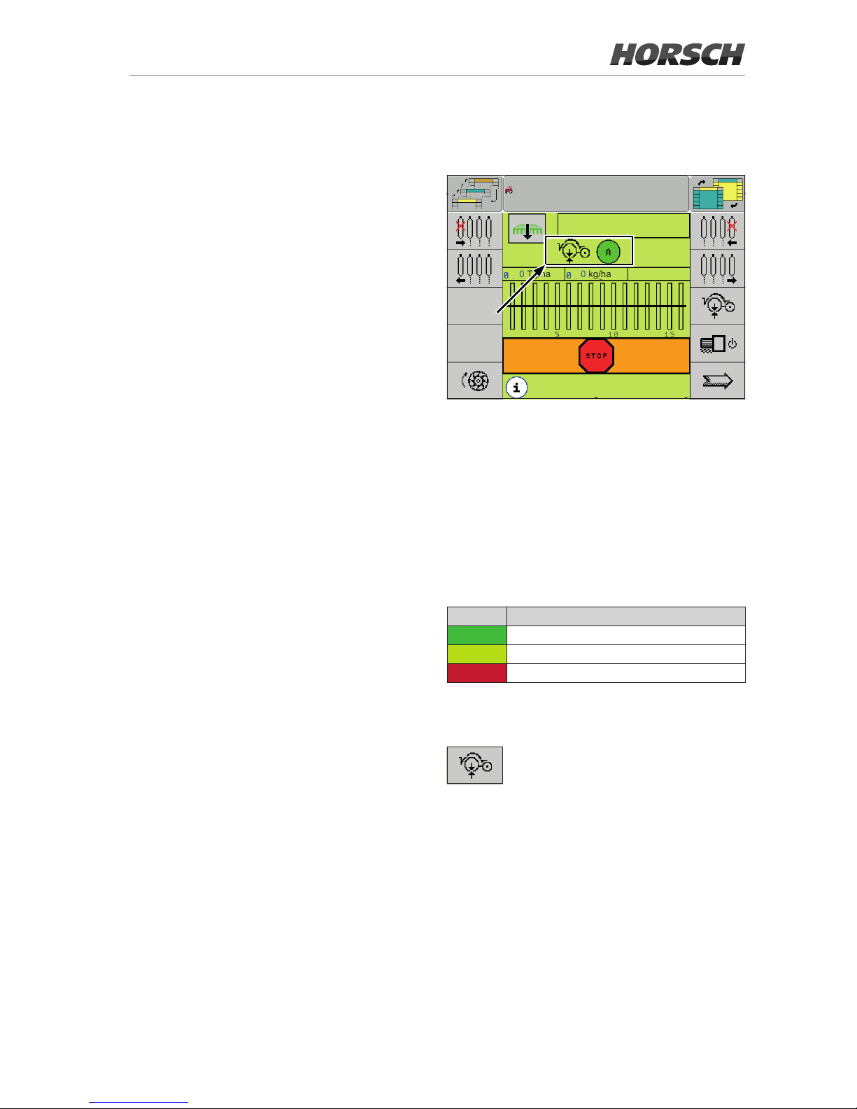
The work screen shows the coulter pressure
symbol together with the circle. The circle has
dierent colours according to the status (red/
yellow/green). The colour of the circle always
represents the value of the worst sensor.Depending on the terminal, the symbol can be
selected by rotary wheel or touch.
The following table explains the meaning of the
dierent colours of the dot:
Colour Meaning
green Coulter pressure okay.
yellow Coulter pressure too high.
red Coulter pressure too low.
Depending on the terminal, the symbol can be
selected by rotary wheel or touch.
Tool key to access the AutoForce
screen.
9
Page 12
Manual mode work screen
0.0
km/h
0 Tg/ha 0 kg/ha
maize
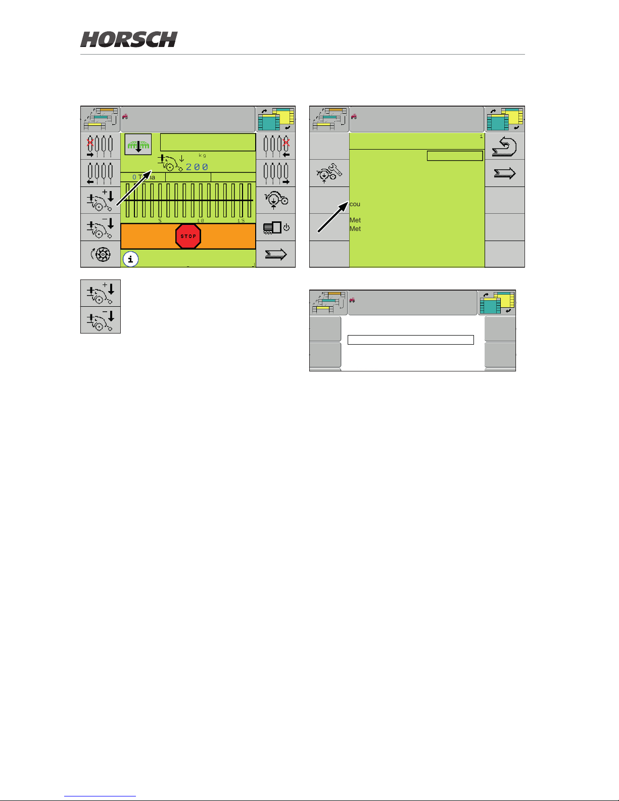
In manual mode the coulter pressure
is adjusted via these two softkeys. The
set pressure is shown in the centre of
the display.
Conguration
CONFIGURATION
Machine type : Maestro
Additional hopper : no
cent.hopper SOD : SOD 1x
Hydraulic valve block : no
coult.press.set : Hyd Auto
Metering unit 1: without
Metering unit 2: without
fertiliser monitoring : no
Detail view : no
Conguration 1
no
Hydac
Hyd Auto
Bucher
Bu Auto
Conguration options Coulter pressure adjustment
¾ Set the conguration option Coulter pressure
adjustment to Hyd auto (Hydac valve block)
or Bu auto (Bucher valve block) to activate
AutoForce.
¾ Always activate this setting if AutoForce is
installed, regardless whether the system is
used.
10
Page 13
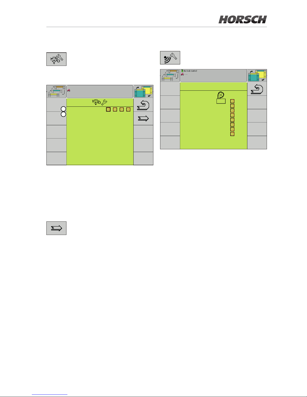
Settings
Softkey for accessing the AutoForce
settings.
Section selection
Current Sections :
Track section : sct4
1
2
1. Current (=active) sections
Depending on the equipment version, 1 - 4
sections can be enabled and disabled here.
2. Track section
The section for the track can be selected
here. By default, this is the highest section.
Softkey to the Section - row allocation page.
Sensor row allocation
Softkey for accessing the page for
sensor allocation.
CONFIGURATION
Sensor 1 : 2
Sensor 2 : 6
Sensor 3 : 9
Sensor 4 : 10
Sensor 5 : 14
Sensor 6 : 16
Sensor 7 : 19
Sensor 8 : 23
Sensor - row allocation
¾ Select the number of the row with the corre-
sponding sensor or enter it in the left column,
depending on the equipment of the machine.
¾ Mark the checkbox in the right column to se-
lect whether a sensor is installed or activated.
11
Page 14
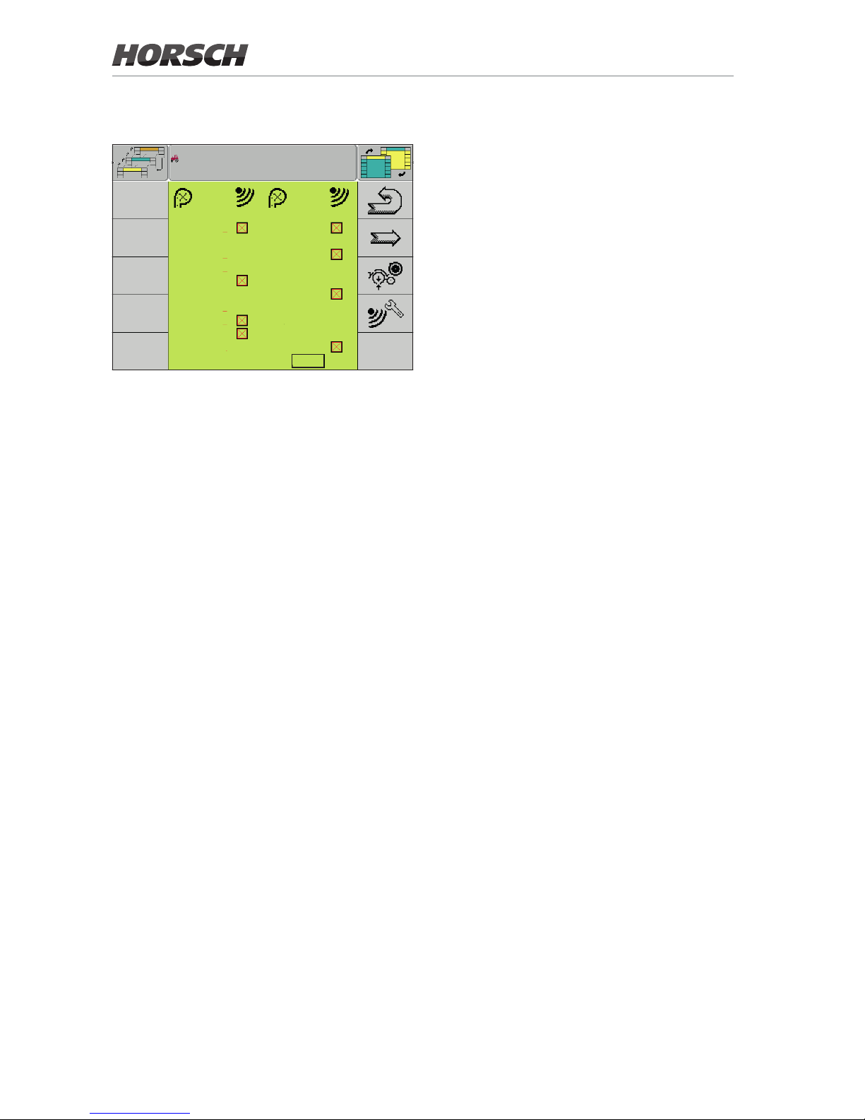
Section to row allocation
AF-S AF-S
1 : sct1 13 : sct2
2 : sct1 14 : sct4
3 : sct1 15 : sct4
4 : sct1 16 : sct2
5 : sct1 17 : sct2
6 : sct1 18 : sct3
7 : sct1 19 : sct3
8 : sct2 20 : sct3
9 : sct2 21 : sct3
10 : sct4 22 : sct3
11 : sct4 23 : sct3
12 : sct2 24 : sct3
Section - row allocation
¾ After allocating sensors to the row, allocate
the individual rows to the sections.
Between one and four sections can be allo-
cated, depending on the equipment version.
If so equipped, the status of the sensor is
indicated behind the respective row with allocated section.
¾ Activate or deactivate the sensors as needed.
12
Page 15
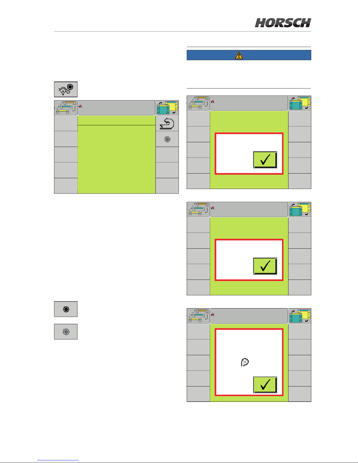
Calibrating (Teach) the sensors
¾ Calibrate the sensor after installation, replace-
ment or a software update.
Softkey for accessing the Calibration
page.
CALIBRATION
row 2 : row 14 :
3.55 mA 3.61 mA
4.63 mA 3.60 mA
row 6 : row 16 :
3.76 mA 3.96 mA
3.74 mA 3.57 mA
row 9 : row 19 :
4.01 mA 4.09 mA
4.00 mA 4.27 mA
row 10 : row 23:
4.10 mA 3.51 mA
3.52 mA 3.52 mA
Calibration
All allocated and active sensors are displayed
on the Calibration page.
The following prerequisites must be met to be
able to perform the calibration:
• No speed signal
• No working signal
• Machine unfolded
• Drill units do not touch the ground
• Value range (without load) in which the sensor
can be calibrated: 2.8 mA - 5.2 mA
The Teach softkey is displayed if all
prerequisites are met.
The Teach softkey is greyed if one of
the prerequisites is not met.
¾ Press the Teach softkey to calibrate.
All sensors are calibrated together.
¾ Check after calibration is completed whether
the current values of the sensors have been
accepted. They are displayed in light grey.
NOTE
Pop-up messages are displayed when the softkey Teach is pressed while grey. They indicate
which prerequisites have not yet been met.
Speed > 0
Calibration pop-up 1 - Machine not stopped
Working position
Calibration pop-up 2 - Machine still in working position
Calibration
not possible:
Sensor in row
outside
Value range:
Calibration range
2.80 - 5.20 mA
2
Calibration pop-up 3 - Sensor outside the value range
13
Page 16
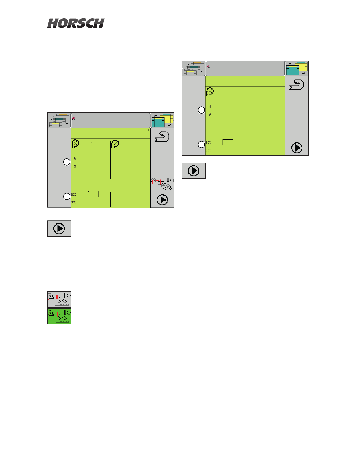
Diagnostics
Maestro 16/18 SW (row spacing >
60 cm)
Maestro 24/36/47/48 SW with
E-Manager software 10.07
DIAGNOSTICS
mA mA
2 : 3.88 sct 1 14 : 3.98 sct 4
6 : 3.78 sct 1 16 : 3.79 sct 2
9 : 0.02 sct 2 19 : 4.09 sct 3
10: 4.47 sct 4 23 : 3.68 sct 3
PWM :
sct 1 : 0 % sct 3 : 0 %
sct 2 : 0 % sct 4 : 0 %
1
2
Diagnostics
Softkey for transferring the current
value to the valve.
With the Maestro SW with E-Manager
version 10.07 listed above, the softkey
for preloading the units (active) must
be green and the valve needs to be
selected so that the PWM values can
be transferred.
Softkey for preloading the drill units.
The softkey is shaded green if the
units are preloaded.
1. All congured sensors are displayed in the
upper area of the Diagnostics screen. The
screen displays all current values of the
sensors.
2. In the lower area, a separate PWM value
(Pulse Width Modulation) can be set for each
hydraulic valve of each section.
¾ To do so, select the section, enter the value
and press the softkey to preload the units to
transfer the current value set to the valve.
Maestro CC / RC - 12/18 SW
DIAGNOSTICS
mA
2 : 3.98 sct 1
6 : 3.76 sct 1
9 : 4.11 sct 2
10: 3.52 sct 4
PWM :
sct 1 : 0 %
sct 2 : 0 %
1
2
Softkey for transferring the current
value to the valve.
1. All congured sensors are displayed in the
upper area of the Diagnostics screen. The
screen displays all current values of the
sensors.
2. In the lower area, a separate PWM value
(Pulse Width Modulation) can be set for each
hydraulic valve of each section.
¾ To do so, select the section, enter the value
and press the softkey to transfer the current
value set to the valve.
14
Page 17
Delta Step coulter pressure
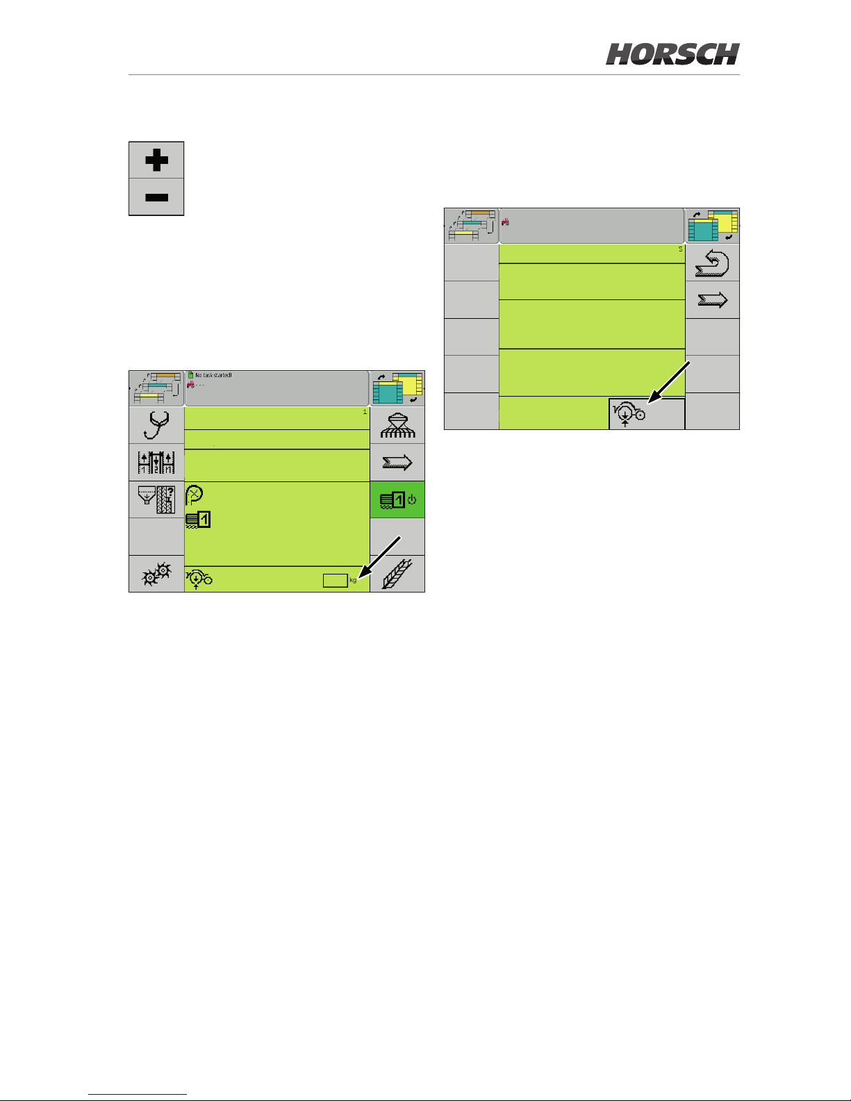
Softkey for changing the coulter pressure target value.
Incremental adjustment of the coulter pressure
can be individually adapted in the conguration
under the Delta Step point.
When adjusting the coulter pressure incrementally on the working screen or the AutoForce screen,
the values of the standard section and the values
of the section in the track are always changed
at the same time.
MACHINE DATA
crop : maize
Delta Step : 10
%
oset seed : 0.0
s
Delta Step : ON
Delta Step : ON
Delta Step : 5
kg
Machine data 1
Additional key
The AutoForce button can be assigned to the
additional key to speed up switching from the
working screen to the AutoForce screen.
CONFIGURATION
Tr. sect.reduct. . : no
Additional key :
Conguration 5 - additional key AutoForce
¾ Follow the operating instructions for the Maes-
tro E-Manager, Tool key selection to this end.
15
Page 18
Water hole mode
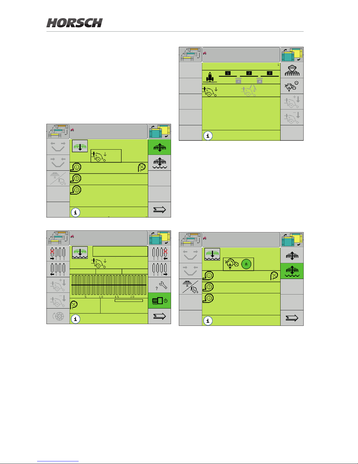
The drill units are lifted out in water hole mode.
No coulter pressure should therefore be applied.
The PWM value is to 0 while the water hole
mode is active.
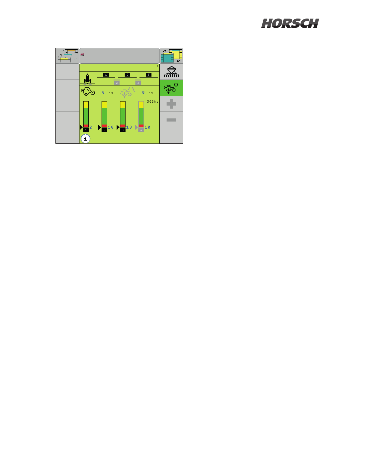
In manual mode, the display in the start screen
and the AutoForce detail screen is set to 0 kg
and shown as blue output value. All softkeys for
changing the target value are shown in grey.
5. 0
sim
km/h
kg
200
0
rpm
0
rpm
0
rpm
No
calculation of residual quantity
Normal mode, manual
5. 0
sim
km/h
kg
0
0.0 Tg/ha
VC
Ø Tg/ha
min. 0.0 Tg/ha
0.0
max. 0.0 Tg/ha
No
calculation of residual quantity
Water hole mode, manual work screen
AutoForce
0
kg
0
kg
Manual
maize
Water hole mode, AutoForce detail screen
In automatic mode, the status display of the
work screen switches to green when activating
the water hole mode, regardless of the value
on the sensors.
In the AutoForce detail screen, the display of
the target value for the coulter pressure is set
to 0 for all sections and shown as blue output
value. The softkeys for changing the target value
for the coulter pressure are shown in grey as in
manual mode.
0.0
km/h
0
1 / min
0
1 / min
0
1 / min
No
calculation of residual quantity
Water hole mode, automatic
16
Page 19
AutoForce
No
calculation of residual quantity
Water hole mode, AutoForce detail screen
17
Page 20
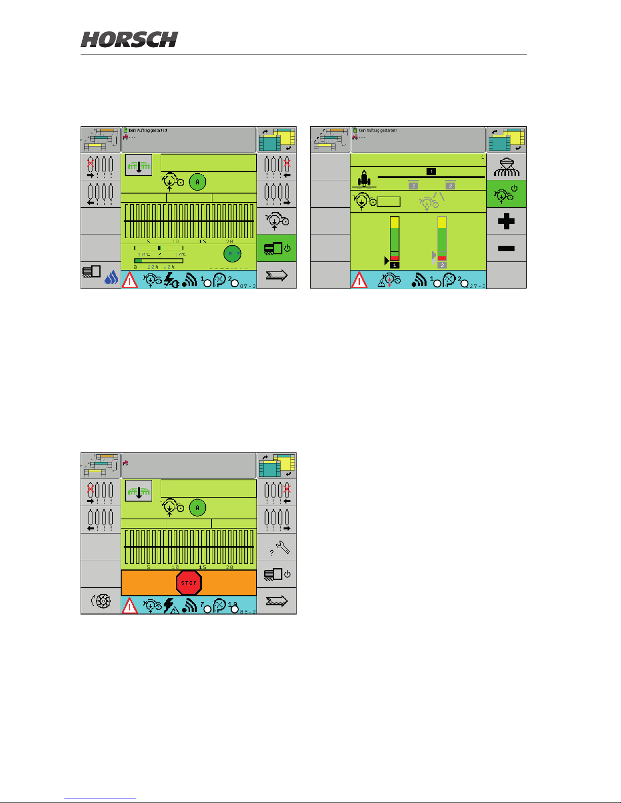
Ground contact lost (ErrorCode 127)
AutoForce
80
kg
80
kg
500 kg
2 9
A B
Working screen - ErrorCode 127
A Number of faulty sensor
B Row number of faulty sensor
No adequate coulter pressure can be built up.
The resistance is too great.
The warning message appears if the measured
force is too low over a certain period. There is
no ground contact. The correct placement depth
of the seed is no longer ensured.
¾ Increase the target value.
¾ Till the soil before sowing.
¾ Check the parallelogram on the drill unit for
free movement.
Error codes
Wire break (ErrorCode 87)
5.0
sim
km/h
180Tg / ha 0kg / ha
Tg 182
VC 9 %
Nom. : 100
%
A B
Working screen - ErrorCode 87
A Number of faulty sensor
B Row number of faulty sensor
The connection between job computer and sensor is interrupted.
¾ Check all cables and plug-and-socket con-
nections between job computer and sensor.
¾ Replace defective components as required.
Short-circuit (ErrorCode 88)
0.0
km/h
90 Tg/ha 0.0 kg/ha
A B
Working screen - ErrorCode 88
A Number of faulty sensor
B Row number of faulty sensor
There is a short-circuit between the sensor and
the job computer.
¾ Check all cables and plug-and-socket con-
nections between job computer and sensor.
¾ Replace defective components as required.
18
Page 21
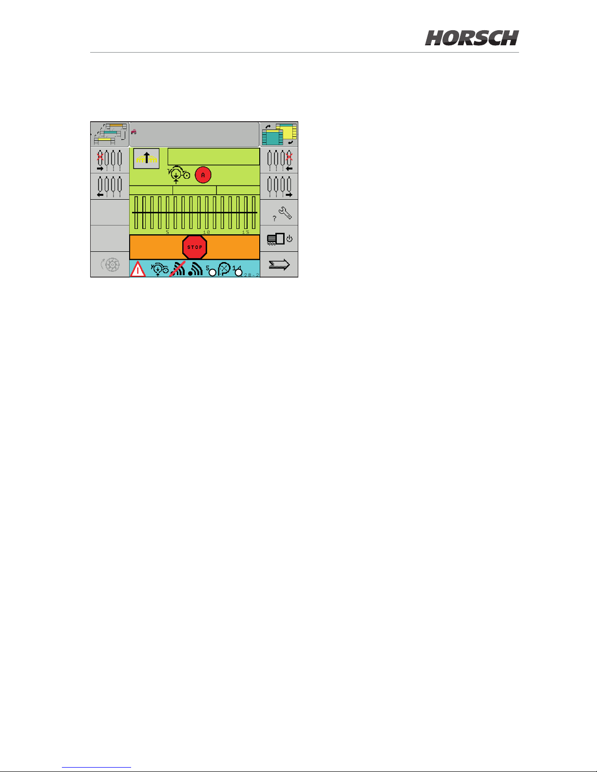
Sensor plastically deformed (ErrorCode 128)
A B
0.0
km/h
90 Tg/ha 0.0 kg/ha
Working screen - ErrorCode 128
A Number of faulty sensor
B Row number of faulty sensor
The sensor was plastically deformed. The original calibrated sensor value in unloaded condition
is not achieved again when lifting out.
¾ Check the sensor and replace it, if necessary.
Check the condition of the sensor while the
machine is lifted out. The sensor must rst
reach the taught mA value when without load.
If the system detects plastic deformation, the
sensor is no longer included in the calculation
of the control values. The sensor is included
again for the control after the problem has been
corrected and the system restarted.
¾ Re-teach sensor after replacement.
19
Page 22
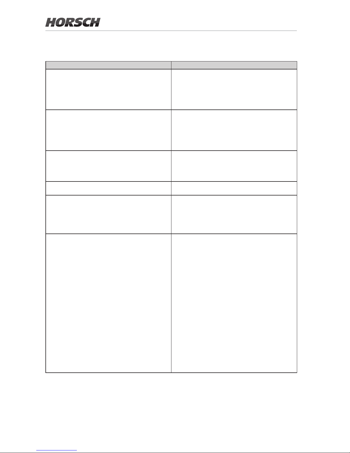
Troubleshooting
Display / error Meaning
Bar graph
Coulter pressure always in the yellow range
Contact force of the depth guide wheels on the ground
too high.
Check the detail screen / Machine data 3 screen
Bar graph
Coulter pressure always in the red range
The contact force of the depth guide wheels on the
ground is too high.
The drilling depth is not kept.
Check the detail screen / Machine data 3 screen
Ground contact lost message
No adequate coulter pressure can be built up. The
resistance is too great.
The force measured is too low over a certain period.
There is no ground contact. Correct seed placement is
not ensured.
Plastic deformation message
The sensor is no longer included in the calculation of the
values of the control.
No coulter pressure in manual or automatic mode
Sensor calibration (Teach) not possible The following prerequisites must be met to be able to
perform the calibration:
• No speed signal
• No working signal
• Machine unfolded
• Drill units do not touch the ground
• Value range (without load) in which the sensor can be
calibrated: 2.8 mA - 5.2 mA
One or more of these prerequisites are not met.
20
Page 23
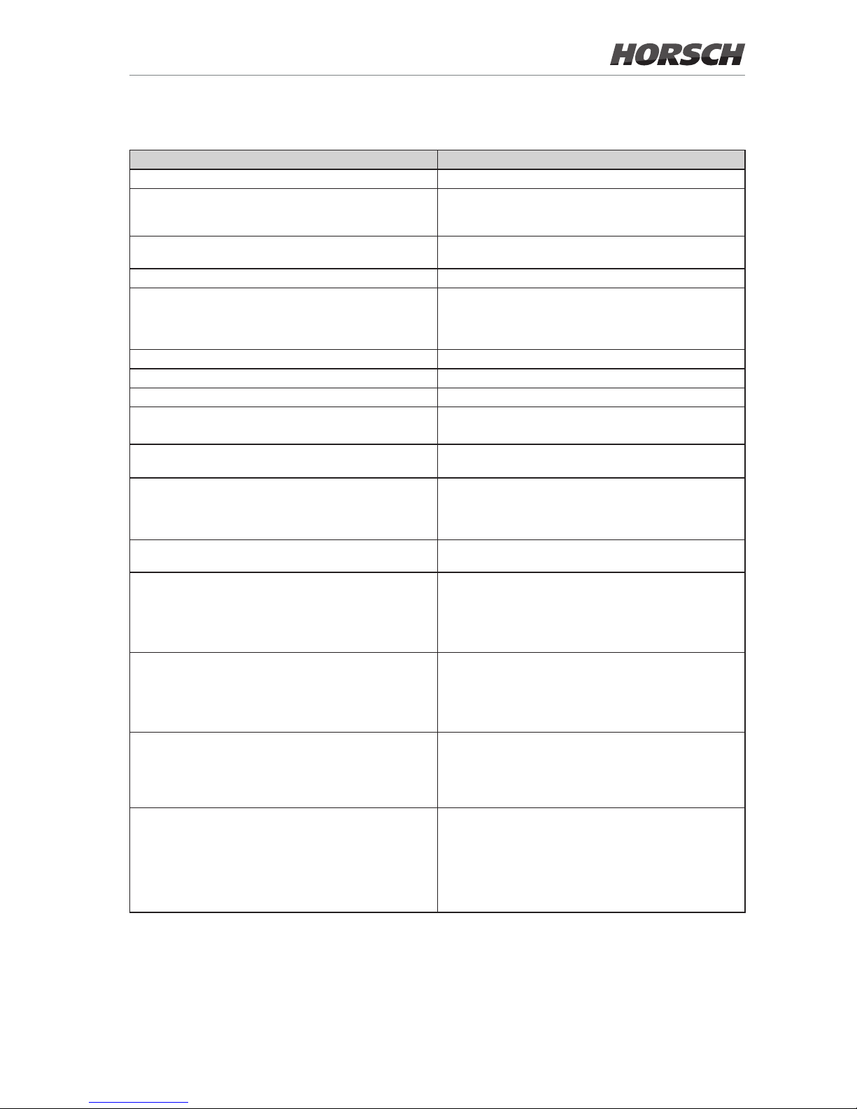
Possible causes Solution options
The target value is set too low. Check nominal value setting.
The dead weight of the drill unit is too high (the hydraulic
coulter pressure display on the hopper shows 0 bar at
light soil conditions).
Sensor zero point shift / sensor is defective. Recalibrate the sensor or replace the sensor if calibration
is not possible.
The drilling speed is too high. Reduce the drilling speed.
The hydraulic coulter pressure is too low.
Feed pressure fan = coulter pressure
¾ Check the pressure gauge on the fertiliser hopper.
Increase the speed of fertiliser and Seed On Demand
fan (pneumatic bypass, consultation with HORSCH
required).
Springs required for pretension of the drill units.
Working conditions too tough. Tillage necessary
The target value is too low. Increase the target value.
Working conditions too tough. Tillage necessary.
Free movement of the parallelogram on the drill unit is
limited.
Check the parallelogram and restore free movement.
The sensor was plastically deformed. Check the sensor and replace it, if necessary.
Note the section Sensor plastically deformed (ErrorCode 128).
Faulty conguration Check the conguration settings:
Under Coulter pressure adj. Hyd auto or Bu auto must be
selected.
Follow the Conguration section in this regard.
Coulter pressure valves defective Check the selection of the coulter pressure valves in the
Diagnostics menu.
Wire break (ErrorCode 87) The connection between job computer and sensor is
interrupted.
¾ Check all cables and plug-and-socket connections
between job computer and sensor.
¾ Replace defective components as required.
Short-circuit (ErrorCode 88) There is a short-circuit between the sensor and the job
computer.
¾ Check all cables and plug-and-socket connections
between job computer and sensor.
¾ Replace defective components as required.
Sensor zero point shift
Open Diagnostics and check the sensor values.
Values without load: 3.8 - 4.5 mA
Values with excessive load: > 4.5 mA
Sensor can be calibrated if the value lies between
2.8 - 5.2 mA.
Sensor must be checked Without load (drill unit raised, machine unfolded) the
value of the sensor is roughly 4 mA.
The value changes by lifting the corresponding depth
guide wheel.
Never place objects under the depth guide wheels and
lower the coulter bar on it. The entire machine weight
rests on the sensor. It is destroyed from overload.
21
Page 24
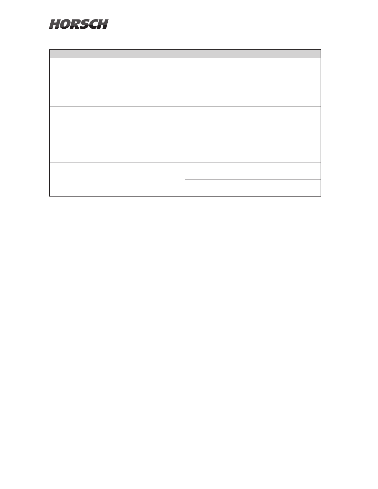
Display / error Meaning
Sensor failure The system continues working as long as one sensor
still functions.
Check if the use of AutoForce is still practical.
Check the coulter pressure Check the selection of the coulter pressure valve.
Uneven placement depth Placement depth diers from row to row.
Placement depth in row varies.
22
Page 25
Possible causes Solution options
Short-circuit (measured value > 25 mA); the input to the
job computer was disabled.
Turn the machine o and on again. The job computer is
reset if the fault was rectied.
Wiring between sensor and slave computer is defective. Replace the aected component.
Sensor defective. Replace the sensor.
Deactivate the failed sensors in the parameter screen.
Switch to manual mode.
Open Diagnostics and check the sensor values.
Switching on the fertiliser and demand fan.
Adjust the % values in diagnostics.
The hydraulic pressure rises when increasing the PWM
signal; observe the pressure gauge on the fertiliser
hopper.
Only values in the range of 25-55 % cause a change of
the hydraulic pressure.
Cam wear diers from row to row. Replace cams.
Sensor calibration values not okay. Teach sensor.
Speed too high. Reduce the speed.
Sensor calibration values not okay. Teach sensor.
23
Page 26

Index
A
Additional key 15
Allocation 12
AutoForce screen 7
Automatic mode 8
B
Basic setting 4
C
Calibration 13
Checks 4
Conguration 9
D
Delta Step 15
Diagnostics 14
E
Error codes 18
F
Functional principle 5
M
Manual mode 7
T
Teach 13
Troubleshooting 21
W
Work screen 7
24
Page 27

Page 28

www.horsch.com
All details on technical specifications and pictograms are approximate
and for information only. Subject to technical product revisions.
HORSCH Maschinen GmbH
Sitzenhof 1
92421 Schwandorf
Tel.: +49 94 31 7143-0
Fax: +49 94 31 7143-9200
E-Mail: [email protected]
 Loading...