

Page 1
1
Page 2

2
1. Description
2. Operation
3. Connections
3.1 Battery
3.2 AC adapter
3.3 Precision probes
4. Settings
4.1 Mute
4.2 Reset
4.3 Calibration
5. Screen information
6. Measurements and functions
7. Settings
8. Switching on the device
8.A Measuring tension of unloaded batteries
8.B Measuring tension of under load batteries
8.C Measuring the movement supply voltage
8.D Measuring the coil resistance
8.E Unjamming the wheel trains
8.F Measuring (gain/loss) the stability of the rate of a watch or movement
8.G Checking the correct functioning of the circuit
8.H Measuring the consumption of a watch during its operation
8.I Settings
9. Safety precautions
10. Charter of consumption of electronic circuits / coils resistance
3
3
4
4
4
4
4
4
4
4
5
6
7
7
7
8
9
10
11
11
12
14
15
16
18
TABLE OF CONTENTS
Page 3
3
1. DESCRIPTION
2. OPERATION
HOROTEC© Flashtest is a multifunctional portable touchscreen tester, specifically designed for the control of watches and quartz mechanisms.
This precision device is easy to handle and is intended to test analogue quartz watches and movements with both closed and open watchcases.
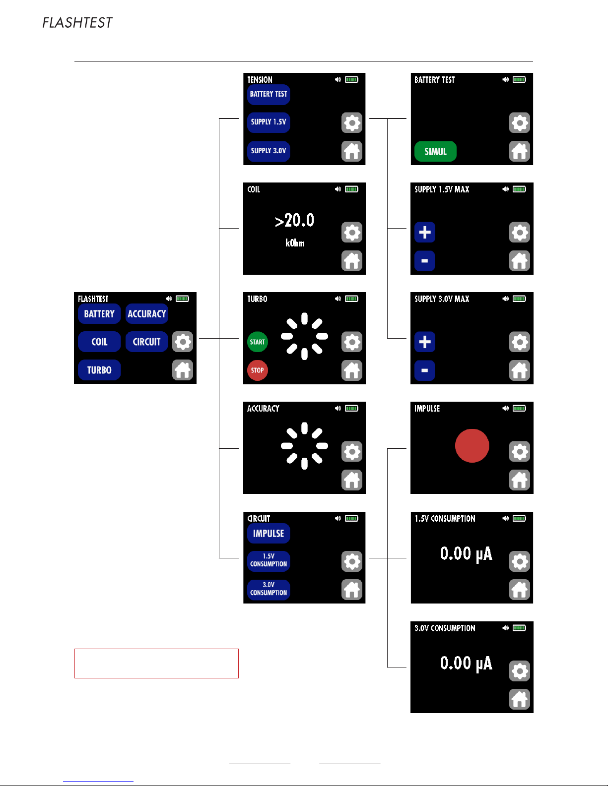
HOROTEC© Flashtest is able to:
A. Measuring tension of unloaded batteries from 0 to 19.999 V.
BATTERY
+
BATTERY TEST
B. Measuring tension of batteries under load from 0 to 19.999 V.
BATTERY
+
BATTERY TEST
+
SIMUL
C. Measuring the movement supply voltage (1.5 V or 3.0 V).
BATTERY
+
SUPPLY 1.5V
ou
SUPPLY 3.0V
D. Measuring the coil resistance.
COIL
E. Unjamming the wheel trains.
TURBO
F. Measuring (gain/loss) the stability of the rate of analogue quartz watches.
ACCURACY
G. Checking the correct functioning of the circuit :
CIRCUIT
a. Electrical impulse
CIRCUIT
+
IMPULSE
b. Measuring the consumption of the electric circuit.
CIRCUIT
+
1.5V CONSUMPTION
or
3.0V CONSUMPTION
H. Measuring the consumption of a watch during its operation.
CIRCUIT
+
1.5V CONSUMPTION
or
3.0V CONSUMPTION
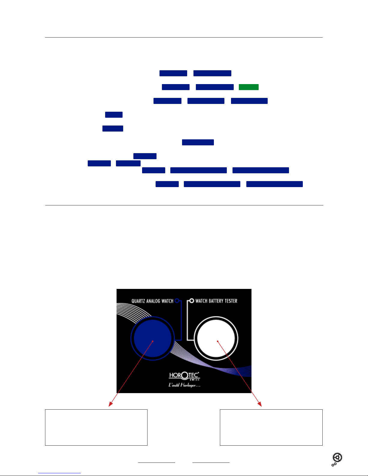
WATCH BATTERY TESTER : The following tests are made on the metal plate on the right of the device :
A. Measuring tension of unloaded batteries.
B. Measuring tension of batteries under load.
QUARTZ ANALOG WATCH : The following tests are made on the blue velvet plate on the left of the device :
E. Unjamming the wheel trains.
F. Measuring (gain/loss) the stability of the rate.
G. Checking the correct functioning of the circuit : electrical impulse and measuring the consumption of the electric circuit.
E. Unjamming the wheel trains.
F. Measuring (gain/loss) the stability of the rate.
G. Checking the correct functioning of the circuit.
A. Measuring tension of unloaded batteries.
B. Measuring tension of batteries under load.
Page 4
4
4. SETTINGS
3. CONNECTIONS
1. Mute : silent mode or sound mode.
MUTE
see paragraph 8.I2 on page 15
2. Calibrage : calibration of the built-in quartz oscillator. During the conception of our HOROTEC© Flashtest, we focused on the measurement accuracy. To ensure
this accuracy we fitted in the device a calibration function ensuring the continuous checking of the device and the correction of errors due to the quartz aging.
The calibration is a very simple process.
CALIBRATION
see paragraph 8.I2 on page 15
3. Reset (values reset) : resets the real value of the corrupted zero by measurements of voltage and electricity. It’s a simple and easy process.
RESET
see paragraph 8.I2 on page 15
Recommendations :
It is not always possible to realise some tests or measurements with the watchcase closed, especially with a steel and/or thick watchcase. In this case, the case
back has to be open.
When operating on battery, we recommend to limit the duration of some tests, such as battery tests or the turbo function, in order to avoid a too fast discharge
of the battery.
Do not touch the watch batteries with your hands to avoid a redox reaction on the surface of the battery.
1. Battery : unscrew the battery cover on the back of the HOROTEC© Flashtest and insert the 9 V battery delivered with the device
Note: change the battery if the symbol «discharged battery» appears on the screen of the HOROTEC© Flashtest when the device is on.
2. AC adapter : connect the 12 V adapter to rear jack of the device HOROTEC© Flashtest. Connect the cord of the AC adapter to the power sector (115 or
230 V). Once the device is connected to the power sector, the 9 V battery is automatically disconnected to allow its economy.
3. Precision probes : connect the two precision probes to the jacks on the rear plate of the HOROTEC© Flashtest (plug the black probe in the black jack
and the red probe in the red jack).
HOROTEC© Flashtest is delivered with two precision probes, a 12 V adapter (input 115 - 230 V AC / output 12 V DC), a 9 V battery and a manual. HOROTEC© is
a registered trademark in Switzerland, United States, European Union and many other countries.
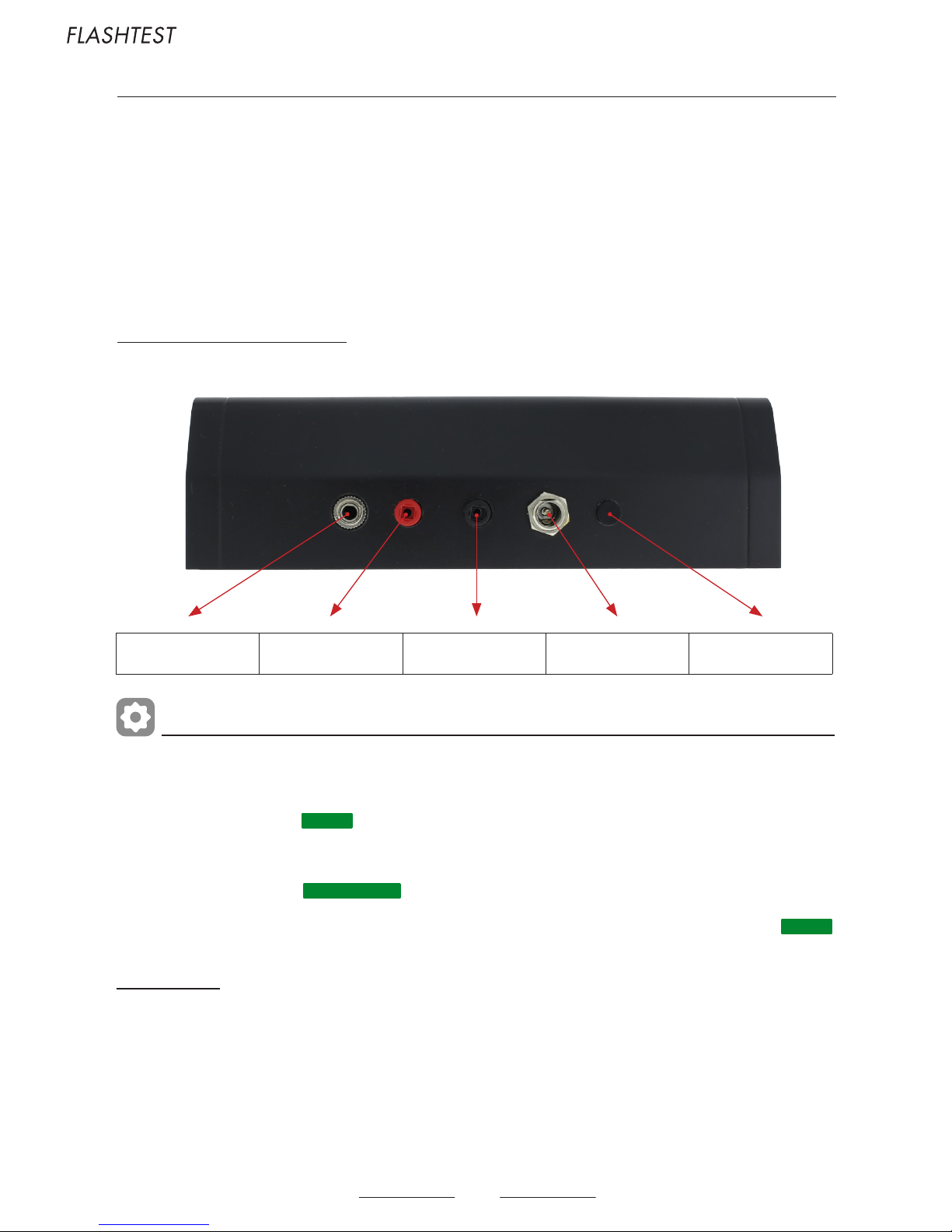
Connections to the rear panel of the device :
Connection for the calibration Positive probe Negative probe
Power supply
sector 110 - 220 V
Button ON/OFF
Page 5
5
5. SCREEN INFORMATION
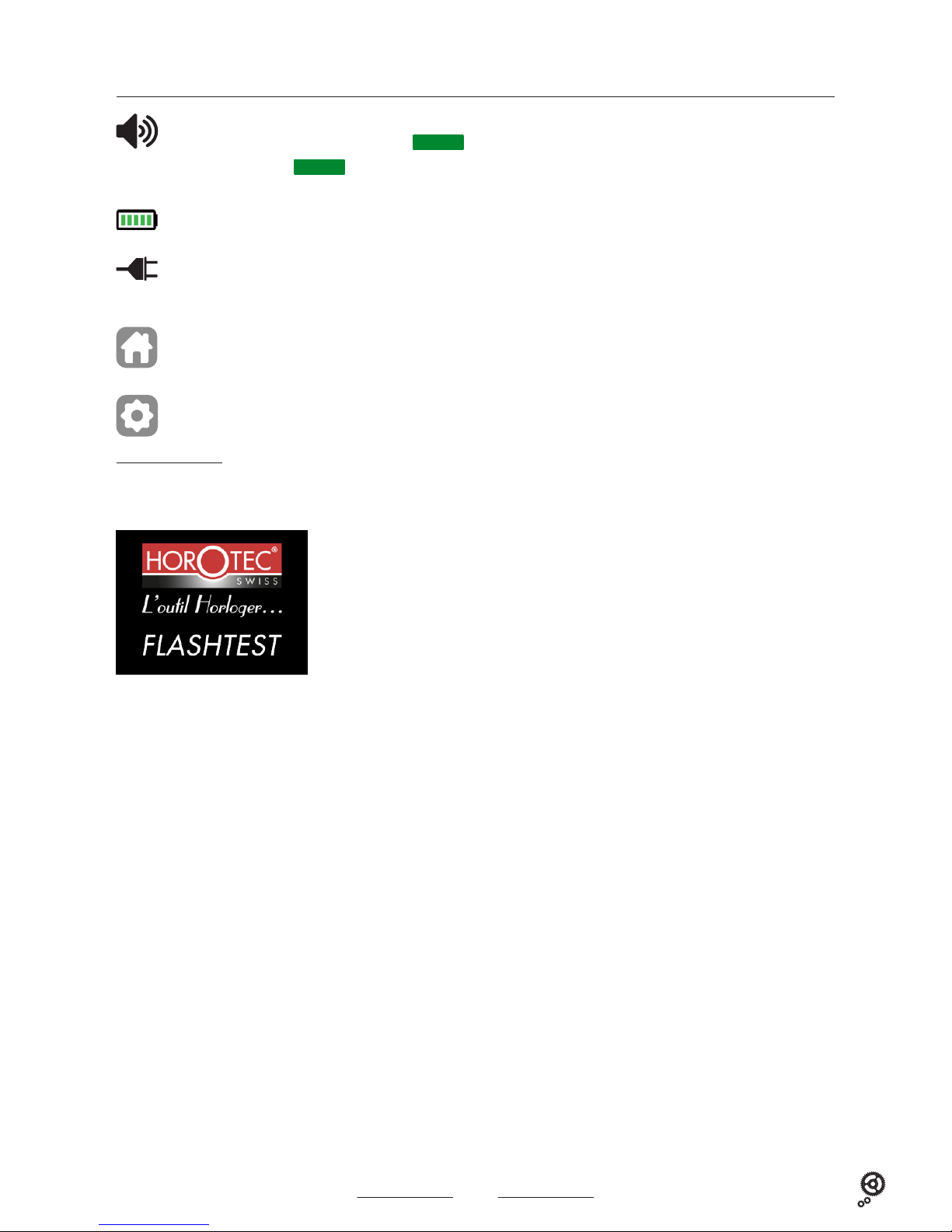
Sleep mode screen :
1. When the device is connected to the power sector (115 - 230 V), the screen goes to sleep mode after 2 minutes without use. To reactivate its operation, press
the ON/OFF button located at the rear panel of the device.
When this symbol is visible, the device emits sound signals.
When this symbol does not appear on the screen, the
MUTE
function is activated and the device is silent.
To activate/deactivate the
MUTE
function. see paragraph 8.I2 on page 15
When this symbol is visible, the device runs on the battery. The number of green bars indicates the battery charge level.
When this symbol is visible, the device is connected to the power sector 115 - 230 V.
The battery is automatically disconnected to allow its economy.
Return to the main menu.
Press this icon at any time to return to the main menu.
Settings. see paragraph 8.I on page 15
2. When the device is running on the battery, the screen goes to sleep mode after 2 minutes without use. To reactivate its operation, press the ON/OFF button
located at the rear panel of the device.
Touch the screen to return to the main menu.
Display in sleep mode.
Page 6
6
6. MEASUREMENTS AND FUNCTIONS
Special signals displayed on the screen :
<-> Waiting for measure
Page 7

7
7. SETTINGS
8. SWITCHING ON THE DEVICE
see paragraph 8.I on page 15
Whatever the used mode is, power sector (115 - 230 V) or battery, press the ON/OFF button located at the rear panel of the device to turn it on.
The following screen displays :
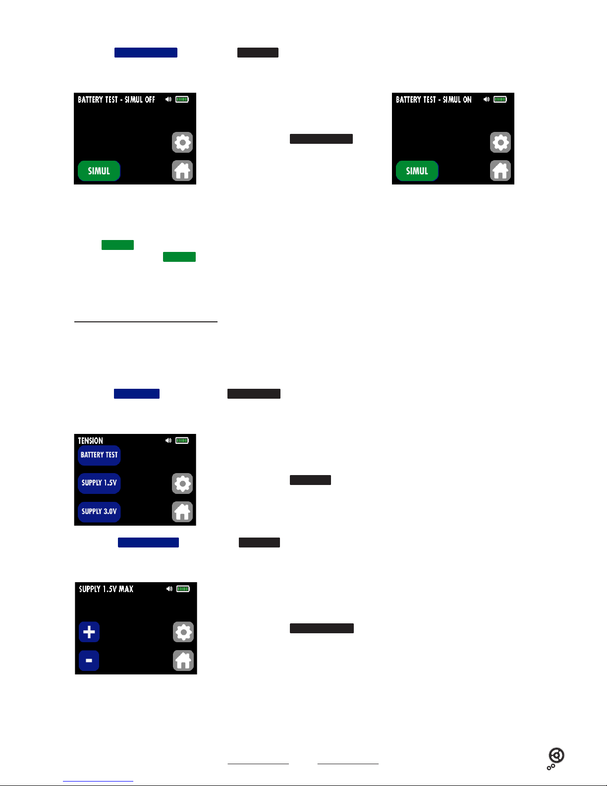
A. Measuring tension (V) of unloaded batteries
A1. Press the
BATTERY
key on the main menu
FLASHTEST
to measure the unloaded battery voltage (V) (non-operating).
The following screen displays :
Display of the main menu
FLASHTEST
Key
BATTERY
A. Measuring tension of unloaded batteries
B. Measuring tension of batteries under load
C. Measuring the movement supply voltage
Key
COIL
D. Measuring the coil resistance
Key
TURBO
E. Unjamming the wheel trains
Key
ACCURACY
F. Measuring (gain/loss) the stability of the rate
Key
CIRCUIT
G. Checking the correct functioning of the circuit
H. Measuring the consumption of a watch during its operation
Display of the submenu
TENSION
Display when using the GPS MSA19.108-E
Page 8

8
A2. Press the
BATTERY TEST
key of the submenu
TENSION
The following screen displays :
B. Measuring tension (V) of batteries under load
B1. Press the
BATTERY
key on the main menu
FLASHTEST
to measure the battery voltage under load (V) (operating).
The following screen displays :
There are 2 possibilities to measure the voltage of an unloaded battery :
- Battery only : place the battery on the metal plate of the device.
Place the positive pole (+) of the battery on the metal plate, so the negative pole (-) will be positioned upwards. Use the black precision probe (-)
and place it on the negative pole (-) of the battery. Read the battery voltage on the screen of the device.
- Movement with battery : place the movement with the battery on the metal plate.
See the sketch below.
Display of the sub-submenu
BATTERY TEST
Display of the sub-submenu
TENSION
Illustration refers to movement ETA 955112.
Note : in this case, only the unloaded battery voltage can be measured !
Caution : we recommend to limit the duration of the battery test to avoid that the battery discharges too quickly.
Do not touch the watch batteries with your hands to avoid a redox reaction on the surface of the battery
- 0.00 V
<->
Page 9
9
C2a. Press the
SUPPLY 1.5V
key of the submenu
TENSION
if the watch is supplied with 1.5 V.
The following screen displays :
C. Measuring the movement supply voltage
Connaître le point d’arrêt d’un mouvement est une information très importante permettant de définir l’origine de la panne.
Si la tension d’arrêt indiquée à l’écran est supérieure à celle donnée par le fabricant (exemple : mouvement ISASWISS 1198, tension d’arrêt 0.8 V), cela signifie
que le mouvement est encrassé ou endommagé. Ceci explique le besoin d’énergie supplémentaire.
Dépannage : nettoyer ou changer le rouage.
C1. Press the
BATTERY
key on the main menu
FLASHTEST
to measure the movement supply voltage.
The following screen displays :
This measurement is performed only with the single battery : place the battery on the metal plate of the device.
Place the positive pole (+) of the battery on the metal plate, so the negative pole (-) will be positioned upwards. Use the black precision probe (-) and place
it on the negative pole (-) of the battery.
Press the
SIMUL
key to simulate the power consumption of the watch with a 1000 Ohm resistance. Read the battery voltage (under load) on the screen of
the device (2). Press again the
SIMUL
key to remove the load of 1000 Ohm (1).
Caution : we recommend to limit the duration of the battery test to avoid that the battery discharges too quickly.
Do not touch the watch batteries with your hands to avoid a redox reaction on the surface of the battery.
Display of the sub-submenu
SUPPLY 1.5V
Display of the sub-submenu
TENSION
B2. Press the
BATTERY TEST
key of the submenu
TENSION
The following screen displays :
Display of the sub-submenu
BATTERY TEST
- 0.00 V
<->
- 0.00 V
<->
1.50 V
(1) (2)
Page 10

10
C2b. Press the SUPPLY 3.0V key of the submenu TENSION if the watch is supplied with 3.0 V.
The following screen displays :
D. Measuring the coil resistance
The measuring range is 0 - 20 kΩ.
The voltage of the ohmmeter is 0.2 V during the operation (a higher voltage than this value could corrupt the measurement).
Caution : always remove the battery before measuring. The coil should not receive electrical energy during the measurement.
D1. Press the
COIL
key on the main menu
FLASHTEST
to measure the coil resistance.
The following screen displays :
Display of the sub-submenu
SUPPLY 3.0V
Display of the sub-submenu
COIL
- To reduce the tension, press the key (or the key to increase it), by steps of 0.1 V for a
supply of 1.5 V or 0.2 V for a supply of 3.0 V.
- Identify on the screen the voltage displayed during the movement supply voltage and compare it with the data
of the manufacturer.
The measured resistance values indicate the following problems :
- Broken coil : resistance = > 20.0 kOhm
- Shortcut coil : resistance = 0
- Not suitable coil : when the measured value is different from the one indicated by the manufacturer.
The «not suitable» status generates additional consumption and shorten the battery life. Compare the measured
value to the one specified by the manufacturer.
Use the probes to supply the movement as shown on the sketch below.
Use the probes and place them as shown on the sketch below.
3.00 V
Page 11

11
E. Unjamming the wheel trains
It is possible that a watch does not restart immediately after a battery change or a prolonged stoppage.
It is then necessary to generate a powerful magnetic field to test or unjam the wheel train.
If during this action the hands do not make a fast rotation, it means that a wheel (or wheels) is broken or that the wheel train is too dirty.
E1. Press the
TURBO
key on the main menu
FLASHTEST
to unjam the wheel trains.
The following screen displays :
F. Measuring the stability of the rate (gain/loss) of a watch or movement
The tester for analogue quartz watches receives magnetic signals from the motor of the watch. The device measures the stability of the rate of the watch and
calculates an average by a specific method from the received impulses (the average is given in sec/month).
F1. Press the
ACCURACY
key on the main menu
FLASHTEST
to measure the stability of the rate.
The following screen displays :
Place the watch on the blue velvet plate.
Press the key and check if the hands have a fast rotation. Press to the test.
Note 1 : when operating on battery, reduce the test duration to preserve the capacity of the device battery.
Note 2 : it is sometimes necessary to move or turn the watch on the sensor plate to find the ideal position.
Place the watch on the blue velvet plate.
The generation time of signals (1, 2, 5, 10, 20, 30 or 60) will appear on the screen after a few seconds (sec/pulse). (1)
In the middle of the screen the number of required impulses at the beginning of the analysis (60/generation time of signals) will be displayed. The software starts
a countdown by pulsations. Once the countdown is finished, the rate accuracy of the watch will be displayed on the screen (in sec/month, for example : -1.75 sec/
month). (2)
There are 5 signal levels. The more bars displayed (1 bar = low, 3 bars = medium, 5 bars = optimal), the more the measurement precision. (3)
If a watch is detected when the main menu
FLASHTEST
is displayed or the device is in sleep mode, the screen will automatically switch to the submenu
ACCURACY
.
Display of the sub-submenu
TURBO
Display of the sub-submenu
ACCURACY
(1)
(2)
(3)
Example : 66 = current cycle time
Page 12

12
G. Checking the correct functioning of the circuit
Electric pulse
Ga1. Press the
CIRCUIT
key on the main menu
FLASHTEST
to check the electric impulses.
The following screen displays :
Ga2. Press the IMPULSE key of the submenu CIRCUIT.
The following screen displays :
Place the watch on the blue velvet plate of the HOROTEC© Flashtest to make the fast test mentioned below (without precision probe).
The sensor receives the impulses of quartz mechanisms and represents them on the screen with a red circle (see picture below) and sound signals (beep) :
- Every second for «seconds» watches
- Every 5, 10, 20, 30 or 60 seconds for other watches
- Note : it is sometimes necessary to move or turn the watch on the sensor plate to find the ideal position for the perception of signals
Place the open watch or the mechanism on the blue velvet plate. Account should be taken of the fact that certain mechanisms generate signals every second,
while others only generate every 5, 10, 20, 30 or 60 seconds.
- If the HOROTEC© Flashtest receives impulses, but the hands do not turn, there is a mechanical problem.
Troubleshooting : check and/or clean the mechanical parts of the watch (blocked hands, dust, etc.).
- If the watch does not work, although it receives impulses, check the status of the coil as indicated previously. see paragraph 8.D on page 10
Display of the sub-submenu
CIRCUIT
Display of the sub-submenu
IMPULSE
Page 13

13
G. Checking the correct functioning of the circuit (continued)
Measuring the consumption of the electric circuit
Gb1. Press the
CIRCUIT
key on the main menu
FLASHTEST
to measure the consumption of the electric circuit.
The following screen displays :
Gb2. Press the
1.5V CONSUMPTION
key of the submenu
CIRCUIT
if the watch is supplied with 1.5 V.
The following screen displays :
Gb3. Press the
3.0V CONSUMPTION
key of the submenu
CIRCUIT
if the watch is supplied with 3.0 V.
The following screen displays :
Display of the sub-submenu
CIRCUIT
Display of the sub-submenu
1.5V CONSUMPTION
Display of the sub-submenu
3.0V CONSUMPTION
Use the probes and place them as shown on the sketch below.
- Measuring range : 0 … 19.999 μA
- PULL THE WINDING STEM FULLY
- Remove the battery.
Caution : always choose the right polarity. NEVER CHOOSE the function 3.0 V for a 1.5 V watch.
Compare the measured value to the one specified by the manufacturer or in this manual.
- A zero consumption (0) indicates a breakdown of circuit.
Troubleshooting : change the circuit.
- If the consumption is higher or lower than the one stated by the manufacturer, the circuit is defective.
Troubleshooting : it is strongly recommended to change the circuit.
Page 14

14
H. Mesurer la consommation d’une montre pendant son fonctionnement
H1. Appuyer sur la touche
CIRCUIT
du menu principal
FLASHTEST
pour mesurer la consommation de la montre.
The following screen displays :
H2a. Appuyer sur la touche
1.5V CONSUMPTION
du sous-menu
CIRCUIT
si la montre est alimentée en 1.5 V.
The following screen displays :
H2b. Appuyer sur la touche
3.0V CONSUMPTION
du sous-menu
CIRCUIT
si la montre est alimentée en 3.0 V.
The following screen displays :
Display of the sub-submenu
CIRCUIT
Display of the sub-submenu
1.5V CONSUMPTION
Display of the sub-submenu
3.0V CONSUMPTION
Use the probes and place them as shown on the sketch below.
- Measuring range : 0 … 19.999 μA
- Remove the battery
- PRESS THE WINDING STEM TO ACTIVATE ALL FUNCTIONS.
Caution : always choose the right polarity. NEVER CHOOSE the function 3.0 V for a 1.5 V watch.
Note : wait 5-10 seconds to get reliable results.
Compare the measured value to the one indicated in the manual. If the consumption is different than the one
stated by the manufacturer :
- The wheel trains are dirty or damaged which increases the friction of parts and the energy requirements of the
wheel trains.
Troubleshooting : clean, set up or change the wheel trains.
- The hands touch the dial or the watch crystal or they are loose.
Troubleshooting : adjust, clean or change the hands.
Page 15

15
I. Settings
I1. Press the key on the main menu
FLASHTEST
to set up the device.
The following screen displays :
I2.
MUTE
mode
Press the
MUTE
key, the symbol disappears (silent mode) or appears (sound mode).
I3.
RESET
mode
Values reset : resets the real value of the corrupted zero by measurements of voltage and electricity.
Press the
RESET
key, the following screen displays :
Display of the sub-submenu
SETTINGS
Display of the sub-submenu
CALIBRATION
Display of the sub-submenu
RESET
Note : when restarting the device, the reset is done automatically.
I4.
CALIBRATION
mode
Using the GPS MSA19.108-E (item sold separately), it is possible to proceed regularly with the calibration of the device.
Press the
CALIBRATION
key, the following screen displays :
Connect the GPS MSA19.108-E to the rear panel of the device. see paragraph 3 on page 4
- The calibration value is displayed on the screen. As soon as the calibration value stabilizes (example -1.94), press the
SAVE
key. The calibration
is completed.
- Press the key to return to the main menu
FLASHTEST
.
The displayed value is the value to be corrected. Press the
SAVE
key to save the counter-value.
Page 16
16
9. SAFETY PRECAUTIONS
Copyright law protects the contents of this operating manual. Law prohibits reproduction, and using its elements without the written consent of the manufacturer
and the importer.
Before you use the HOROTEC© Flashtest product, read all operating instructions because it can provide optimum performances and longer service life for
your device. Save all manuals and documentation for future reference.
The manufacturer reserves the right to modify or update the information contained in this guide.
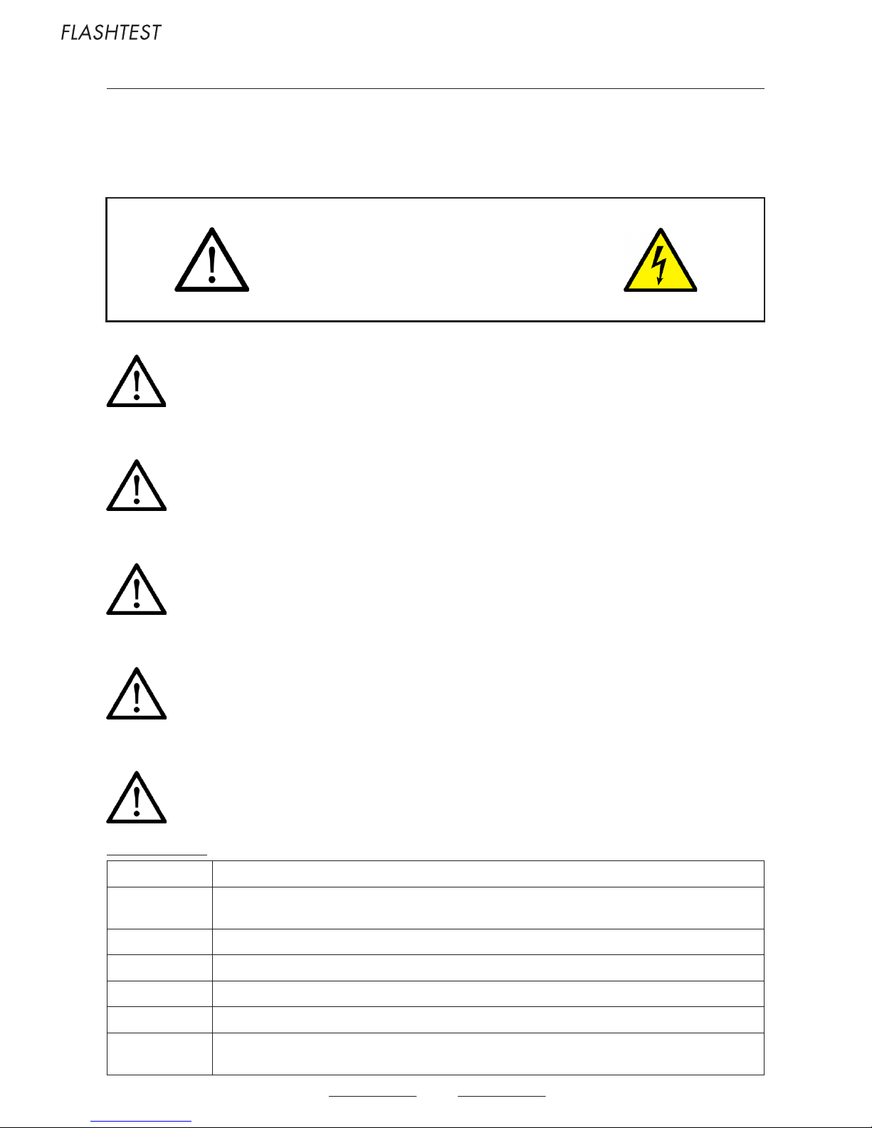
WARNING !
Danger of electrocution.
To avoid the risk of electric shock, do not remove the cover.
No user serviceable parts inside.
General precautions :
Read all instructions : Before you use the product, read all operating instructions
Cleaning :
Always unplug this product from the wall outlet before cleaning. Use only a damp cloth for cleaning. Never use any type of fluid or
aerosol cleaner, or any type of organic solvent to clean this product.
Accessories : For your safety, and to avoid damaging the product, use only accessories recommended by HOROTEC SA
Water/Moisture: Do not use the product near a water or moisture source.
Power supply : Connect this product only the power source described on the product label.
Lightning : If a lightning storm occurs while using an AC adapter, remove it from the wall outlet immediately
Heat :
Never use or store this product near any heat source such as a radiator, heat register, stove, or any type of equipment or appliance
that generates heat
An exclamation mark enclosed in a triangle alerts the user to important operating and maintenance instructions in the documentation provided
with the product.
DANGER ! If the product is used without observing the information given under this symbol, serious injury or death may result.
WARNING ! If the product is used without observing the information given under this symbol, serious injury or death may result.
ATTENTION ! If the product is used without observing the information given under this symbol, minor personal injury, damage to the equipment,
or loss of valuable data may result.
CAUTION !
RISK OF ELECTRIC SHOCK
DO NOT OPEN
CAUTION : TO REDUCE THE RISK OF ELECTRICAL SHOCK,
DO NOT REMOVE THE COVER.
NO USER SERVICEABLE PARTS INSIDE.
Page 17
17
WARNING !
Do not use the product near flammable or explosive gases.
Stop using the product immediately if you notice any unusual odours, noise, or smoke around it.
Do not leave the product in places where it may be subject to extremely high temperatures.
In use, the internal power source (battery or rechargeable battery) become warm
After long-term use, the device may feel warm.
Be careful with the measuring cables. They could easily catch on stray objects and cause serious damages.
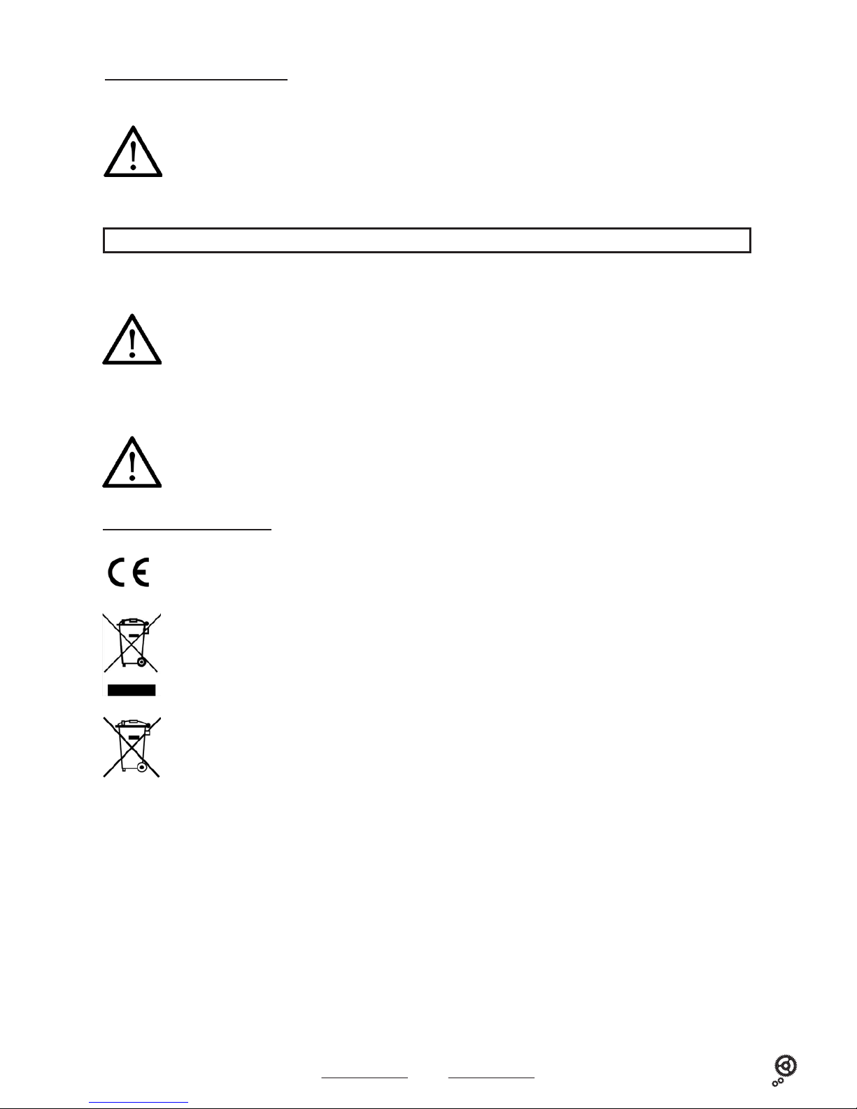
«CE» mark indicates that this product complies with the European requirements for safety, health, environment and customer protection.
This symbol (crossed-out wheeled bin WEEE Annex IV) indicates separate collection of waste electrical and electronic equipment in the EU countries.
Please do not throw the equipment into the domestic refuse. Please use the return and collection systems available in your country for the disposal
of this product.
This symbol (crossed-out wheeled bin Directive 2006/66/EC Annex II) indicates separate collection of waste batteries in the EU countries.
Please do not throw the batteries into the domestic refuse. Please use the return and collection systems available in your country for the disposal
of the waste batteries.
Registered trademarks :
Microsoft and Windows are registered trademarks by Microsoft Corporation.
Other registered marks (company name and product brands) belong to the said company.
WARNING !
HOROTEC© Flashtest operates only with a 9 V battery.
Do not use any other type of network adapters than those with your device.
Never heat or incinerate batteries. Take precautions when carrying or storing batteries to prevent them from coming into contact with any metal
objects such as jewellery, pins, fasteners, etc.
Never store batteries where they will be exposed to direct sunlight, or subjected to high temperatures in a hot vehicle, near a heat source, etc.
Never attempt to disassemble a battery or modify it in any way, solder, etc.
Keep always the batteries away from children.
CAUTION !
Always use only recommended batteries.
Keep the batteries dry at all times.
Do not use a battery if it is cracked or broken.
Never subject batteries to strong shocks or continuous vibrations.
Handling of the HOROTEC© Flashtest :
FOR OUR EUROPEAN CUSTOMERS :
Follow these important guidelines to prevent batteries from leaking overheating, burning, exploding, or causing electrical shocks or burns.
Page 18
18
10. CHARTER OF CONSUMPTION OF ELECTRONIC CIRCUITS / COILS RESISTANCE
ETA FE
Cal. μA. Ic μA. Mvt Coil kΩ Cal. μA. Ic μA. Mvt Coil kΩ
201001 0.35 1.20-1.60 5120-30 <0.30 0.40-0.80 1.50
205911 1.10 0.20-0.40 gen. 5820-6120 <0.30 0.40-0.80 1.50
210001-11 0.70 1.25-1.55 6130 <0.30 0.50-1.10 1.50
251252 3.10 6320 <0.30 0.40-0.80 1.50
1.00 set 70200-10 <0.40 0.60-1.40 1.20-1.40
5.80 chr 1.50-2.50 red 7021-22-24 <0.40 0.60-1.40 1.20-1.40
1.00-2.00 green 71200-20 <0.40 0.60-1.40 1.20-1.40
251262 3.20 7121-22 <0.40 0.60-1.40 1.20-1.40
0.50 set 7220B <0.40 0.60-1.40 1.20-1.40
5.80 chr 1.50-2.50 7221-22-28 <0.40 0.60-1.40 1.20-1.40
1.00-2.00 green 7224-34-44 <0.40 0.60-1.40 1.20-1.40
251265 4.60 73310 <0.40 0.60-1.40 1.20-1.40
2.50 set 7331-34-35 <0.40 0.60-1.40 1.20-1.40
7.20 chr 1.50-2.50 red 75210 <0.40 0.60-1.40 1.20-1.40
1.00-2.00 green 7524-29 <0.40 0.60-1.40 1.20-1.40
251272 1.50-2.50 red 7532-36-39 <0.40 0.60-1.40 1.20-1.40
1.00-2.00 green 7549-91-99 <0.40 0.60-1.40 1.20-1.40
251471 3.20
0.50 set ISA
5.80 chr 1.50-2.10 red
Cal. μA. Ic μA. Mvt Coil kΩ
1.20-1.80 green 1198 2.00
255111-22 0.50 1.50 3.50-4.00 120 0.90
255265 0.50 1.50 3.50-4.00 122-128 0.65
255411 0.50 1.50 3.50-4.00 125-127 0.38
255431-41 0.50 0.70 3.50-4.00 130-138 0.90
255461-81 0.50 1.50 3.50-4.00 257 0.40
255483 0.50 1.50 3.50-4.00 307-317 1.80
256031 0.40 0.75 1.30-1.60 317/103.05 2.40
256041 0.40 0.75 1.30-1.60 317/703 solar 1.00
256101-11 0.40 1.10 1.30-1.60 317/705 electrolum . 1.70
256461 0.45 1.20 1.80-2.00 320-321 1.00
280002 0.70 1.55-1.85 326-328 0.90
282001 0.50 1.20-1.50 326/168 small sec 1.20
551411 2.20 1.90-2.40 8153 2.35
555415 1.80 3.40-3.70 8154-61-62 1.70
555419 0.55 1.80 3.40-3.70 12.00 chr
579001 0.50 3.40-3.70 8155 2.35
579105 0.50 1.80 1.40-1.60 K62 0.35
802001 1.40 1.30-1.95 K63 1.70
802101 1.40 1.30-1.45 K63/302 ana digi 2.00
803111-21 1.40 1.20-1.40 K83 1.55
804111-21 1.40 1.20-1.60
805111-24 1.40 1.20-1.60
RONDA
805144 1.40 1.20-1.60
Cal. μA. Ic μA. Mvt Coil kΩ
901001-05 0.45 0.80-1.20 1062 0.35 2.70-2.90
902002-05 0.70 0.70 0.90-1.40 1063-64-65-60 0.72 2.70-2.90
902101 0.40 1.10 0.90-1.40 312 1.35-1.85 1.75-1.95
902105 0.40 1.10 0.90-1.40 312S 2.11-2.45 sec h 1.75-1.95
902501 0.40 1.10 0.90-1.40 2.63-2.95 sec
926301 1.80 2.00-3.00 315 1.35-1.85 1.75-1.95
955102-32 0.50 1.30 1.30-1.80 505-509 1.35-1.85 1.75-1.95
955402-12 0.50 1.30 1.30-1.80 515 2.11-2.45 sec h
955432 0.50 0.70 1.30-1.80 2.63-2.95 sec d 2.45-2.55
956114-24 0.35 1.35 3.70-4.10 519 2.11-2.45 sec h
956414 0.35 1.35 3.70-4.10 2.63-2.95 sec d 2.45-2.55
976001 0.60 2.10-2.40 705 0.85
978002 0.70 2.10-2.40 706-706.1 0.80-1.13 1.75-1.95
980003-05 0.50 0.60 1.45-1.75 706.B 1.65-1.85 1.75-1.95
980105-06 0.50 1.00 1.45-1.75 726 0.75
980108 0.50 1.00 1.45-1.75 3.95 chr 2.55-2.85
980153-63 0.50 1.00 1.45-1.75 751 0.40 2.65-2.90
E01001 0.50 0.90-1.20 753 0.71 2.65-2.90
E01401 0.50 0.90-1.20 762 0.40 2.65-2.90
G10211 3.60 763 0.71 2.65-2.90
6.60 chr 772-73-82-85 0.90 1.75-1.95
Page 19
19
SEIKO SEIKO
Cal. μA. Ic μA. Mvt Coil kΩ Cal. μA. Ic μA. Mvt Coil kΩ
IE20 - 0.30 1.60-2.80 V220 0.30 0.60 1.40-2.00
1F20 0.25 0.30 2.00-2.60 V33F 0.40 1.20 3.00-3.40
1N00 0.25 0.30 1.70-2.00 V33G 0.40 1.20 3.00-3.40
1N01 0.25 0.90 2.70-3.30 V33J 0.40 1.20 3.00-3.40
2A23 0.60 1.00 2.80-3.40 V400 0.30 0.50 2.00-2.40
2A27 0.60 1.10 2.30-2.80 V401 1.30 1.10 2.10-2.50
2C21 0.40 0.80 2.80-3.40 V421 - 2.20 1.50-1.90
2E20 0.30 0.60 1.40-2.00 V501 - 1.60 2F50 0.20 0.30 2.00-2.40 V506 - 1.60 2Y00 0.30 0.40 2.10-2.60 V507 - 2.30 3M22 0.40 0.80 2.40-3.20 V515 - 1.60 -
AG Coil 330-430 Ω V536 - 2.20 4N00 0.30 0.50 2.00-2.40 V537 - 2.20 4N01 0.30 1.10 2.10-2.50 V654 1.65 3.00 1.80-2.50
4N20 0.30 0.50 2.00-2.40 V655 1.65 3.00 1.80-2.50
5A50 - 0.30 1.80-2.60 V656 1.65 3.00 1.80-2.50
5M22 0.50 1.00 2.90-3.40 V657 1.65 3.00 1.80-2.50
gen. coil resist. V671 0.70 2.90 2.30-2.90
280 Ω-380 Ω V681 0.80 3.00 1.60-2.00 4002456
5M42 0.50 0.90 1.70-2.10 1.20-1.60 4002454
AG Coil new 1.90-2.30 V682 0.80 3.00 1.60-2.00 4002456
old 280-380 Ω 1.20-1.60 4002454
5M43 0.50 0.90 1.70-2.10 V69F 0.88 1.40 1.20-1.60
AG Coil new 1.90-2.30 V707 0.28 1.40 0.90-1.30
old 280-380 Ω V733 0.40 1.30 2.40-2.80
5T52 1.80 2.50 1.40-2.40 4002701-11 V736 0.40 1.30 2.40-2.80
1.70-2.30 4002700 V742 0.40 1.30 2.40-2.80
6M13 0.80 3.00 1.20-1.60 4002454 V743 0.40 1.30 2.40-2.80
0.80-1.20 4002455 V782 0.28 1.40 0.90-1.30
1.50-2.10 4002456 V789 0.28 1.40 0.90-1.30
6M15 0.80 3.00 1.20-1.60 4002454 V810 - 1.40 -
0.80-1.20 4002455 V827 - 1.60 -
1.50-2.10 4002456 VX32A - 1.85 -
6M23 0.80 3.00 1.20-1.60 4002454 VX39 - 1.20 -
0.80-1.20 4002455 VX82 - 1.10 -
1.50-2.10 4002456 VX89 - 1.10 -
6M26 0.80 3.00 1.20-1.60 4002454 W040 0.28 1.40 130-180Ω spk
0.80-1.20 4002455 W041 0.28 1.40 130-180Ω spk
1.50-2.10 4002456 W205 0.30 0.50 -
6M37 0.80 3.00 1.20-1.60 4002454 W206 0.50 0.70 -
0.80-1.20 4002455 W309 1.50 1.70 50-90Ω spk
1.50-2.10 4002456 W339 3.00 4.00 140-180Ω spk
7C17 0.30 1.50 2.00-2.50 W349 - 4.00 7C46 0.30 1.50 2.10-2.50 W357 3.00 4.00 50-90 Ω spk
7M22 0.50 1.50 1.70-2.40 W358 3.00 4.00 50-90 Ω spk
AG Coil 300-400 Ω W359 3.00 4.00 60-80 Ω spk
7N00 0.50 0.60 1.90-2.30 W620 - 4.40 7N01 0.40 1.30 2.40-2.80 W650 - 4.40 7N07 0.40 1.30 2.40-2.80 W680 - 5.50 7N08 0.40 1.30 2.40-2.80 W700 3.00 4.00 140-180 Ω spk
7N82-83 0.40 1.30 2.40-2.80 W800 - 5.00 125-175 Ω spk
7N85 0.40 1.30 2.40-2.80 W801 - 6.50 125-175 Ω spk
7N89 0.40 1.30 2.40-2.80 W802 - 4.00 125-175 Ω spk
7T27 1.80 2.50 1.20-1.60 4002711 W810 - 4.50 125-175 Ω spk
1.70-2.30 4002700 W820 - 4.00 125-175 Ω spk
7T32 1.80 2.50 Y121E - 1.90 -
10.00 chr 1.40-2.40 4002701-11 Y143 0.40 1.90 2.20-2.80
1.70-2.304002700 Y150 0.25 0.30 2.00-2.60
7T34 1.80 2.50 Y187 1.80 2.50
10.00 chr 1.40-2.40 4002701-11 10.00 chr 1.20-2.40 4002710-11
1.70-2.30 4002700 1.70-2.30 4002700
7T52 1.80 2.50 1.40-2.40 4002701-11 Y481 - 1.20 3.00-3.40
1.70-2.30 4002700 Y799 2.30 2.30 -
Page 20

20
CITIZEN MIYOTA
Cal. μA. Ic μA. Mvt Coil kΩ
Cal.
μA. Ic μA. Mvt Coil kΩ
0310 0.90 2.90-3.50 2025 1.30 2.80-3.40
0312 0.90 2.90-3.50 2033 1.30 2.80-3.40
0317 0.90 2.90-3.50 2034 1.30 2.80-3.40
0321 0.90 2.90-3.50 2035 1.30 2.80-3.40
0327 0.90 2.90-3.50 2036 1.30 2.80-3.40
0328 0.90 2.90-3.50 2039 1.30 2.80-3.40
0330 0.90 2.90-3.50 203A 1.30 2.80-3.40
0337 0.90 2.90-3.50 2045 1.30 2.89-3.40
0410 0.70 2.90-3.50 2105 1.50 1.90-2.40
0510 1.60 1.80-2.40 2115 1.50 1.90-2.40
1.80-2.30 sec chr 2115/6 1.50 1.90-2.40
0530 1.60 1.80-2.40 213D 1.50 1.90-2.40
1.80-2.30 sec chr 3S10/3H 3.00 0.80-1.30
0531 1.60 1.80-2.40 1.70-2.10
1.80-2.30 sec chr 2.40-3.00
0560 1.60 1.80-2.40 3S10/4H 3.00 0.80-1.30
2..0-2.50 1.70-2.10
0570 1.60 1.80-2.40 2.40-3.00
2.00-2.50 3S10/6H 3.00 0.80-1.30
0610 3.10 1.80-2.40 1.70-2.10
2.00-2.50 2.40-3.00
1.80-2.30 3S31 3.00 0.80-1.30
0730 0.90 1.90-2.30 1.70-2.10
0850 1.80 1.10-1.30 coil 1 2.40-3.00
1.90-2.30 coil 2-3 3S60 3.00 0.80-1.30
0855 1.80 1.10-1.30 coil 1 1.70-2.10
1.90-2.30 coil 2-3 2.40-3.00
0870 1.80 1.10-1.30 coil 1-3
1.90-2.30 coil 2
1002 0.90 1.20-1.70
INTERCHANGEABILITY SYSTEM BETWEEN
1012 0.90 1.20-1.70
CITIZEN AND MIYOTA CALIBRES
1020 0.90 1.50-1.90
1022 0.50 1.20-1.70
1030 0.90 1.50-1.90
MIYOTA CITIZEN
1102 0.90 1.20-1.70
1112 0.90 1.20-1.70 M = 0
2200 0.20 1.70-2.10 N = 1
2870 1.30 1.70-2.10 P = 2
2930 0.90 2.60-3.20 R = 4
3100 1.00 2.60-3.20 S = 5
3110 1.00 2.60-3.20 T = 6
3220 0.50 1.90-2.50 U = 7
3330 0.80 2.20-2.80 W = 8
3331 0.80 2.20-2.80 Y = 9
3570 3.00
1000 0.90 1.50-1.90
1010 0.90 1.50-1.90 Examples :
1032 0.90 1.50-1.90
1100 0.90 1.50-1.90 3510 = 3S10
2201A 0.20 1.70-2.10
2722 1.20 2.60-3.20 6870 = 6W70
2731 1.20 2.60-3.20
2854 1.20 2.90-3.50
3510 3.00 0.80-1.30
1.70-2.10
2.40-3.00
3531 3.00 0.80-1.30
1.70-2.10
2.40-3.00
0540 1.60 1.80-2.40
1.80-2.30 sec chr
2010 1.50 1.90-2.40
2000 1.50 1.90-2.40
USER.MSA19.115-EN
Version 1/Sept.2018
 Loading...