

Page 1
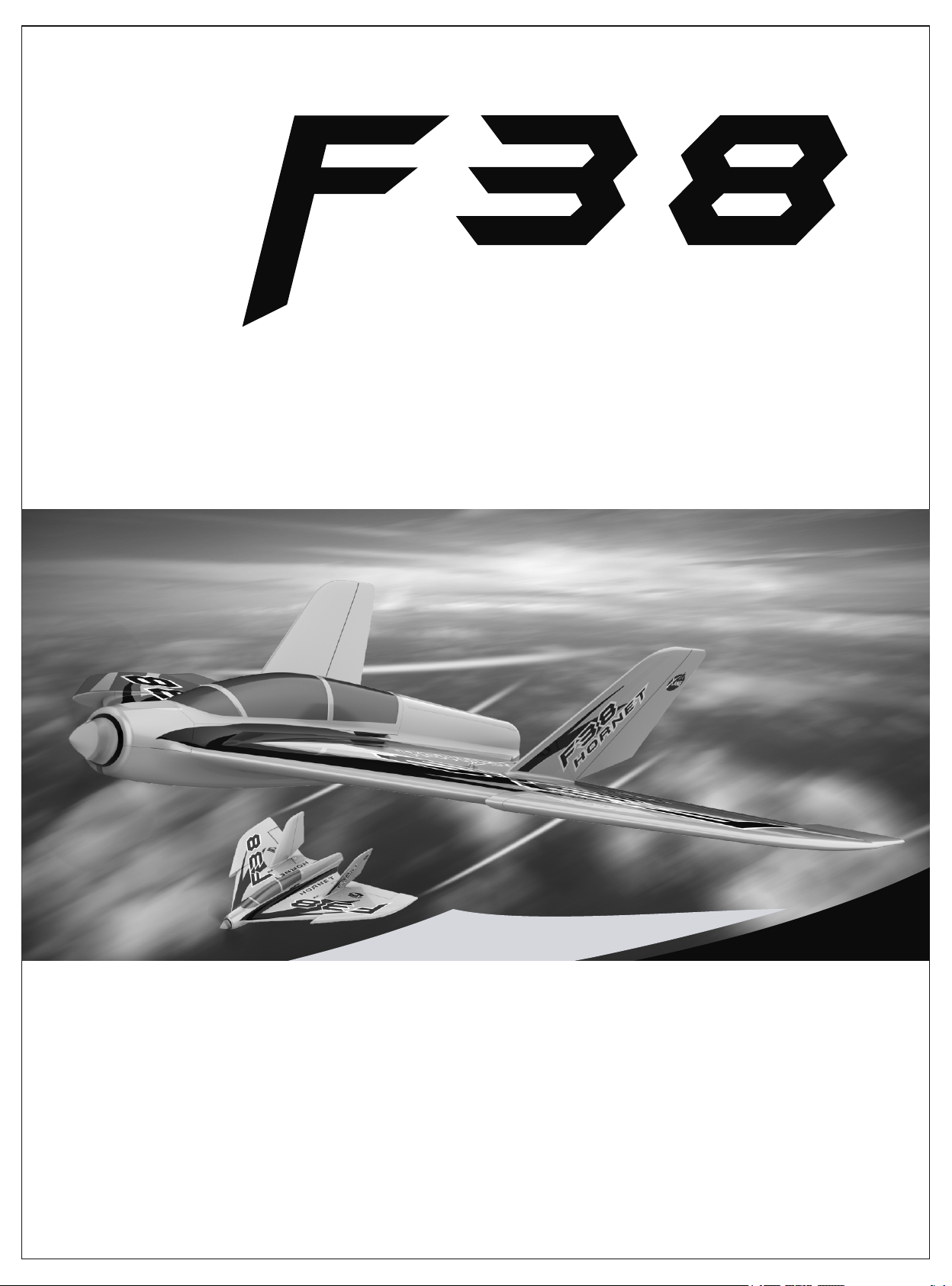
H O R N E T
VERSION 1
Wingspan:800mm/31.5in Length:550mm/21.7in Flying weight:560g/19.8oz
ASSEMBLY AND OPERATION
INSTRUCTIONS MANUAL
Page 2
F-38 HORNET
Thank you for purc ha si ng the new F38 HORNET from Xane.
Assembly for thi s ai rc raft is kept at a minimum.
This plane is powered by a brushless outr un ne r motor paired with a fact or y calibrated electronic spe ed
controller, ailerons control surfaces are controlled by servos; a ll of which are factory installed on t he
Ready-to-Fly version. If you have KIT version, this manual also will let you kn ow how to assembly it and
make the plane t o Re ad y- to-Fly version.
Please be sure to re ad t he e ntire manual carefully prior to assembling/operating the F38 Hornet.
Specification s
ITEM SPECIFICATIONS KIT ARF RTF
Motor: 2830-12 00 KV B rushless Motor
ESC
SERVO SERVO
RX
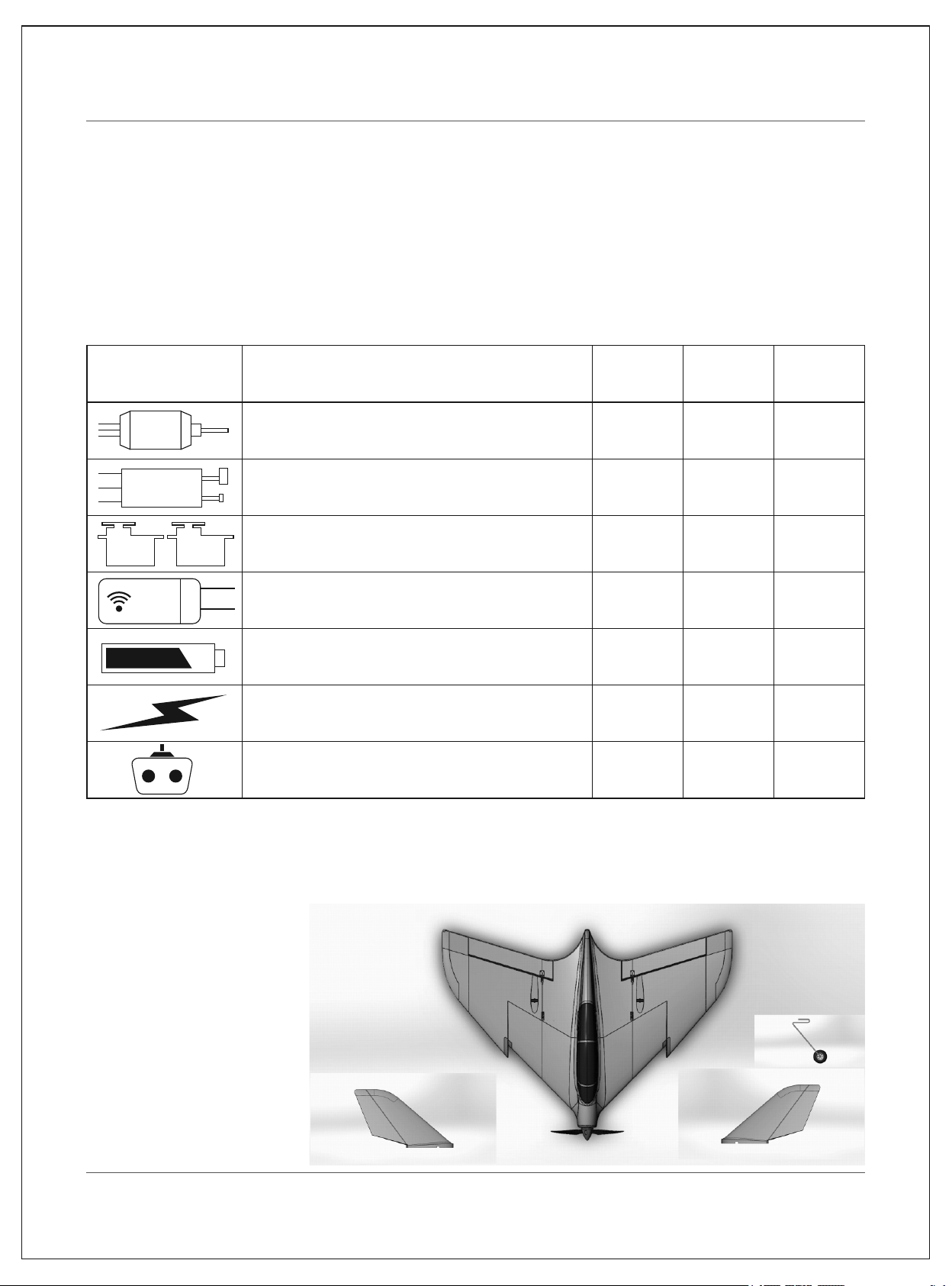
Package Conten ts
ARF(PNP) Vers io n
Ÿ Fuselage wit h fa ct or y installed motor, electronic speed controller and servos
Ÿ Vertical stab il iz er
Ÿ Landing gear
ESC: Hobbywing 3 0A sk y wa lker
Servo:9g servo 2 pc s
Receiver
Recommended ba tt er y:3S 2200-3200mah
Recommended ba tt er y ch arger:
3s Li-po balan ci ng c harger
Recommende d Tra ns mitter:
Full-Range 6 c ha nn el 2.4GHZ
N/A
N/A
N/A
N/A
N/A
N/A
N/A
Installed Installed
Installed Installed
Installed Installed
N/A
N/A
N/A
N/A
Installed
Installed
Installed
Installed
-02-
Page 3
F-38 HORNET
1. Before assemb li ng t he m odel
Please check the c on te nts of your kit before you start working on it.
You need :
Ÿ Servo-----2p cs
Ÿ Motor------2 83 0- 1200KV and 8×6 propellers
Ÿ ESC--------3 0A ho bb y wing
2. Preparation
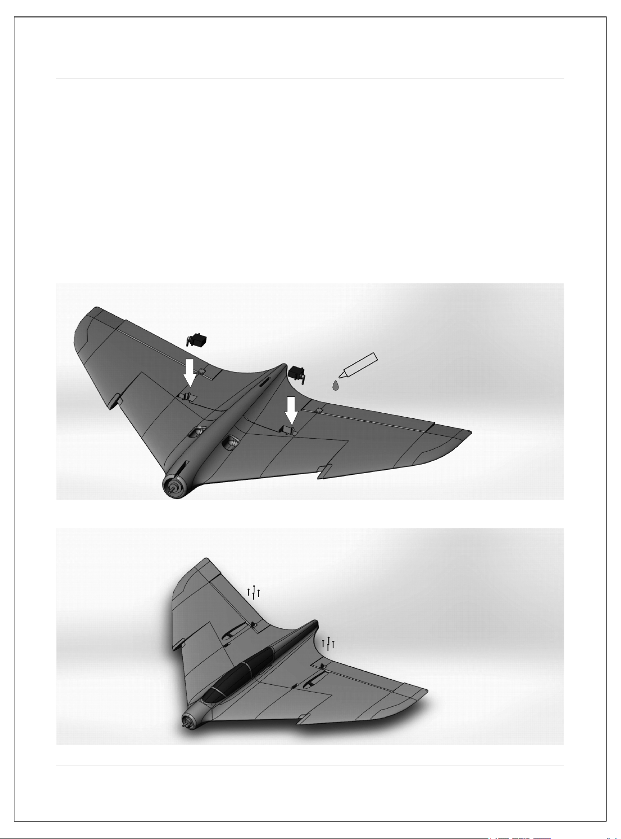
Fig. 1 Main wing panel.
Ÿ Apply adhesi ve ( no t included) to the servo holes, and then located the servo into the hole.
Ÿ Install the cont ro l ho rns with screw.
-03-
Page 4

F-38 HORNET
Fig. 2 Main wing panel.
Ÿ Adjusting th e Cl ev is
Ÿ Turn the clevis (A) clockwise or counterclockwise on the linkage.
Ÿ Carefully sp re ad t he c levis and put the clevis pin (B) in a selected hole in the control horn (C).
Ÿ Connect the pu sh r od w ith servo arm and control horns
Ÿ Verify the contro l su rf ace tips are mechanically centered.
A
B
C
First Hole
-04-
Page 5

Fig. 3 Assembly the tail wing.
Ÿ Apply adhesi ve (n ot include) to the Vertical fin and then glued with fuselage.
F-38 HORNET
Fig. 4 Assembly the propellers.
-05-
Page 6

F-38 HORNET
Fig. 5 Assembly the landing gear.
Ÿ Push the landi ng g ea r into the hole of the plastic set.
Then the plane w er e as sembled finished.
3. Assembly the receiver and battery
3.1 Receiver ins ta ll ation
Ÿ The receiver h as to be installed further aft in t he fuselage. Check that the c ab le s are long enough to
allow the plugs and sockets to the connected outside the fuselage. The speed controller can be
secured in the s pa ce u nder the canopy.
Ÿ Connect the le ft s er vo t o CH1, right servo to CH2,Speed controller to CH3
CH6
CH5
CH4
RX
CH3
CH2
CH1
SPEED CONTROLL ER
RIGHT AILERON SERVO
LEFT AILERON SERVO
-06-
Page 7

F-38 HORNET
3.2 Battery inst al la tion
Ÿ Install the battery in the model as below pic,and
fixe d the bat tery with loop stra ps, this is very
import,becau se this plane is an high p er fo rmance
Acr o mod el,L oose bat tery may be c rash ed t he
plane.
Fig. 1 LiPo charging ins tr uc tions
Ÿ Charge the LiPo battery by connecting the wall socket
adapter (not included) to the balance charger. W he n power
is supplied to the balan ce charger, connect the charge lead
(usually whi te ) of t he L iPo battery to the balance charger.
Ÿ Always supervise charger while in use and avo id charging
battery for extended periods of time (keep charge time
under 1 hour and 3 0 mi nu tes).
4. Checking the powe r sy st em.
Ÿ Power on the transmitter wi th the throttle s ti ck and trim at the “LOWEST” position th en power up the
aircraft.
Ÿ Hold the aircr af t se cu rely.
Ÿ Remove any loo se o bj ects such as cloths, tools, etc from the area in front of the model.
Ÿ Open the throttle (stick fo rw ar d): the motor should now run and you should feel a stro ng air flow rushing
out from propel le r. Please do not bench test the unit for more than 10 seconds as there is no flowing air
to cool the unit.
Ÿ Move the throttl e st ic k back to the “LOWEST” position.
Ÿ Move the Eleva to r th e pl ane will pitch up or pitch down.
Ÿ Move the Ailero n th e pl ane will roll right or roll left.
Ÿ Disconnect t he b at te ry from the electronic speed controller and then switch the transmitter off.
Ÿ After assembly a nd t ra nsmitter set up,confirm that the control surfaces are centered
1, Verify the trims a nd s ub tr ims on your transmitter are 0
2, Power up the mode l an d le ave the throttle at 0
3, Verify the contr ol s ur fa ce tips are mechanically centered.
4, If you need to mak e an adjustment,rotate the clevis on the linkage to alter the linkage between the
servo and the co nt ro l ho rn.
Dual Rates
Ail(Low Rate)
Adjust the rudder su rf ac e to horizontal standard
Low Rate
8mm
8mm
Ele(Low Rate)
8mm
8mm
Ail
Ele
12mm
12mm
Ail(Hi Rate)
8mm
8mm
Hi Rage
12mm
12mm
12mm
12mm
Ele(Hi Rate)
-07-
Page 8

F-38 HORNET
5. Checking the mo de l’s balance.
Ÿ Place the fligh t ba tt er y in its compartment without connecting.
Ÿ Mark the centre of g ra vi ty (CG) on both sides of the fuselage; the position is shown in the photo.
Ÿ Support the model at the marked points and allow it to hang freely. Wh en correctly bala nc ed the
airplane wil l re ma in horizontal with the nose slightly down.
Ÿ If necessary, adjust the position of the flight batter y to a ch ie ve the correct CG.
Ÿ Mark the battery location in the fuselage, so that you can be sure of positioning it correctly after
recharging .
Ÿ Charge the flig ht b at te ry and the model is ready for flight.
15°
200-210mm
Test flying – Notes on flying the airplane.
Ÿ For the first flight y ou s ho uld wait for a relatively calm day with no more than a gentle breeze.
Ÿ A good flying s it e is a large, flat, ope n field; well away from tre es , fences, high-tension overhead cables
and other pote nt ia lly dangerous obstacles.
Ÿ Carry out a comple te c he ck of the working systems.
Ÿ All control su rf ac es r espond correctly.
Ÿ Adequate thr ot tl e re sponse and battery voltage.
Ÿ Perform a range ch ec k if h aven’t already.
Ÿ We recommend that you ask an experienced mo de le r to help you initially; to gi ve the model a fairly
powerful han d- la unch.
Ÿ The model must be la un ch ed directly into any existing wind.
Ÿ Switch the motor o n, a nd l aunch the airplane strongly into the wind with the fuselage and wings leveled.
Ÿ Allow the F38 to fly st ra ig ht and level initially; don’t try to turn it when it is close to the ground.
Ÿ Adjust the trims i f ne ce ssary so that the model settles into a steady climb.
Ÿ Check th e model’s re sponse to control commands from the transmitter. You may need to increase or
reduce the con tr ol s ur face travels once the model is back on the ground.
Ÿ Take the airplan e up t o a sa fe h eight and check its stalling speed.
Ÿ Keep the speed w el l up o n the landing approach to avoid stalling.
Ÿ If you had to move the trims during the flight, correct the mechanical linkages be fo re flying again. T hi s
allows you to re -c en tr e the trims, so that full trim travel is available for subsequent flights.
-08-
 Loading...