

Page 1
MAN0868-04-EN Specifications / Installation
/
r
1 Specifications
HE-XT100 / HEXT240C000
Specifications
Required
Power
(Steady State)
Required
Power (Inrush)
Primary Power
Range
Relative
Humidity
Clock Accuracy +/- Seven Minutes/Month at 20C
Operating
Temperature
Terminal Type Screw Type, 5 mm Removable
Weight 12 oz. (340.19 g)
CE
UL
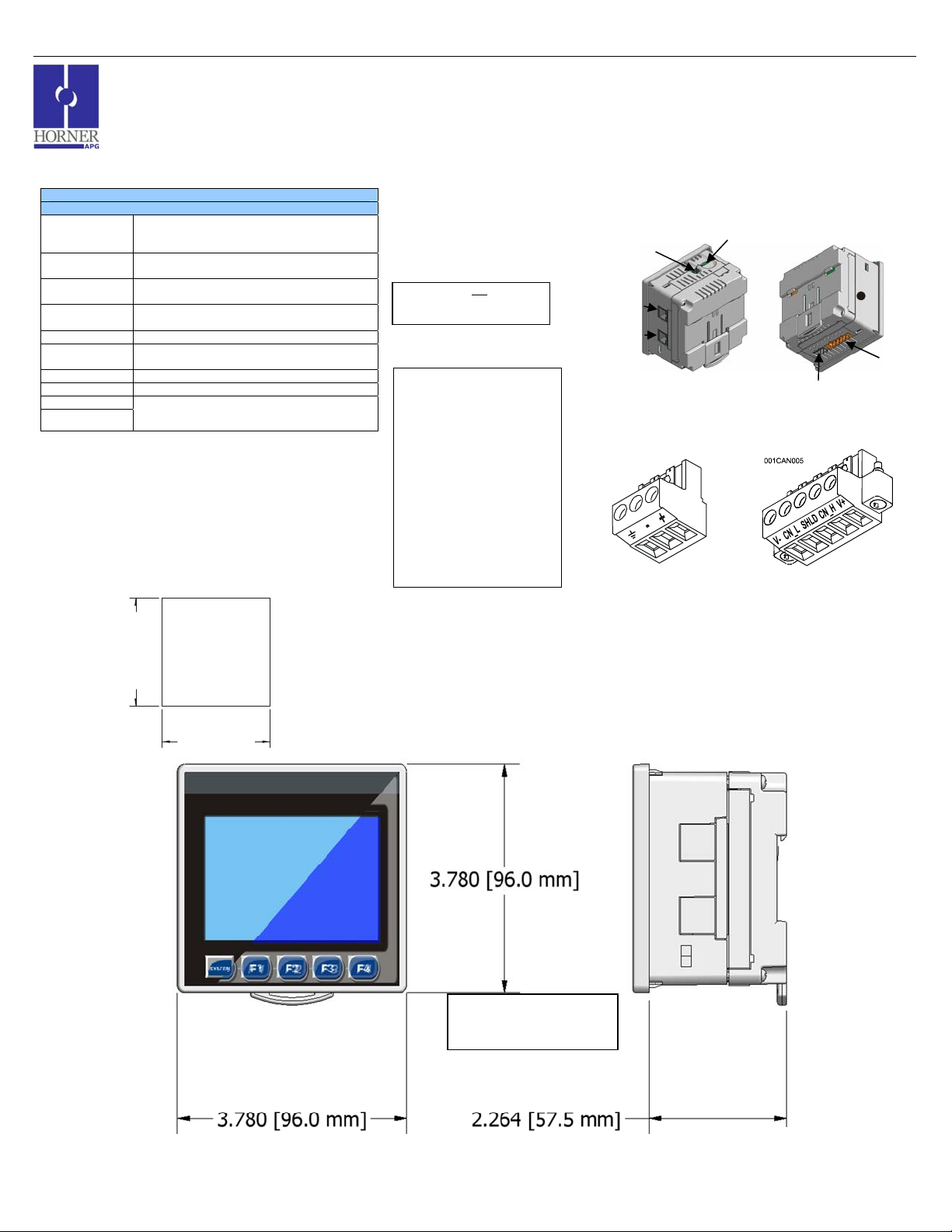
2 Panel Cut-Out and Dimensions
General Specifications
130 mA @ 24 VDC
30 A for 1 ms @ 24 VDC
10 – 30 VDC
5 to 95% Non-condensing
-10°C to +60°C
See Compliance Table at :
http://www.heapg.com/Support/compliance.htm
Note: Max. panel thickness: 5 mm.
Refer to the User Manual for panel box information and a handy
checklist of requirements.
Note: The tolerance to meet NEMA standards is ± 0.005” (0.1 mm).
3.622 [92mm]
3.622 [92mm]
001XLE002
XLt OCS Model:
3 Ports / Connectors / Cables
Note: The case of the XLt is black, but for clarity, it is shown in a lighter gray color.
HEXT240C100
To Remove Back Cover:
Unscrew 4 screws located on
the back of the unit and remove
CAUTION: Do notover tighten
back cover.
screws when replacing back
cover.
Memory Slot:
Uses Removable Memory for
data logging, screen captures,
program loading and recipes.
Horner Part No.: HE-MC1
Serial Communications:
MJ1: (RS-232 / RS-485) Use for
Cscape programming and
Application-Defined
Communications.
MJ2: (RS-232 / RS-485) Use for
Application-Defined
Communications.
(RS-232 / RS-485)
(RS-232 / RS-485)
DIP
Switch
MJ2
MJ1
Power Connector
Power Up:
Connect to Earth Ground.
Apply 10 - 30 VDC.
Screen lights up.
Torque rating 4.5 – 7 Lb-In
(0.50 – 0.78 N-m)
Memory Slot
Use the CAN Connector when
using CsCAN network.
Torque rating 4.5 – 7 Lb-In
Powe
CAN Connector
(0.50 – 0.78 N-m)
NET 1
(CsCAN)
Note – Your keypad overlay
appearance may differ. Standard
US/EU overlays pictured here for
example.
__________________________________________________________________________________________________________________________________________________________________
12/19/2008 Page 1 of 3 ECN # 947
Page 2
MAN0868-04-EN Specifications / Installation
g
A
A
8
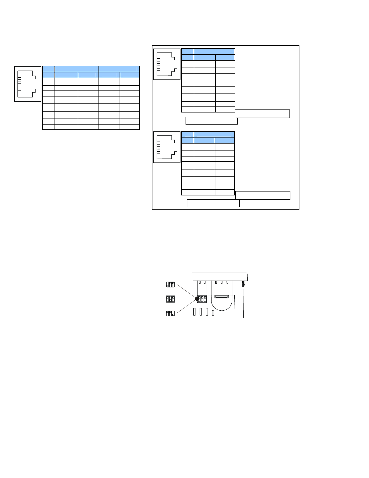
4 Serial Communications:
MJ1: (RS-232 / RS-485) Use for Cscape programming and
pplication-Defined Communications.
MJ2: (RS-232 / RS-485) Use for Application-Defined
Communications.
8
1
Pin MJ1 Pins MJ2 Pins
Signal Direction Signal Direction
TXD OUT TXD OUT
8
RXD IN RXD IN
7
0 V Ground 0 V Ground
6
+5 60mA OUT +5 60mA OUT
5*
RTS OUT TX- OUT
4
CTS IN TX+ OUT
3
RX- / TX- IN / OUT RX- IN
2
RX+ / TX+ IN / OUT RX+ IN
1
5 Wiring and Jumpers
Wire according to the type of inputs / outputs used, and select the
appropriate jumper option.
• Use Only Copper Conductors in Field Wiring, 60/75° C
Wiring Specifications
For CAN wiring, use the
following wire type or equivalent:
Belden 3084, 24 AWG (0.2 mm
er.
or lar
2
)
5.1 External DIP Switch Settings
s seen when looking at the top of the XLt unit:
The DIP Switches are used for
termination of the RS-485 ports. The
XLt is shipped un-terminated.
To terminate, select one of the DIP
Switches and configure it based upon
the option that is desired.
DIPSW3: FACTORY USE ONLY (tiny
bootloader firmware downloading). NOT
TO BE USED FOR NORMAL OCS
OPERATION.
DIPSW2: MJ2 Termination
(Default – none)
DIPSW1: MJ1 Termination
(Default – none)
6 MJ2 Pinouts in Half and Full Duplex Modes
1
8
1
Pin MJ2 Pins
Signal Direction
TXD OUT
8
RXD IN
7
0 V Ground
6
+5 60mA OUT
5*
TX- OUT
4
TX+ OUT
3
TX-/RX- IN/OUT
2
TX+/RX+ IN/OUT
1
MJ2 Half Duplex Mode
Pin MJ2 Pins
Signal Direction
TXD OUT
8
RXD IN
7
0 V Ground
6
+5 60mA OUT
5*
TX- OUT
4
TX+ OUT
3
RX- IN
2
RX+ IN
1
MJ2 Full Duplex Mode
* +5Vdc 60mA Max
* +5Vdc 60mA Max
001XLE037-R1
__________________________________________________________________________________________________________________________________________________________________
12/19/2008 Page 2 of 3 ECN # 947
Page 3
MAN0868-04-EN Specifications / Installation
7 Safety
When found on the product, the following symbols specify:
8 Technical Support
Warning: Electrical
Shock Hazard.
This equipment is suitable for use in Class I, Division 2, Groups A, B, C and D or Non-hazardous locations only
WARNING – EXPLOSION HAZARD – Substitution of components may impair suitability for Class I, Division 2
AVERTISSEMENT - RISQUE D'EXPLOSION - LA SUBSTITUTION DE COMPOSANTS PEUT RENDRE CE MATERIAL INACCEPTABLE POUR LES EMPLACEMENTS DE
CLASSE 1, DIVISION 2
WARNING – EXPLOSION HAZARD – Do not disconnect equipment unless power has been switched off or the area is known to be non-hazardous.
AVERTISSEMENT - RISQUE D'EXPLOSION - AVANT DE DECONNECTOR L'EQUIPMENT, COUPER LE COURANT OU S'ASSURER QUE L'EMPLACEMENT EST DESIGNE
NON DANGEREUX.
WARNING: To avoid the risk of electric shock or burns, always connect the safety (or earth) ground before making any other connections.
WARNING: To reduce the risk of fire, electrical shock, or physical injury it is strongly recommended to fuse the voltage measurement inputs. Be sure to locate fuses as close to
the source as possible.
WARNING: Replace fuse with the same type and rating to provide protection against risk of fire and shock hazards.
WARNING: In the event of repeated failure, do not
WARNING: Only qualified electrical personnel familiar with the construction and operation of this equipment and the hazards involved should install, adjust, operate, or service
this equipment. Read and understand this manual and other applicable manuals in their entirety before proceeding. Failure to observe this precaution could result in severe bodily
injury or loss of life.
This device complies with part 15 of the FCC Rules. Operation is subject to the following two conditions:
1. This device may not cause harmful interference.
2. This device must accept any interference received, including interference that may cause undesired operation.
Warning: Consult
user documentation.
replace the fuse again as a repeated failure indicates a defective condition that will not clear by replacing the fuse.
All applicable codes and standards need to be followed in the installation of this product.
Adhere to the following safety precautions whenever any type of connection is made to the module:
Connect the safety (earth) ground on the power connector first before making any other connections.
When connecting to electric circuits or pulse-initiating equipment, open their related breakers.
Do not
make connections to live power lines.
Make connections to the module first; then connect to the circuit to be monitored.
Route power wires in a safe manner in accordance with good practice and local codes.
Wear proper personal protective equipment including safety glasses and insulated gloves when making connections to power circuits.
Ensure hands, shoes, and floor are dry before making any connection to a power line.
Make sure the unit is turned OFF before making connection to terminals.
Make sure all circuits are de-energized before making connections.
Before each use, inspect all cables for breaks or cracks in the insulation. Replace immediately if defective.
For assistance and manual updates, contact Technical Support at the following locations:
North America:
(317) 916-4274
http://www.heapg.com
email: techsppt@heapg.com
No part of this publication may be reproduced without the prior agreement and written permission of Horner APG, Inc. Information in this document is subject to change w ithout notice .
Europe:
(+) 353-21-4321-266
http://www.horner-apg.com
email: techsupport@hornerirl.ie
__________________________________________________________________________________________________________________________________________________________________
12/19/2008 Page 3 of 3 ECN # 947
 Loading...