

Page 1
MAN0887-05-EN Specifications / Installation
Max Thermocouple Error
HE-XL105 / HE-XL1M5 / HEXT350C115 / HEXT280C115
XL6/XL6M/XL6e OCS Models
HE-XL1E5 / HEXT351C115
12 Digital DC Inputs / 12 Digital DC Outputs
2 Analog Inputs (High Resolution) / 2 Analog Outputs
1 Specifications
Inputs per Module 12 including 4 configurable HSC inputs Outputs per Module 12 including 2 configurable PWM outputs
Commons per Module 1 Commons per Module 1
Input Voltage Range 12 VDC / 24 VDC Output Type Sourcing / 10 K Pull-Down
Absolute Max. Voltage 35 VDC Max. Absolute Max. Voltage 28 VDC Max.
Input Impedance
Input Current Positive Logic Negative Logic Max. Output Current per point 0.5 A
Upper Threshold 0.8 mA -1.6 mA Max. Total Current 4 A Continuous
Lower Threshold 0.3 mA -2.1 mA Max. Output Supply Voltage 30 VDC
Max Upper Threshold 8 VDC Minimum Output Supply Voltage 10 VDC
Min Lower Threshold 3 VDC Max. Voltage Drop at Rated Current 0.25 VDC
OFF to ON Response 1 ms Max. Inrush Current 650 mA per channel
ON to OFF Response 1 ms Min. Load None
HSC Max. Switching Rate
Number of Channels 2 Thermocouple Temperature Range
Input Ranges
(Selectable)
Safe input voltage range
Nominal Resolution
Input Impedance
(Clamped @ -0.5 VDC to 12
VDC)
%AI full scale
Max. Over-Current 35 mA Conversion Time per Channel
Open Thermocouple Detect
Current
Number of Channels 2
Output Ranges
Nominal Resolution 12 Bits Primary Power Range 10 - 30 VDC
Update rate Once per PLC scan Operating Temperature
Minimum 10 V load
Maximum 20 mA load
Analog Outputs;
Output Points Required
Maximum Error at 25°C (excluding
zero)
Additional error for temperatures
other than 25°C
Display Life
User Keys
Screens supported 1023 Display Screen Dimension 320 x 240
Colors
__________________________________________________________________________________________________________________________________________________________________
3/2/2010 Page 1 of 8 #1037
Digital DC Inputs Digital DC Outputs
10 kΩ
10 kHz Totalizer/Pulse, Edges
5 kHz Frequency/Pulse, Width
2.5 kHz Quadrature
0 - 10 VDC
0 – 20 mA
4 – 20 mA
100mV
PT100 RTD,
and J, K, N, T, E, R, S, B Thermocouples
10 VDC: -0.5 V to +15 V
20 mA: -0.5 V to +6 V
RTD / T/C: ±24 VDC
10V, 20mA, 100mV: 14 Bits
RTD, Thermocouple: 16 Bits
Current Mode:
100 Ω, 35mA Max. Continuous
Voltage Mode:
500 kΩ, 35mA Max. Continuous
10 V, 20 mA, 100 mV: 32,000 counts full scale.
RTD / T/C: 20 counts / °C
50 nA RTD Excitation Current
Analog Outputs General Specifications
0-10 VDC,
0-20 mA
1 kΩ
500 Ω
2 Filtering
0.1%
0.01% / °C
Clock Accuracy
Minimum 40000 hours (50%
brightness, 25 deg C)
5 user-defined Function keys and
a System Key
32768/ 16 shade Grey scale
(XL6M models only)
Specifications
Output Protection Short Circuit
OFF to ON Response 1 ms
ON to OFF Response 1 ms
Analog Inputs, High Resolution
Required Power
(Steady State)
Required Power (Inrush)
Storage Temperature 14 to 140°F (-10 to 60°C)
Relative Humidity 5 to 95% Non-condensing
Terminal Type Screw Type,5 mm Removable
Display Memory 2.75 MB
Output Characteristics Current Sourcing (Positive Logic)
B / R / S
E
T
J
K / N
Thermocouple Common Mode Range ±10V
Converter Type Delta Sigma
Max. Error at 25°C
(*excluding zero)
(After Warm Up Time of One Hour)
Conversion Speed, Both Channels
Weight 26.5 oz. (0.751kg)
CE
UL
Display Properties
Display Type 5.7” QVGA TFT
Display Size 5.7”
Converted
USA: http://www.heapg.com/Pages/TechSupport/ProductCert.html
Europe: http://www.horner-apg.com/en/support/ certification.aspx
+/- 35 ppm maximum at 25° C (+/- 1.53 Minutes per Month)
2912°F to 32.0°F (1600°C to 0°C)
1652°F to -328°F (900°C to -200°C)
752.0°F to -400.0°F (400°C to -240°C)
1382.0°F to -346.0°F (750°C to -210°C)
2498.0°F to -400°F (1370°C to -240°C)
*4-20 mA ±0.10%*
*0-20 mA ±0.10%*
*0-10 VDC ±0.10%*
RTD (PT100) ±1.0 °C
0-100 mV ±0.05%
±0.2% (±0.3% below -100°C)
10V, 20mA, 100mV: 30 Times/Second
RTD, Thermocouple: 7.5 Times/Second
10V, 20mA, 100mV: 16.7mS
RTD, Thermocouple: 66.7mS
500 mA @ 24 VDC
30 A for 1 ms @ 24 VDC – DC Switched
2.5 A for 4 ms @ 24 VDC - AC Switched
-10° to 60° Celsius
15Hz hash (noise) filter
1-128 scan digital running average filter
250 µA
Page 2
MAN0887-05-EN Specifications / Installation
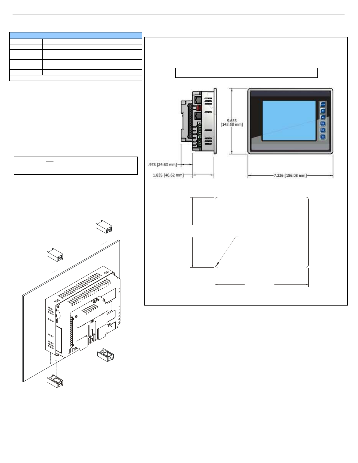
Caution: Do
not
force the OCS into the panel cutout.
6.875”
001OCS003-R1
001XLQX007
Connectivity
Serial Ports 2 Serial Ports – RS232 & RS485
Ethernet 10/100-Mbps (XL6e models only)
USB
Removable
Media
Smartstix Remote IO modules communicating on CAN
Note: Highest usable frequency for PWM output is 65 KHz
USB Networking Port for communication with PCs
and programming Port
Removable Media for upto 2 GB of storage for
programs, data logging or screen capture
3 Panel Cut-Out and Dimensions
Note: Max. panel thickness: 5 mm.
Refer to the XL6 User Manual (MAN0883) for panel box information and a handy checklist of requirements.
Note: The tolerance to meet NEMA standards is ± 0.005” (0.1 mm).
2 Installation
1. Prior to mounting, observe requirements for the panel layout
design and spacing/clearances in the OCS XL Series Manual
(MAN0883).
2. Cut the host panel.
3. Insert the OCS through the panel cutout (from the front). The
gasket material needs to be between the host panel and the
OCS.
An incorrectly sized panel cutout can damage the
4. Install and tighten the mounting clips (provided with the OCS) until
the gasket material forms a tight seal.
5. Connect cables as needed such as communications,
programming, power and CsCAN cables to the ports using the
provided connectors.
6. Begin configuration procedures.
touch screen.
5.156”
[131mm]
R .125” [3 mm] TYP.
RADIUS CORNERS
WHEN REQUIRING
DUST OR WATER
TIGHT SEAL PER
NEMA 4, 4X OR 12
[175mm]
__________________________________________________________________________________________________________________________________________________________________
3/2/2010 Page 2 of 8 #1037
Page 3
MAN0887-05-EN Specifications / Installation
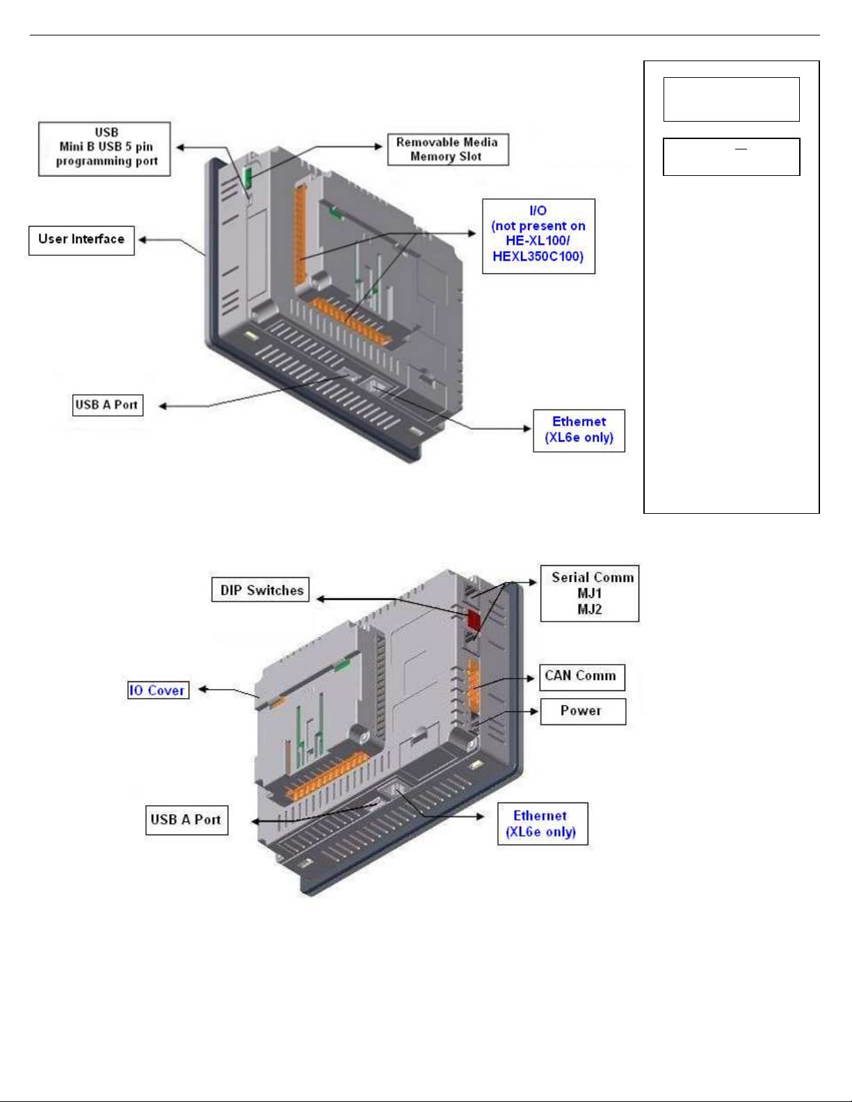
Remove cover.
CAUTION:
d internally.
4 Ports and Connectors
To Remove I/O Cover:
Unscrew 4 screws located on the
cover.
screws when replacing the back
I/O Jumpers (JP) are locate
To access, remove I/O cover of unit.
Wiring Connectors (J1 / J2 / J3) and
I/O Jumpers (JP1 / JP2 / JP3 / JP4)
are described in the Wiring and
Jumpers section of this document.
USBA: For flash drive connectivity
USBB: For network communication and
programming of OCS
Removable Media:
Uses Removable Memory for data
logging, screen captures, program
loading and recipes. Horner Part No.:
HE-MC1
Serial Communications: MJ1/MJ2:
(RS-232 / RS-485) Use for Cscape
programming and Application-Defined
Communications.
Ethernet: Used for Cscape
programming and Application-Defined
Communications.
Do not over tighten
cover.
I/O Jumpers:
__________________________________________________________________________________________________________________________________________________________________
3/2/2010 Page 3 of 8 #1037
Page 4

MAN0887-05-EN Specifications / Installation
As seen when looking at the side of the XL6 unit :
The DIP Switches are used for
485 ports. The
To terminate, select one of the DIP
Switches and configure it based upon
1
8
1
8
1
8
Off
Off
Off
4.1 Serial Communications
MJ1: (RS-232 / RS-485) Use for Cscape programming
and Application-Defined Communications.
MJ2: (RS-232 / RS-485) Use for Application-Defined
Communications.
Pin
MJ1 Pins MJ2 Pins
Signal Direction Signal Direction
TXD OUT TXD OUT
8
RXD IN RXD IN
7
0 V Ground 0 V Ground
6
+5 60mA OUT +5 60mA OUT
5*
RTS OUT TX- OUT
4
CTS IN TX+ OUT
3
RX- / TX- IN / OUT RX- IN
2
RX+ / TX+ IN / OUT RX+ IN
1
Table - Ports and Functions
Functions Port 1 (MJ1) Port 2 (MJ2)
RS-232
Hardware Handshaking
Programming
Ladder function
controlled
Serial Downloable
Protocols
RS 485 Full duplex
X
X
X
RS485 Half duplex
4.2 External DIP Switch Settings
MJ2 Pinouts in Half and Full Duplex Modes
Pin
MJ2 Pins
Signal Direction
TXD OUT
8
RXD IN
7
0 V Ground
6
+5 60mA OUT
5*
TX- OUT
4
TX+ OUT
3
TX-/RX- IN/OUT
2
TX+/RX+ IN/OUT
1
MJ2 Half Duplex Mode
Pin
MJ2 Pins
Signal Direction
TXD OUT
8
RXD IN
7
0 V Ground
6
+5 60mA OUT
5*
TX- OUT
4
TX+ OUT
3
RX- IN
2
RX+ IN
1
MJ2 Full Duplex Mode
* +5V 60mA Max
* +5V 60mA Max
termination of the RSXL6 is shipped un-terminated.
the option that is desired.
On
On
On
MJ1
SW1 - ON enables MJ2 RS485 port termination (121 Ohms).
OFF disables MJ2 RS485 port termination.
SW2 & SW3 - ON places MJ2 RS485 port in half-duplex mode.
OFF places MJ2 RS485 port in full-duplex mode.
SW4 - ON enables MJ1 RS485 port termination (121 Ohms).
OFF disables MJ1 RS485 port termination.
MJ2
__________________________________________________________________________________________________________________________________________________________________
3/2/2010 Page 4 of 8 #1037
Page 5

MAN0887-05-EN Specifications / Installation
001XLE036
r I/O wiring (discrete), use the
following wire type or equivalent:
)
ollowing wire type or equivalent:
)
Analog In Settings
T2
T2
JP3
10V/20mA
MA1/V1
MA2/V2
J2
J3
JP2
JP1
JP4
001XLE030
Location of I/O jumpers (JP)
JP4
4.3 CAN Network Port and Wiring
CAN Connector
Use the CAN Connector when
using CsCAN network.
Torque rating 4.5 – 7 Lb-In
(0.50 – 0.78 N-m)
NET1 Port Pin Assignments
Pin Signal Signal Description Direction
1 V- CAN Ground
−
2 CN_L CAN Data Low In/Out
3 SHLD Shield Ground
−
4 CN_H CAN Data High In/Out
5 NC No Connect
−
4.4 Ethernet Port
Speeds 10 BaseT Ethernet (10-Mbps)
100 BaseTx Fast Ethernet (100-Mbps)
Modes Half or Full Duplex
Auto-Negotiation Both 10/100-Mbps and Half/Full Duplex
Connector Type Shielded RJ-45
Cable Type
(Recommended)
CAT5 (or better) UTP
Port Auto MDI/MDI-X
4.5 Power Port and Wiring
Power Connector
Power Up:
Connect to Earth Ground.
Apply 10 - 30 VDC.
Screen lights up.
Torque rating 4.5 – 7 Lb-In
(0.50 – 0.78 N-m)
5 Wiring and Jumpers
• Wire according to the type of inputs / outputs used and select the appropriate jumper option.
• Use Copper Conductors in Field Wiring Only, 60/75° C
5.1 I/O Jumpers Settings (JP1 – JP4)
Note: The Cscape Module Setup configuration must match the selected I/O (JP) jumper settings.
Note: When using JP4 (output) or JP2 / JP3
(inputs), each channel can be independently
configured. For example, JP2 can be configured
for 10 V and JP3 can be configured as an RTD.
Wiring Specifications
Fo
Belden 9918, 18 AWG (0.8 mm
or larger.
For shielded Analog I/O wiring,
use the following wire type or
equivalent: Belden 8441, 18
AWG (0.8 mm2) or larger.
For CAN wiring, use the
f
Belden 3084, 24 AWG (0.2 mm
or larger.
Positive Logic vs. Negative Logic Wiring
The XL6 can be wired for Positive Logic inputs or
12-24VDC
Positive Logic In Negative Logic In
ANALOG OUTPUT SETTING
VOLTAGE OR CURRENT
CURRENT
(20mA)
AQ2 AQ1
Default
JP1 Digital DC Inputs
Positive Logic
Default
VOLTAGE
(10V)
AQ2 AQ1
Negative Logic
2
J1
2
Negative Logic inputs.
I1
0V
and wiring connectors
(J1 – J3).
JP3
I1
0V
JP2 and JP3
AI1 AI2
T/C/100mV
JP2
T1
RTD (PT100)
JP2
T1
JP2
Default
JP3
JP3
Primary Power Port Pins
Pin Signal Description
1 Ground Frame Ground
2 V- Input Power Supply Ground
3 V+ Input Power Supply Voltage
__________________________________________________________________________________________________________________________________________________________________
3/2/2010 Page 5 of 8 #1037
Page 6

MAN0887-05-EN Specifications / Installation
mV In
0 V
as shown for proper
Q10
Q11
Q12
V+
0V
LOAD
LOAD
LOAD
LOAD
LOAD
LOAD
LOAD
LOAD
LOAD
LOAD
LOAD
10 - 30VDC
NC
001XLE008
*
AQ1 and AQ2 are referenced as
5.2 Wiring Examples
J1
Orange
I1 IN1
I2 IN2
I3 IN3
I4 IN4
I5 IN5
I6 IN6
I7 IN7
I8 IN8
H1
H2
H3
H4
NC
NC
0V Ground
J3
Orange
T1+
T1-
T2+
T2-
AQ1
AQ2
0V Ground
MA1 20 mA IN1
V1 10 V IN1
0V Ground
MA2 20 mA IN2
V2 10 V IN2
0V Ground
Note:
%AQ9 and %AQ10 in the Application
Name
HSC1 /
IN9
HSC2 /
IN10
HSC3 /
IN11
HSC4 /
IN12
No
Connect
No
Connect
Name
T/C / RTD IN1+ /
100 mV+
T/C / RTD IN1- /
100 mV-
T/C / RTD IN2+ /
100 mV+
T/C / RTD IN2- /
100 mV-
10 V / 20 mA
OUT1 *
0 V / 20 mA
OUT2 *
Program
Note: Loop Power (LOOP PWR) requirements are
determined by the transmitter specification.
12-24
VDC
Note: The wiring examples show Positive Logic input wiring.
J1 Orange
Positive Logic
Digital In
I1
I2
I3
I4
I5
I6
I7
I8
H1
H2
H3
H4
NC
NC
0V
001XLE007
J3 Orange
Analog In / Analog Out
Note: A total of 2 Analog Inputs can be used (T/C, RTD, mV, mA, and V).
Thermocouple In
RTD In
100mV+
100mV-
20 mA Analog In
20mA
LOOP PWR
J2
Black
0V Ground
V+* V+*
NC
Q12 OUT12
Q11 OUT11
Q10 OUT10
Q9 OUT9
Q8 OUT8
Q7 OUT7
Q6 OUT6
Q5 OUT5
Q4 OUT4
Q3 OUT3
Q2
Q1
V+* Supply for
Sourcing Outputs
T1+
T1-
T1+
T1-
0V
T1+
T1-
0V
MA1
Note: Be sure to wire
V1
to V1
0V
Name
No
Connect
OUT2 /
PWM2
OUT1 /
PWM1
operation.
J2 Black
Positive Logic
Digital Outputs
LOAD
Q9
Q8
Q7
Q6
Q5
Q4
Q3
Q2
Q1
0 -10 V Analog Out
10VDC
4 - 20 mA Analog Out
20mA
0 – 10 V Analog In
0-10VDC
NC
AQ1
0V
AQ1
0V
MA1
V1
0V
__________________________________________________________________________________________________________________________________________________________________
3/2/2010 Page 6 of 8 #1037
Page 7

MAN0887-05-EN Specifications / Installation
Ungrounded Thermocouples.
Ungrounded Thermocouples.
the Ungrounded Thermocouple Shield
6 I/O Register Map
Registers
%I1 to %I24 Digital Inputs
%I32 Output Fault
%I25 to %I31 Reserved
%Q1 to %Q16 Digital outputs
%Q17 Clear HSC1 accumulator to 0
%Q18
%Q19 Clear HSC3 Accumulator to 0
%Q20
%Q21 to %Q32 Reserved
%AI1 to %AI4 Analog inputs
%AI5, %AI6 HSC1 Accumulator
%AI7, %AI8 HSC2 Accumulator
%AI9, %AI10 HSC3 Accumulator
%AI11, %AI12 HSC4 Accumulator
%AQ1, %AQ2 PWM1 Duty Cycle
%AQ3, %AQ4 PWM2 Duty Cycle
%AQ5, %AQ6 PWM Prescale
%AQ7, %AQ8 PWM Period
%AQ9 to %AQ14 Analog outputs
Note: Not all XL6 units contain the I/O listed in this table.
Registers PWM HSC Stepper
%AQ1 Start Frequency
%AQ2
%AQ3
%AQ4
%AQ5
%AQ6
%AQ7
%AQ8
%Q1 Run
%I30 Ready/Done
%I31
PWM1 Duty Cycle
PWM2 Duty Cycle
Quadrature 1-2: Accumulator 1 Reset to
Quadrature 3-4: Accumulator 3 Reset to
(32 bit)
(32 bit)
PWM Prescale
(32 bit)
PWM Period
(32 bit)
Description
Totalizer: Clear HSC2
max – 1
Totalizer: Clear HSC4
max – 1
HSC1
Preset
Value
HSC2
Preset
Value
Run Frequency
Accel Count (32
Run Count (32
Decel Count (32
bit)
bit)
bit)
Error
7 Digital Filtering for Analog Inputs
The digital filter is updated once per conversion. It is an “IIR” running average filter that emulates a simple
RC filter. The equivalent time constant is determined by the Filter Constant and the sum of the conversion
times for the two channels. The Filter Constant determines the weight given to the most recent
conversion. The following table lists the equivalent time constant for the three possible total conversion
times, which are dependent upon the two input mode selections. This filter delay is in addition to the PLC
scan delay.
Total Conversion Time in Seconds
Filter Constant 0.03 0.09 0.13
0* 0.03* 0.09* 0.13*
1 0.07 0.18 0.27
2 0.13 0.35 0.53
3 0.27 0.71 1.07
4 0.53 1.41 2.13
5 1.07 2.83 4.27
6 2.14 5.65 8.54
7 4.28 11.30 17.08
Equivalent RC Time Constant in Seconds
(Nominal time to reach 63% of final value.)
* No filter delay, reading is unfiltered conversion value
8 Thermocouple Grounding Schemes
Ungrounded Thermocouples
Alternate Shield Connection for
Ungrounded Thermocouples
Preferred Shield Connection for
Grounded Thermocouples
Field Ground Potential Less Than
Typical Shield Connection for
Grounded Thermocouples
Seven Volts AC
Grounded Thermocouples
Field Ground Potential Less Than
Shields Connected at One End Only
May be Used to Reduce Noise
Grounded Thermocouples May Use
Connections if the Shield is not
Grounded at the Field End
Seven Volts AC
Note: The examples for thermocouple grounding schemes above are generic illustrations. The
XL6 model XL105 has two thermocouple inputs.
__________________________________________________________________________________________________________________________________________________________________
3/2/2010 Page 7 of 8 #1037
Page 8

MAN0887-05-EN Specifications / Installation
9 Safety
When found on the product, the following symbols specify:
Warning: Electrical
Shock Hazard.
This equipment is suitable for use in Class I, Division 2, Groups A, B, C and D or Non-hazardous locations only.
WARNING – EXPLOSION HAZARD – Do not disconnect equipment unless power has been switched off or the area is known to be non-hazardous.
AVERTISSEMENT - RISQUE D'EXPLOSION - AVANT DE DECONNECTOR L'EQUIPMENT, COUPER LE COURANT OU S'ASSURER QUE L'EMPLACEMENT EST DESIGNE
NON DANGEREUX.
WARNING: To avoid the risk of electric shock or burns, always connect the safety (or earth) ground before making any other connections.
WARNING: To reduce the risk of fire, electrical shock, or physical injury it is strongly recommended to fuse the voltage measurement inputs. Be sure to locate fuses as close to
the source as possible.
WARNING: Replace fuse with the same type and rating to provide protection against risk of fire and shock hazards.
WARNING: In the event of repeated failure, do not replace the fuse again as a repeated failure indicates a defective condition that will not clear by replacing the fuse.
WARNING – EXPLOSION HAZARD – Substitution of components may impair suitability for Class I, Division 2.
AVERTISSEMENT - RISQUE D'EXPLOSION - LA SUBSTITUTION DE COMPOSANTS PEUT RENDRE CE MATERIAL INACCEPTABLE POUR LES EMPLACEMENTS DE
CLASSE 1, DIVISION 2.
WARNING - The USB parts are for operational maintenance only. Do not leave permanently connected unless area is known to be non-hazardous.
WARNING – EXPLOSION HAZARD - BATTERIES MUST ONLY BE CHANGED IN AN AREA KNOWN TO BE NON-HAZARDOUS
AVERTISSEMENT - RISQUE D'EXPLOSION - AFIN D'EVITER TOUT RISQUE D'EXPLOSION, S'ASSURER QUE L'EMPLACEMENT EST DESIGNE NON DANGEREUX
AVANT DE CHANGER LA BATTERIE.
WARNING - Battery May Explode If Mistreated. Do Not Recharge, Disassemble or Dispose Of In Fire.
WARNING: Only qualified electrical personnel familiar with the construction and operation of this equipment and the hazards involved should install, adjust, operate, or service
this equipment. Read and understand this manual and other applicable manuals in their entirety before proceeding. Failure to observe this precaution could result in severe
bodily injury or loss of life.
This device complies with part 15 of the FCC Rules. Operation is subject to the following two conditions:
1. This device may not cause harmful interference.
2. This device must accept any interference received, including interference that may cause undesired operation.
Radiated Emission Compliance: For compliance requirement, a ferrite (Horner P/N FBD006 supplied with the unit) needs to be placed on the AC/DC line with one loop.
All applicable codes and standards need to be followed in the installation of this product.
Adhere to the following safety precautions whenever any type of connection is made to the module:
Connect the safety (earth) ground on the power connector first before making any other connections.
When connecting to electric circuits or pulse-initiating equipment, open their related breakers.
Do not make connections to live power lines.
Make connections to the module first; then connect to the circuit to be monitored.
Route power wires in a safe manner in accordance with good practice and local codes.
Wear proper personal protective equipment including safety glasses and insulated gloves when making connections to power circuits.
Ensure hands, shoes, and floor are dry before making any connection to a power line.
Make sure the unit is turned OFF before making connection to terminals.
Make sure all circuits are de-energized before making connections.
Before each use, inspect all cables for breaks or cracks in the insulation. Replace immediately if defective.
• Use Copper Conductors in Field Wiring Only, 60/75° C
10 Technical Support
Warning: Consult
user documentation.
For assistance and manual updates, contact Technical Support at the following locations:
North America:
Tel: 317 916-4274
Fax: 317 639-4279
Web: http://www.heapg.com
Email: techsppt@heapg.com
Europe:
Tel: +353-21-4321266
Fax: +353-21-4321826
Web: http://www.horner-apg.com
Email: tech.support@horner-apg.com
No part of this publication may be reproduced without the prior agreement and written permission of Horner APG, Inc. Information in this document is subject to change without
notice.
__________________________________________________________________________________________________________________________________________________________________
3/2/2010 Page 8 of 8 #1037
 Loading...