

Page 1

Supplement for
HE800ETN200, HE800ETN300
HE-ETN200, HE-ETN300
SmartStack™
Ethernet Modules
SUP0740-07
Page 2

SUP0740-07 PREFACE
PREFACE
This manual explains how to use SmartStack Ethernet Modules (ETN200 and ETN300).
Copyright (C) 2006 Horner APG, LLC, 59 South State Avenue, Indianapolis, Indiana 46201. All
rights reserved. No part of this publication may be reproduced, transmitted, transcribed, stored in
a retrieval system, or translated into any language or computer language, in any form by any
means, electronic, mechanical, magnetic, optical, chemical, manual or otherwise, without the
prior agreement and written permission of Horner APG, LLC.
All software described in this document or media is also copyrighted material subject to the terms
and conditions of the Horner Software License Agreement.
Information in this document is subject to change without notice and does not represent a
commitment on the part of Horner APG, LLC.
Cscape, SmartStack, and CsCAN are trademarks of Horner APG, LLC.
Ethernet/IP is a trademark of the Open DeviceNet Vendor Association (ODVA), Inc.
Ethernet Global Data, EGD, Service Request Transfer Protocol, SRTP, CIMPLICITY and Series
90 are trademarks of GE Fanuc Automation North America, Inc.
Internet Explorer is a trademark of Microsoft Corporation.
KEPware is a trademark of KEPware, Inc.
Firefox is a trademark of the Mozilla Foundation.
FileX, NetX and ThreadX are trademarks of Express Logic, Inc.
For user documentation updates, visit our website.
North America:
Tel: 317 916-4274
Fax: 317 639-4279
Web: http://www.heapg.com
Email:
Europe:
Tel: (+) 353-21-4321-266
Fax: (+) 353-21-4321826
Web: http://www.horner-apg.com
Email:
techsppt@heapg.com
tech.support@horner-apg.com
11/30/2009 Page 2 of 98 # 958
Page 3

WARRANTY AND LIABILITY SUP0740-07
LIMITED WARRANTY AND LIMITATION OF LIABILITY
Horner APG, LLC ("HE-APG") warrants to the original purchaser that the ETN200 / 300
manufactured by HE-APG is free from defects in material and workmanship under normal use
and service. The obligation of HE-APG under this warranty shall be limited to the repair or
exchange of any part or parts which may prove defective under normal use and service within two
(2) years from the date of manufacture or eighteen (18) months from the date of installation by
the original purchaser whichever occurs first, such defect to be disclosed to the satisfaction of
HE-APG after examination by HE-APG of the allegedly defective part or parts. THIS WARRANTY
IS EXPRESSLY IN LIEU OF ALL OTHER WARRANTIES EXPRESSED OR IMPLIED
INCLUDING THE WARRANTIES OF MERCHANTABILITY AND FITNESS FOR USE AND OF
ALL OTHER OBLIGATIONS OR LIABILITIES AND HE-APG NEITHER ASSUMES, NOR
AUTHORIZES ANY OTHER PERSON TO ASSUME FOR HE-APG, ANY OTHER LIABILITY IN
CONNECTION WITH THE SALE OF THIS ETN200 / 300. THIS WARRANTY SHALL NOT
APPLY TO THIS ETN200 / 300 Module OR ANY PART THEREOF THAT HAS BEEN SUBJECT
TO ACCIDENT, NEGLIGENCE, ALTERATION, ABUSE, OR MISUSE. HE-APG MAKES NO
WARRANTY WHATSOEVER IN RESPECT TO ACCESSORIES OR PARTS NOT SUPPLIED BY
HE-APG. THE TERM "ORIGINAL PURCHASER", AS USED IN THIS WARRANTY, SHALL BE
DEEMED TO MEAN THAT PERSON FOR WHOM THE ETN200 / 300 IS ORIGINALLY
INSTALLED. THIS WARRANTY SHALL APPLY ONLY WITHIN THE BOUNDARIES OF THE
CONTINENTAL UNITED STATES.
In no event, whether as a result of breach of contract, warranty, tort (including negligence) or
otherwise, shall HE-APG or its suppliers be liable of any special, consequential, incidental or
penal damages including, but not limited to, loss of profit or revenues, loss of use of the products
or any associated equipment, damage to associated equipment, cost of capital, cost of substitute
products, facilities, services or replacement power, down time costs, or claims of original
purchaser's customers for such damages.
To obtain warranty service, return the product to your distributor with a description of the
problem, proof of purchase, post paid, insured and in a suitable package.
ABOUT PROGRAMMING EXAMPLES
Any example programs and program segments in this manual or provided on accompanying
media are included solely for illustrative purposes. Due to the many variables and requirements
associated with any particular installation, Horner APG cannot assume responsibility or liability for
actual use based on the examples and diagrams. It is the sole responsibility of the system
designer utilizing the ETN200 / 300 to appropriately design the end system, to appropriately
integrate the ETN200 / 300 and to make safety provisions for the end equipment as is usual and
customary in industrial applications as defined in any codes or standards which apply.
Note: The programming examples shown in this manual are for illustrative purposes
only. Proper machine operation is the sole responsibility of the system integrator.
11/30/2009 Page 3 of 98 # 958
Page 4

TABLE OF CONTENT SUP0740-07
TABLE OF CONTENTS
PREFACE.........................................................................................................................2
LIMITED WARRANTY AND LIMITATION OF LIABILITY ...............................................3
CHAPTER 1: INTRODUCTION.......................................................................................7
1.1 Ethernet Modules Overview........................................................................................... 7
1.2 Ethernet Network Example ............................................................................................ 8
1.3 Ethernet System Requirements and Interoperability ..................................................... 9
1.4 Ethernet Module Specifications...................................................................................... 9
1.5 Additional Technical Resources................................................................................... 10
1.6 Technical Support ........................................................................................................ 10
CHAPTER 2: INSTALLATION ......................................................................................11
2.1 Built-In Ethernet Module............................................................................................... 11
2.2 User-Installed Ethernet Module.................................................................................... 11
2.3 Network Administrator Installation Notes..................................................................... 12
2.3.1 UDP and TCP Ports................................................................................................. 12
2.3.2 EGD Unicast and Multicast IP Addressing.............................................................. 12
2.3.3 Internet Connectivity................................................................................................ 13
2.3.4 IMPORTANT: Wireless Network Considerations ................................................... 13
2.4 Safety...........................................................................................................................14
CHAPTER 3: GENERAL CONFIGURATION................................................................ 15
3.1 Ethernet Module Configuration .................................................................................... 15
3.2 Ethernet Module IP Address........................................................................................ 21
3.2.1 Static IP Address ..................................................................................................... 21
3.2.2 Static IP Address with CAN ID................................................................................. 21
3.2.3 IP Address from OCS Register................................................................................22
CHAPTER 4: CSCAN OVER ETHERNET PROTOCOL...............................................23
4.1 CsCAN over Ethernet Overview................................................................................... 23
4.2 CsCAN over Ethernet Configuration............................................................................ 23
4.3 CsCAN over Ethernet Operation.................................................................................. 24
4.4 CsCAN over Ethernet Downloading Precautions......................................................... 24
4.4.1 How to Prevent Losing Communication................................................................... 25
4.4.2 How to Recover from Lost Communication............................................................. 25
4.5 CsCAN over Ethernet Security..................................................................................... 26
CHAPTER 5: INTERNET CONTROL MESSAGE PROTOCOL (ICMP).......................29
5.1 ICMP Overview ............................................................................................................ 29
5.2 ICMP Configuration......................................................................................................29
5.3 ICMP Operation............................................................................................................ 30
CHAPTER 6: ETHERNET GLOBAL DATA PROTOCOL (EGD) .................................31
6.1 EGD Overview.............................................................................................................. 31
6.2 EGD Terminology......................................................................................................... 31
6.3 EGD Configuration....................................................................................................... 32
6.4 EGD Produced Exchange Configuration ..................................................................... 33
6.4.1 Creating EGD Produced Exchanges....................................................................... 34
6.4.2 Defining EGD Produced Exchange I/O Blocks........................................................35
6.5 EGD Consumed Exchange Configuration ................................................................... 36
6.5.1 Creating EGD Consumed Exchanges..................................................................... 37
6.5.2 Defining EGD Consumed Exchange I/O Blocks...................................................... 39
11/30/2009 Page 4 of 98 # 958
Page 5

SUP0740-07 TABLE OF CONTENT
6.6 EGD Operation............................................................................................................. 40
6.7 EGD Status Words.......................................................................................................40
6.7.1 EGD Produced Exchange Status Words................................................................. 40
6.7.2 EGD Consumed Exchange Status Words............................................................... 41
6.8 EGD Example 1............................................................................................................ 41
6.8.1 EGD Example 1 – Configuring Node 1....................................................................42
6.8.2 EGD Example 1 – Configuring Node 2....................................................................47
6.8.3 EGD Example 1 – Starting EGD Communication between Node 1 and Node 2..... 51
6.9 EGD Example 2............................................................................................................ 52
6.9.1 EGD Example 2 – Adding a Status Block................................................................ 52
6.9.2 EGD Example 2 – Adding an OCS Timestamp Block............................................. 53
6.9.3 EGD Example 2 – Adding a Filler Block.................................................................. 55
CHAPTER 7: SERVICE REQUEST TRANSFER PROTOCOL (SRTP) .......................57
7.1 SRTP Overview............................................................................................................ 57
7.2 SRTP Configuration..................................................................................................... 57
7.3 SRTP Operation........................................................................................................... 58
CHAPTER 8: MODBUS TCP SLAVE PROTOCOL...................................................... 59
8.1 Modbus Overview......................................................................................................... 59
8.2 Modbus Configuration.................................................................................................. 60
8.3 Modbus Operation........................................................................................................ 60
CHAPTER 9: ETHERNET/IP PROTOCOL ................................................................... 63
9.1 Ethernet/IP Overview...................................................................................................63
9.2 Ethernet/IP Configuration.............................................................................................64
9.3 Ethernet/IP Operation .................................................................................................. 65
CHAPTER 10: FTP SERVER PROTOCOL...................................................................67
10.1 FTP Overview............................................................................................................... 67
10.2 FTP Configuration........................................................................................................ 67
10.3 FTP Operation..............................................................................................................68
10.4 FTP File Accessing ...................................................................................................... 68
CHAPTER 11: HTTP SERVER PROTOCOL................................................................71
11.1 HTTP Overview............................................................................................................ 71
11.2 HTTP Configuration ..................................................................................................... 71
11.3 HTTP Operation........................................................................................................... 72
11.4 Web Content - Storing.................................................................................................. 72
11.5 Web Content - Dynamic Data ...................................................................................... 73
11.5.1 Static Html Files................................................................................................... 73
11.5.2 Dynamic Html Files – Reading OCS Register Data (readreg.htm)..................... 73
11.5.2.1 Reg Parameter – OCS Register Read Reference......................................73
11.5.2.2 Fmt Parameter – OCS Register Read Format ........................................... 74
11.5.2.3 Ffs Parameter – OCS Register Read Auto-Refresh................................... 74
11.5.2.4 Fnt Parameter – OCS Register Read Font................................................. 75
11.5.3 Dynamic Html Files – Writing OCS Register Data (writereg.htm)....................... 75
11.5.3.1 Reg Parameter – OCS Register Write Reference...................................... 76
11.5.3.2 Fmt Parameter – OCS Register Write Format............................................ 76
11.6 Web Content - Authoring.............................................................................................. 77
11.6.1 Web Server Example Applications...................................................................... 77
11.6.2 Web Authoring Reference Material.....................................................................77
11.6.3 Web Authoring Tools........................................................................................... 77
CHAPTER 12: EMAIL (SMTP PROTOCOL).................................................................79
12.1 Overview ...................................................................................................................... 79
12.2 Email Configuration:.....................................................................................................79
A. E-Mail Status Register Configuration.................................................................. 80
11/30/2009 Page 5 of 98 # 958
Page 6

TABLE OF CONTENT SUP0740-07
B. Additional E-Mail Configuration........................................................................... 80
C. Email Message Configuration ............................................................................. 83
C.1. Email Directory .................................................................................................... 83
C.2. Outgoing Messages............................................................................................. 86
12.3 Email Status..................................................................................................................... 89
CHAPTER 13: ASCII OVER TCP/IP .............................................................................91
13.1 Overview ........................................................................................................................... 91
13.2 Configuration..................................................................................................................... 91
13.3 Sending ASCII characters to the client............................................................................. 93
13.4 Receiving ASCII characters from the client ...................................................................... 94
13.5 Status Information............................................................................................................. 94
INDEX.............................................................................................................................95
TABLE OF FIGURES.....................................................................................................97
11/30/2009 Page 6 of 98 # 958
Page 7

SUP0740-07 CH.1
CHAPTER 1: INTRODUCTION
1.1 Ethernet Modules Overview
Note: HE800ETN200 and HE800ETN300 have metal cases. HE-ETN200 and HE-ETN300 have
plastic cases. The modules are alike except that they have different case materials. In this
supplement, Ethernet modules are referred to as ETN200 / 300 regardless of the type of case
material used.
Ethernet Modules are built-in or user-installed into Horner OCS controllers to provide advanced
Ethernet communication capabilities. Although this manual specifically addresses ETN200 and
ETN300 Ethernet Modules, it is useful to compare them to our legacy Ethernet modules (ETN100
and ETN116). Table 1.1 illustrates the compatibility between various OCS Models and Ethernet
modules. Table 1.2 summarizes the protocols and features supported by each type of Ethernet
module.
Table 1.1 – OCS Model / Ethernet Module Compatibility
Ethernet Module Types
OCS
Model
OCS100
OCS200
RCS210
OCS110
OCS210
OCS250
RCS116
RCS250
OCS301
OCS351
OCS451
OCS551
OCS651
NX221
NX251
QX351
QX451
QX551
QX651
QX751
XL6e
RX371
ETN100 ETN116 ETN200 ETN300
UserInstalled
√
√
√
√
√
√
√
√
Built-In
√
√
UserInstalled
√
√
√
√
√
√
√
√
Built-In
UserInstalled
√
√
√
√
√
√
√
√
Built-In
√
√
√
√
√
√
√
√
√
11/30/2009 Page 7 of 98 # 958
Page 8

CH.1 SUP0740-07
)
Table 1.2 – Ethernet Module Protocols and Features
Feature
Protocol / Feature Description
ETN100 ETN116 ETN200 ETN300
ICMP Ping Internet Control Message Protocol
EGD (Peer) GE Fanuc Ethernet Global Data
SRTP Server
Modbus TCP
Slave
CsCAN TCP
Server
Ethernet / IP
Server
¾ FTP
Server
¾ HTTP
Server
Half / Full
Duplex
GE Fanuc Service Request
Transfer Protocol
Modbus over Ethernet
Horner APG CsCAN over
Ethernet
ODVA CIP over Ethernet
File Transfer Protocol
HyperText Transfer Protocol (Web
Server)
Auto-Negotiated Ethernet Mode
* SMTP Email
10 / 100 Mbps Auto-Negotiated Ethernet Speed
Extended
Registers
Access to %R2049-%R9999
Ethernet Module Types Protocol /
√ √ √ √
√ √ √ √
√ √ √ √
√ √ √ √
√ √
√ √
√ √
√ √
√ √
√
√ √
√
¾ FTP & HTTP protocols are supported only by OCS Models with built-in Ethernet and
Compact Flash/Micro SD, such as OCS451, OCS551, OCS651, NX221, NX251, QX351,
QX451, QX551, QX651, QX751 and XL6e.
¾ * SMTP is supported by OCS that have inbuilt ethernet port like the NX, QX, XL6e.
1.2 Ethernet Network Example
Ethernet Module configuration is done through Cscape Programming Software. Figure 1.1
illustrates an example of a network containing ETN200 and ETN300.
Series
90-30
CDC200
CCU
(Conveyor
Controller)
RCS Mini OCS OCS #2
CsCAN
Note: An Ethernet Hub or Multicast
Router is recommended for Ethernet
Global Data (EGD) protocol, because a
Switch might not
be able to pass
OCS #1
ETN200
Ethernet Hub
Ethernet
CAT5 UTP Ethernet
Cable
Series
90-30
CPU364
PC
(Running
Cscape
ETN300
OCS #3
CAN
Cable
Figure 1.1– Example of an Ethernet Network
11/30/2009 Page 8 of 98 # 958
Page 9

SUP0740-07 CH.1
1.3 Ethernet System Requirements and Interoperability
Full Ethernet functionality requires:
¾ PC running Cscape Programming Software Version 7.0c or later (for configuration)
¾ OCS controller with built-in or user-installed Ethernet Module (ETN200 / ETN300)
¾ FTP & HTTP protocols supported only
by OCS Models with built-in Ethernet and
Compact Flash/Micro SD.
The server protocols, supported by the ETN200 / ETN300 have been tested for interoperability
with Cscape and several 3
rd
party client software packages (Table 1.3).
Table 1.3 – Ethernet Module Server Protocol Interoperability
Client Software Package Ethernet Module Server Protocol
Name Version CsCAN SRTP Modbus EIP FTP HTTP
Cscape Programming
Software
GE Proficy View * 5.50.3655
GE Fanuc Cimplicity HMI 3.2
GE Fanuc Cimplicity PE
KEPware OPC / DDE
Server
Pyramid EIP Scanner
Demo
Microsoft Internet Explorer
7.0c
√
5.0
6.1
4.84.227
3.51
5.50.4522
6.0.2900
SmartFTP 1.5.990
Mozilla Firefox 1.0.7
√
√
√
√ √
√ √
√
√ √
√ √
√
√
* When selecting the PLC Access Driver for SRTP mode using Proficy View software, be sure to
select GE Fanuc TCP/IP.
1.4 Ethernet Module Specifications Table 1.4 – Specifications
General
Ethernet Speeds
10 BaseT Ethernet (10 Mbps)
100 BaseTx Fast Ethernet (100 Mbps)
Ethernet Modes Half or Full Duplex
Ethernet Auto-Negotiation Both 10 / 100 Mbps and Half / Full Duplex
Ethernet Connector Type Shielded RJ-45
Ethernet Cable Type Recommendation CAT5 (or better) UTP
Ethernet Port (Applicable to QX351and XL6e) Auto MDI/MDI-X
Application Protocols
ICMP Ping Only
CsCAN TCP Server Maximum Connections = 8
EGD (Ethernet Global Data)
Maximum Data Bytes per Exchange = 1,400
Maximum Exchanges = 127
SRTP Server Maximum Connections = 16
Modbus TCP Slave Maximum Connections = 16
Ethernet / IP Server Maximum Connections = 2
FTP Server Maximum Connections = 4
HTTP Server Maximum Connections = 1
11/30/2009 Page 9 of 98 # 958
Page 10

CH.1 SUP0740-07
1.5 Additional Technical Resources
It is assumed that the user has a working knowledge of Ethernet networks and Horner OCS /
RCS controllers. The following references are available to assist the user in these areas.
For a technical summary of Ethernet and other information, refer to:
http://www.techfest.com/networking/lan/ethernet.htm
For Horner OCS / RCS controller technical support, refer to:
http://www.heapg.com/Pages/techsupport.html
The following information serves as a general listing of Horner controller products and other
references of interest and their corresponding manuals numbers. Visit our website listed in the
Technical Support section in this chapter to obtain user documentation and updates.
Note: This list is not
intended for users to determine which products are appropriate for their
application; controller products differ in the features that they support. If assistance is required,
see the Technical Support section in this document.
Controller Manual Number
QX Series
QX351
QX Series
(e.g., HE-QX451, HE-QX551, HE-QX651)
QX Series
QX751
NX Series
(e.g., HE-NX220, HE-NX221, HE-NX250, HE-NX251)
Color Touch OCS
(e.g., OCS 451, OCS 551, OCS 651)
XL Series
XL6e
MAN0892
MAN0798
MAN0890
MAN0781
MAN0465
MAN0883
Operator Control Station
(e.g., OCS1XX / 2XX; Graphic OCS250)
Remote Control Station
MAN0227
(e.g., RCS210, RCS250)
Other Useful References
CAN Networks MAN0799
Cscape Programming and Reference MAN0313
Wiring Accessories and Spare Parts Manual MAN0347
1.6 Technical Support
For assistance and manual updates, contact Technical Support or visit our website at the
following locations:
North America:
Tel: 317 916-4274
Fax: 317 639-4279
Web: http://www.heapg.com
Email:
techsppt@heapg.com
Europe:
Tel: (+) 353-21-4321-266
Fax: (+) 353-21-4321826
Web: http://www.horner-apg.com
Email:
tech.support@horner-apg.com
11/30/2009 Page 10 of 98 # 958
Page 11
SUP0740-07 CH.2
CHAPTER 2: INSTALLATION
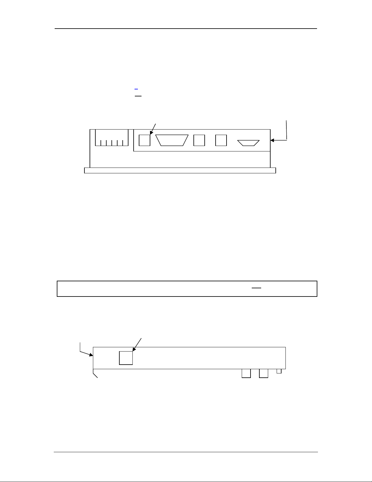
2.1 Built-In Ethernet Module
As shown in Table 1.1 (page
in to the OCS unit, requiring no
the RJ-45 Ethernet connector on OCS451, OCS551 and OCS651 units.
Figure 2-1 – SVGA Color Graphics OCS Bottom View
7), for some OCS Models, the SmartStack Ethernet Module is built-
user-installation. For example, Figure 2.1 shows the location of
Ethernet Connector (OCS551 and OCS651) Ethernet Connector
(OCS451)
2.2 User-Installed Ethernet Module
For other OCS or RCS Models, the SmartStack Ethernet Module must be user-installed on the
back of the OCS / RCS unit. Figure 2.2 shows the locations of the Ethernet RJ-45 connector and
LED indicators on the user-installed SmartStack Ethernet Module.
Note: Normally, a user-installed Ethernet Module occupies the first I/O slot on the back of the
OCS or RCS unit. The only exception to this rule occurs if a FOX100 Module is also
installed. In this case, the FOX100 Module occupies the first I/O slot, and the Ethernet
Module is installed into the second I/O slot.
Caution: For proper functioning and to avoid possible damage, do not install more than
For more details on installing SmartStack I/O modules, refer to Chapter 2 of the Control Station
Hardware Manual (MAN0227), which also provides a handy checklist concerning panel box
layout and minimum clearance requirements.
Link & Activity LEDs Ethernet Connector
four SmartStack Modules on the back of an OCS or RCS controller.
Figure 2-2– User-Installed Ethernet Module Side View
11/30/2009 Page 11 of 98 # 958
Page 12

CH.2 SUP0740-07
2.3 Network Administrator Installation Notes
When connecting an Ethernet Module to a local network, the following information is provided to
the Network Administrator, as an aid in configuring Ethernet Hubs, Routers, Switches, Gateways
and Servers.
2.3.1 UDP and TCP Ports
Each protocol supported by the Ethernet Module (except ICMP) uses one or more UDP and/or
TCP Ports as the destination port for all messaging, as shown in Table 2.1. (Note: Any port can
be used as the source port.) Required port usage for the supported proto col s should be taken into
account when configuring Ethernet Routers and Gateways.
Table 2.1 – Ethernet Protocol UDP and TCP Port Usage
Ethernet Protocol
Hexadecimal Decimal Hexadecimal Decimal
UDP Port TCP Port
EGD 4746 18246
SRTP 4745 18245
Modbus 01F6 502
CsCAN 4845 18501
Ethernet / IP 08AE 2222 AF12 44818
FTP 0014 and 0015 20 and 21
HTTP 0050 80
* SMTP 0035 53 0019 25
Note: * SMTP connects via TCP connection using default port 25 (user configurable), but in
Cscape | Messaging | Email feature if user selects 'Obtain SMTP Server IP Address
from DNS Server' then UDP connection will be used to obtain Server IP, in such case UDP
port 53(Decimal) will be used.
2.3.2 EGD Unicast and Multicast IP Addressing
When using Ethernet Global Data (EGD) protocol for peer-to-peer communication, there are two
methods for sending data: (1) send to a single device or (2) send to a group of devices.
When sending to a single device (method 1), EGD protocol uses Unicast IP Addressing. This
means that the IP header’s 32-bit Destination IP Address will contain the intended recipient’s
unique IP Address.
When sending to a group of devices (method 2), EGD protocol uses Multicast IP Addressing.
This means that the IP header’s 32-bit Destination IP Address will contain one of the 32 Multicast
IP Addresses shown in Table 2.2.
Table 2.2 – EGD Multicast IP Addressing
Group ID Multicast IP Address
1 224.0.7.1
2 224.0.7.2
:
:
:
:
32 224.0.7.32
11/30/2009 Page 12 of 98 # 958
Page 13

SUP0740-07 CH.2
Ethernet Switches normally don’t support Multicast IP Addressing, while Ethernet Hubs do
support Multicast IP Addressing. Some Ethernet Routers, known as Multicast Routers, do
support
Multicast IP Addressing, by using Internet Group Management Protocol (IGMP).
Note: For those customers wanting to use Multicast Routers to connect EGD devices, the
Ethernet Module automatically handles IGMP communication with Multicast Routers.
For more information regarding EGD protocol, refer to Chapter 6 of this manual.
2.3.3 Internet Connectivity
Since the Ethernet Module uses a standard TCP/IP protocol stack (powered by NetX and
ThreadX), it can communicate beyond the local network, and on the Internet, for all protocols
EGD. To do so, the Ethernet Module must be configured with the IP Address of a Network
except
Gateway server, which allows communication outside the local network. See Default Gateway
configuration under step 5 of Section 3.1 (page
18) in this manual for details.
Note: As network complexity increases, due to Ethernet Hubs, Routers, Switches, Gateways,
and the Internet, the worst-case network delay increases. In many cases, the client
software must be configured to account for this time lag. For example, Cscape’s Timeout
can be adjusted as shown under step 2 of Section 4.2 (page
24) in this manual.
2.3.4 IMPORTANT: Wireless Network Considerations
When using wireless equipment with industrial networks, make sure the system is designed and
installed by personnel that have been trained to use wireless networks in industrial environments.
Site surveys, selection of equipment and installation can be critical in network performance.
In general the 802.11b- based equipment is not
a good choice in industrial environments. The
frequencies and modulation techniques used in the “b” standard are very susceptible to multipath interference in industrial environments (large metal objects, dense walls and floors, etc.)
The 802.11a and 802.11g are less susceptible to this interference.
Using UDP based protocols such as Ethernet Global Data (EGD) must be carefully considered
when using wireless networks. Wireless networks are more likely to lose or damage
communication packets. Many UDP based protocols, including EGD, do not
detect and retransmit
lost or damaged packets and depend on periodic data transmissions to compensate for this lost
data. If your system requires a UDP protocol with a wireless network, make sure it is designed
such that random periods without refreshed data do not
adversely affect the operation of your
system.
Depending on the architecture of the wireless network and the protocols used, wireless networks
often produce collisions and extra data packets that are not
experienced when using a traditional
wire and switch-based network. The extra collisions and traffic coupled with the typically lower
bandwidth and higher latency of wireless networks can cause degradation in performance.
11/30/2009 Page 13 of 98 # 958
Page 14

CH.2 SUP0740-07
2.4 Safety
When found on the product, the following symbols specify:
Warning: Consult user documentation.
Warning: Electrical Shock Hazard.
WARNING: Remove power from the OCS controller, CAN port, and any peripheral equipment
connected to this local system before adding or replacing this or any module.
WARNING: To avoid the risk of electric shock or burns, always connect the safety (or earth)
ground before making any other connections.
WARNING: To reduce the risk of fire, electrical shock, or physical injury it is strongly
recommended to fuse the voltage measurement inputs. Be sure to locate fuses as close to the
source as possible.
WARNING: Replace fuse with the same type and rating to pro vide protection against risk of
fire and shock hazards.
WARNING: In the event of repeated failure, do not
indicates a defective condition that will not
WARNING: Only qualified electrical personnel familiar with the construction and operation of
this equipment and the hazards involved should install, adjust, operate, or service this
equipment. Read and understand this manual and other applicable manuals in their entirety
before proceeding. Failure to observe this precaution could result in severe bodily injury or
loss of life.
clear by replacing the fuse.
replace the fuse again as a repeated failure
For detailed installation and a handy checklist
that covers panel box layout requirements and
minimum clearances, refer to the hardware manual of the controller you are using. (See the
Additional References section in this document.)
• All applicable codes and standards need to be followed in the installation of this product.
• For I/O wiring (discrete), use the following wire type or equivalent: Belden 8917, 16 AWG
or larger.
Adhere to the following safety precautions whenever any type of connection is made to the
module.
• Connect the green safety (earth) ground first before making any other connections.
• When connecting to electric circuits or pulse-initiating equipment, open their related
breakers. Do not
make connections to live power lines.
• Make connections to the module first; then connect to the circuit to be monitored.
• Route power wires in a safe manner in accordance with good practice and local codes.
• Wear proper personal protective equipment including safety glasses and insulated gloves
when making connections to power circuits.
• Ensure hands, shoes, and floors are dry before making any connection to a power line.
• Make sure the unit is turned OFF before making connection to terminals. Make sure all
circuits are de-energized before making connections.
• Before each use, inspect all cables for breaks or cracks in the insulation. Replace
immediately if defective.
11/30/2009 Page 14 of 98 # 958
Page 15
SUP0740-07 CH.3
CHAPTER 3: GENERAL CONFIGURATION
Note: The following configuration is required for all applications regardless of the protocols used.
Additional configuration procedures must be performed for each protocol used as described in the
configuration sections of the next several chapters.
3.1 Ethernet Module Configuration
To configure the Ethernet Module, use Cscape Programming Software to perform the following
six steps:
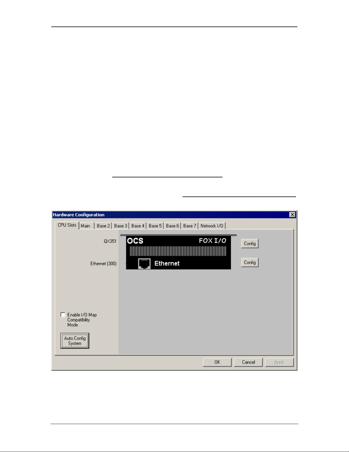
1. On the main Cscape screen, select the Controller menu and its I/O Configure sub-menu to
open the I/O Configuration dialog (Figure 3.1 or Figure 3.2).
2. If configuring a different OCS Model than the one shown in the I/O Configuration dialog, click
on the topmost Config button, select the desired OCS Model, and then click OK.
Note: Figure 3.1 shows a typical I/O Configuration dialog for OCS Models, which have Ethernet
Modules built-in. For these models, step 3 should be skipped
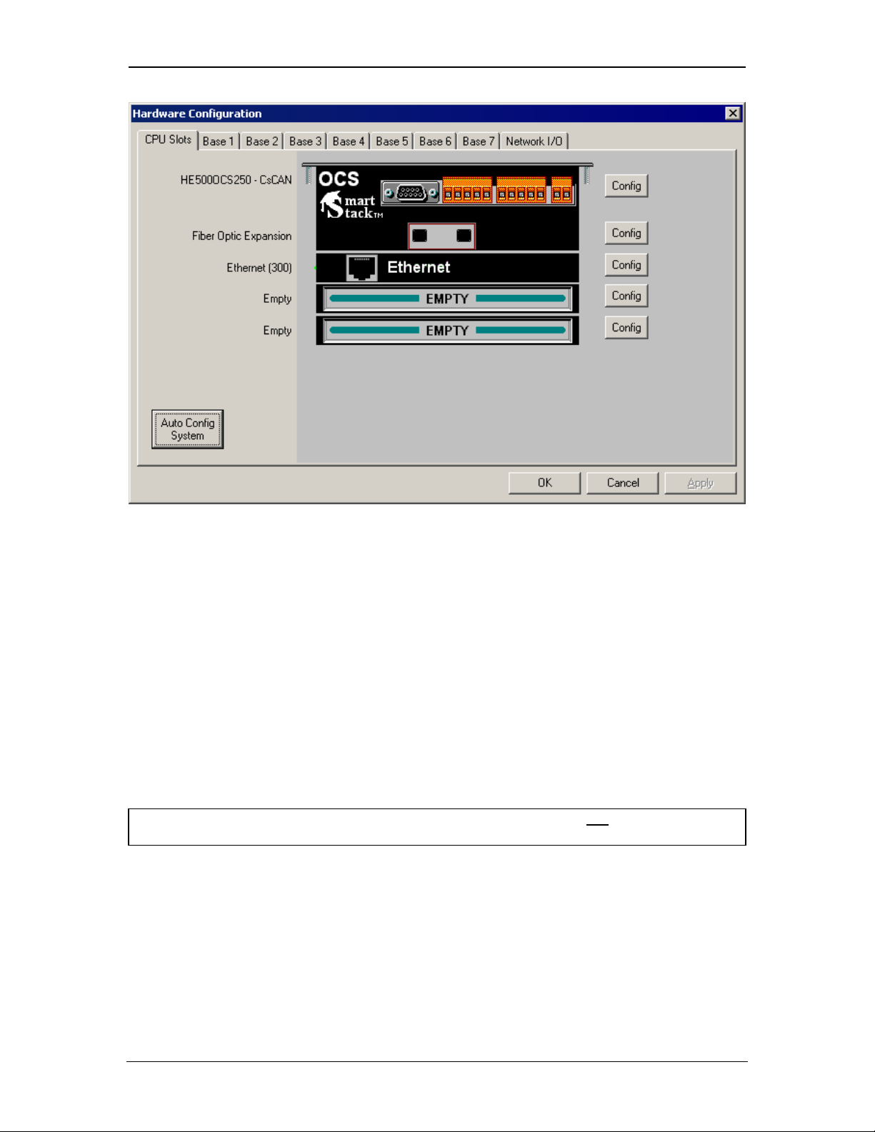
Figure 3.2 shows a typical I/O Configuration dialog for other OCS Models, in which the
Ethernet Module is a user-installable option. For these models, step 3 must be performed
to configure the Ethernet Module into a SmartStack I/O slot.
.
,
Figure 3-1 – Hardware Configuration Dialog – OCS Models With Built-In Ethernet
11/30/2009 Page 15 of 98 # 958
Page 16
CH.3 SUP0740-07
Figure 3-2– Hardware Configuration Dialog – OCS Models With User-Installable Ethernet
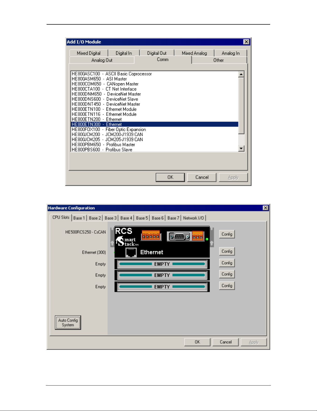
3. To configure a user-installable Ethernet Module into a SmartStack I/O slot, do the following:
a. Referring to Figure 3.2 above, click on the Config button to the right of the desired I/O
slot, which will open the Add I/O Module dialog, as shown in Figure 3.3.
b. Click the Comm tab and select the desired HE800ETNxxx item from the list.
c. Click OK. The Ethernet Module is now configured into an I/O slot, as shown in Figure 3.4.
Note: Normally, a user-installed Ethernet Module occupies the first I/O slot on the back of the
OCS or RCS unit. The only exception to this rule occurs if a FOX100 Module is also
installed. In this case, the FOX100 Module occupies the first I/O slot, and the Ethernet
Module is installed into the second I/O slot.
Caution: For proper functioning and to avoid possible damage, do not install more than
four SmartStack Modules on the back of an OCS or RCS controller.
11/30/2009 Page 16 of 98 # 958
Page 17
SUP0740-07 CH.3
Figure 3.3– Add I/O Module Dialog – Comm Tab and Ethernet Module Selected
Figure 3.4– Hardware Configuration Dialog – User-Installed Ethernet Module
11/30/2009 Page 17 of 98 # 958
Page 18
CH.3 SUP0740-07
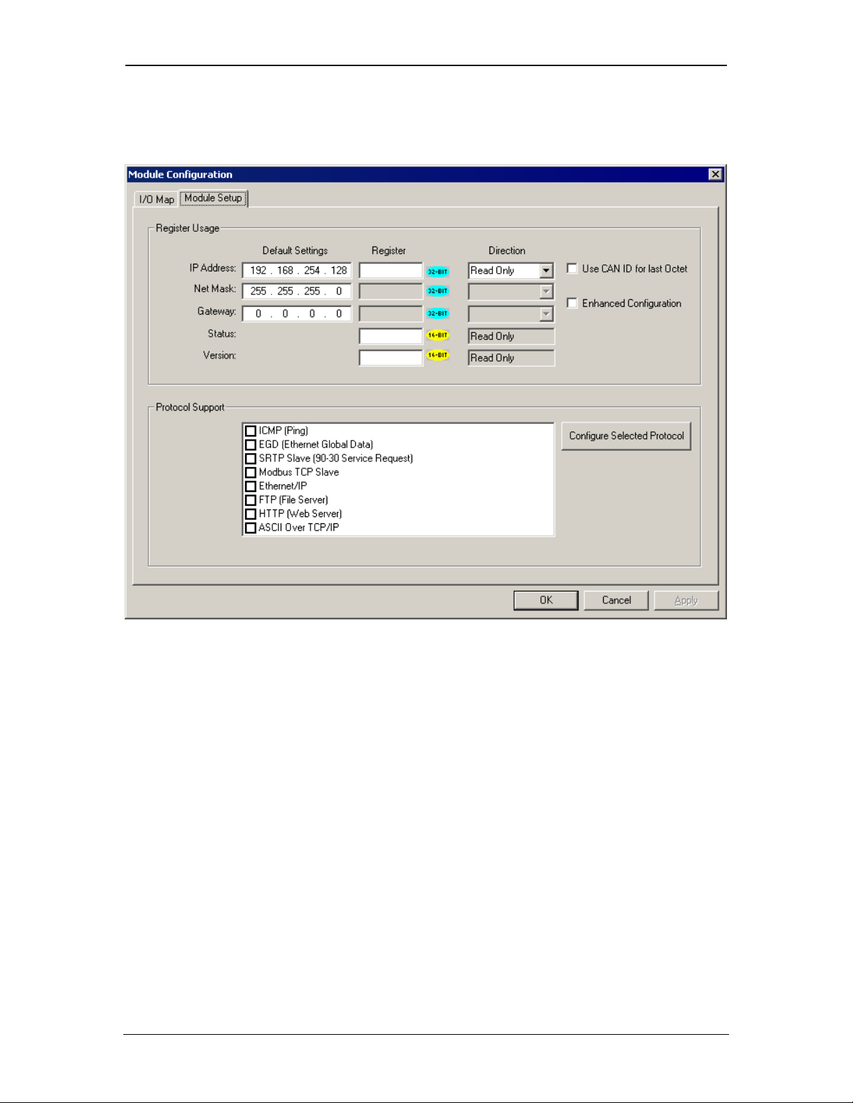
4. Now it is time to configure the Ethernet Module as appropriate for the application. Referring to
Figure 3.1 or 3.4 above, click the Config button to the right of the Ethernet Module, and then
select the Module Setup tab, revealing the Ethernet Module Configuration dialog (Figure 3.5).
Figure 3.5– Ethernet Module Configuration Dialog - Module Setup Tab Selected
5. Configure the Ethernet Module parameters as follows:
It has two parts 1. Register Usage and 2. Protocol Support
Register Usage:
i. IP Address: Enter the static IP Address for the Ethernet Module being configured.
Note: IP Addresses are entered as four numbers, each ranging from 0 to 255. These
four numbers are called octets and they are always separated by decimal points.
ii. Net Mask: Enter the Net Mask (sometimes called Subnet Mask) being used by all
nodes on the local network. Typical local networks use Class C IP Addresses, in
which case the low octet (rightmost number) is used to uniquely identify each node
on the local network. In this case, the default Net Mask value of 255.255.255.0
should be used.
iii. Gateway: Enter the IP Address of a Gateway Server on the local network that allows
for communication outside of the local network. To prevent the Ethernet Module from
communicating outside the local network, set the Default Gateway IP Address to
0.0.0.0 (the default setting).
11/30/2009 Page 18 of 98 # 958
Page 19
SUP0740-07 CH.3
iv. Status Register: Enter an OCS Register reference (such as %R100) to indicate
which 16-bit OCS register will have the Ethernet Status word written to it. Table 3.1
shows how this register value is formatted and explains the meaning of each bit in
the Status Word.
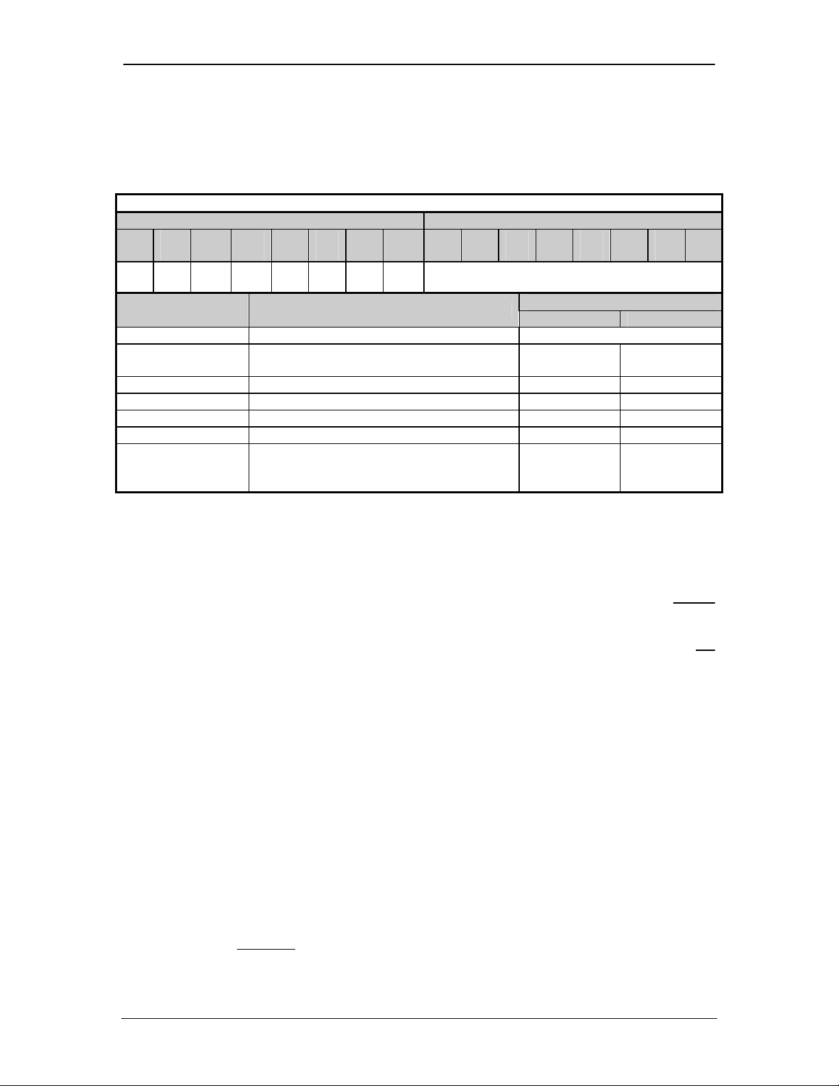
Table 3.1 - Ethernet Status Word Register Format
High Byte Low Byte
Bit
Bit
Bit
Bit
Bit
Bit
Bit
Bit 9 Bit 8 Bit 7 Bit 6 Bit 5 Bit 4 Bit 3 Bit 2 Bit
16
15
14
13
12
11
10
1
0 0 Dup Spd 0 Rx Tx Link TCP Connections
Status Bit(s) Status Indication
Status Values
Minimum Maximum
0 Reserved Always 0
Dup Link Duplex (Auto-Negotiated)
0 = Half
Duplex
1 = Full
Duplex
Spd Link Speed (Auto-Negotiated) 0 = 10 Mbps 1 = 100 Mbps
Rx Receive State 0 = Inactive 1 = Active
Tx Transmit State 0 = Inactive 1 = Active
Link Link State 0 = Down 1 = Up
Total Number of Active TCP Connections
TCP Connections
(CsCAN, SRTP, Modbus, EIP, FTP,
0 40
HTTP)
v. Version Register: Enter an OCS Register reference (such as %R101) to indicate
which 16-bit OCS register will have the Ethernet Firmware Version written to it. The
value stored in the Version Register is: (Ethernet Firmware Version * 100). For
example, for Ethernet Firmware Version 4.30, the Version register will contain 430.
For the Status and Version registers (if configured), the Direction settings are always
Read Only
vi. Use CAN ID for last Octet: The Use CAN ID for last Octet checkbox does not
affect Net Mask, Gateway, Status or Version configuration. If the checkbox is
checked then it behaves as follows:
A. If the IP Address Direction combo box is Read / Write, the Use CAN ID for last
Octet checkbox will be unchecked and grayed.
B. If the IP Address Direction combo box is empty or Read Only, the Use CAN ID
for last Octet checkbox will be ungrayed, and can then be unchecked or
checked.
C. If the Use CAN ID for last Octet checkbox is checked, the unit’s 8-bit CAN
Network ID replaces the last (rightmost) octet of the Default IP Address, and the
combined result will be the unit’s IP Address. In this case, if the IP Address
Register edit box contains a valid OCS register, the indicated register will be
loaded with the combined IP Address.
vii. Enhanced Configuration
To perform Enhanced Configuration, first check the Enhanced Configuration
checkbox. In this case, IP Address, Net Mask, Gateway, Status and Version can
all be optionally
assigned to OCS registers. By default, the register edit boxes are
empty indicating that no registers are assigned.
11/30/2009 Page 19 of 98 # 958
Page 20

CH.3 SUP0740-07
As with the IP Address register (described in the Standard Configuration section
below), Net Mask and Gateway register Directions can be set to Read Only or Read
/ Write
With Cscape 8.2 onwards, the ETN Module Configuration dialog has been enhanced
to support the following:
1. More easily expanded Protocol Support list for current and future
protocols.
2. Optional Enhanced Configuration:
a. Allows Net Mask and Gateway to be optionally read from or written
to OCS registers.
b. Allows all
OCS register assignments to be optional instead of
mandatory.
Ethernet Module Configuration Dialog Rules
The following rules describe how the new Ethernet Module Configuration Dialog is to
be used:
I. The Enhanced Configuration checkbox will be unchecked and grayed if
configuring an ETN100 or ETN116 Module.
II. If the Enhanced Configuration checkbox is checked, Cscape will display an
error message and will abort an I/O Configuration download if:
A. Configuring an ETN200 or ETN300 Module with ETN Firmware < 4.35,
B. Configuring an OCS, QX or NX with Engine Firmware < 11.91.
III. If the Enhanced Configuration checkbox is unchecked, the dialog maintains
backward compatibility as follows:
A. The Net Mask and Gateway Register edit boxes will be empty and
grayed.
B. The Net Mask and Gateway Direction combo boxes will be empty and
grayed.
C. All other dialog objects function the same as in the Cscape 8.0b dialog,
except as follows:
1. The new IP Address Direction combo box replaces the old Get IP
from IP Addr Register checkbox. A Direction of Read Only, is
equivalent to unchecked and a Direction of Read / Write is equivalent
to checked.
2. The new Protocol Support area contains a protocol list box showing
the protocols supported by the platform being configured. Each
protocol in the list box has a checkbox in front of it that can be checked
to enable the protocol. The single Config Selected Protocol button
applies to the protocol that is currently highlighted in the list box.
Standard Configuration
To perform Standard Configuration, simply leave the Enhanced Configuration
checkbox unchecked.
In this case, Net Mask and Gateway cannot
Address, Status and Version must
be assigned to OCS registers.
be assigned to OCS registers, while IP
11/30/2009 Page 20 of 98 # 958
Page 21

SUP0740-07 CH.3
Note that the assigned IP Address register’s Direction can set to Read only or Read
/ Write.
If the register is Read only, the Default IP Address becomes the unit’s IP Address and
is loaded into the assigned register, where it can be read by the application. (Note: In
this case, the low octet of the IP Address can be replaced with the unit’s CAN Network
ID, by checking the Use CAN ID for last Octet checkbox.)
If the register is Read / Write, the application should write an IP Address to the
assigned register, and this value will then be the unit’s IP Address. (In this case, the
Default IP Address is used only if communication is lost during an I/O configuration
download; otherwise the Default IP Address is ignored.)
Protocol Support:
The Protocol Support area contains a list of all the protocols supported by the platform being
configured. To activate a protocol, check its checkbox.
For protocols that require additional configuration, click on a listed protocol to select it and then
click the Configure Selected Protocol button. This will open a new dialog with configuration
options for the selected protocol (Detailed configuration of the protocols is explained in the
corresponding chapters below).
6. Click OK to accept the new Ethernet Module configuration.
3.2 Ethernet Module IP Address
The Ethernet Module obtains its IP Address in one of three different ways, depending on how the
Use CAN ID for last Octet, Enhanced Configuration & IP Address direction checkboxes
(Figure 3.5) are configured, as described in the following three se ctions.
3.2.1 Static IP Address
Use CAN ID for last Octet
IP Address Direction (Read Only)
In this mode, the Ethernet Module’s IP Address comes from the IP Address parameter only, and
does not
use the CAN Network ID for the low octet and does not use IP Address Register to
obtain an IP Address from an OCS register. In this case the Ethernet Module writes the static IP
Address to the 32-bit OCS register indicated by the IP Address Register parameter.
3.2.2 Static IP Address with CAN ID
9 Use CAN ID for last Octet
IP Address Direction (Read Only)
In this mode, the Ethernet Module’s IP Address comes from a combination of the IP Address
parameter and the OCS/RCS CAN Network ID. The most significant (leftmost) three octets of the
IP Address come from the IP Address parameter. The least significant (rightmost) octet of the IP
Address is taken from the OCS (or RCS) CAN Network ID. In this case the Ethernet Module
writes the adjusted IP Address to the 32-bit OCS register indicated by the IP Address Register
parameter.
11/30/2009 Page 21 of 98 # 958
Page 22

CH.3 SUP0740-07
3.2.3 IP Address from OCS Register
Use CAN ID for last Octet
9 IP Address Direction (Read / Write)
In this mode, the Ethernet Module’s IP Address comes from an OCS register. The IP Address
Register parameter indicates which 32-bit OCS registers to read the IP Address from. The static
IP Address parameter is not
used in this situation, except to set the Default IP Address in non-
volatile memory.
Note: Every time an I/O configuration is successfully downloaded to an OCS with an Ethernet
Module, the static IP Address, Net Mask and Default Gateway parameters are stored in
non-volatile memory. In the event of a future unsuccessful I/O configuration download, the
Ethernet Module will communicate using these 3 stored parameters. This is done in an
effort to minimize potential loss of communication, which would require direct on-site
intervention to correct.
11/30/2009 Page 22 of 98 # 958
Page 23
SUP0740-07 CH.4
CHAPTER 4: CSCAN OVER ETHERNET PROTOCOL
4.1 CsCAN over Ethernet Overview
This chapter describes CsCAN TCP Server Communication protocol, also known as CsCAN over
Ethernet protocol.
CsCAN over Ethernet protocol allows a CsCAN Host Programming Tool, such as Cscape, to
access an OCS unit, as though it were connected directly to the OCS programming serial port.
4.2 CsCAN over Ethernet Configuration
The Ethernet Module requires no
protocol. Only the general Ethernet Module Configuration previously described in Chapter 3 is
required. As long as the Ethernet Module has been assigned an IP Address and Net Mask, it will
automatically respond to CsCAN over Ethernet messages sent to it by a PC running Cscape.
To connect Cscape to an OCS unit’s Ethernet Module, using CsCAN over Ethernet protocol,
perform the following two steps:
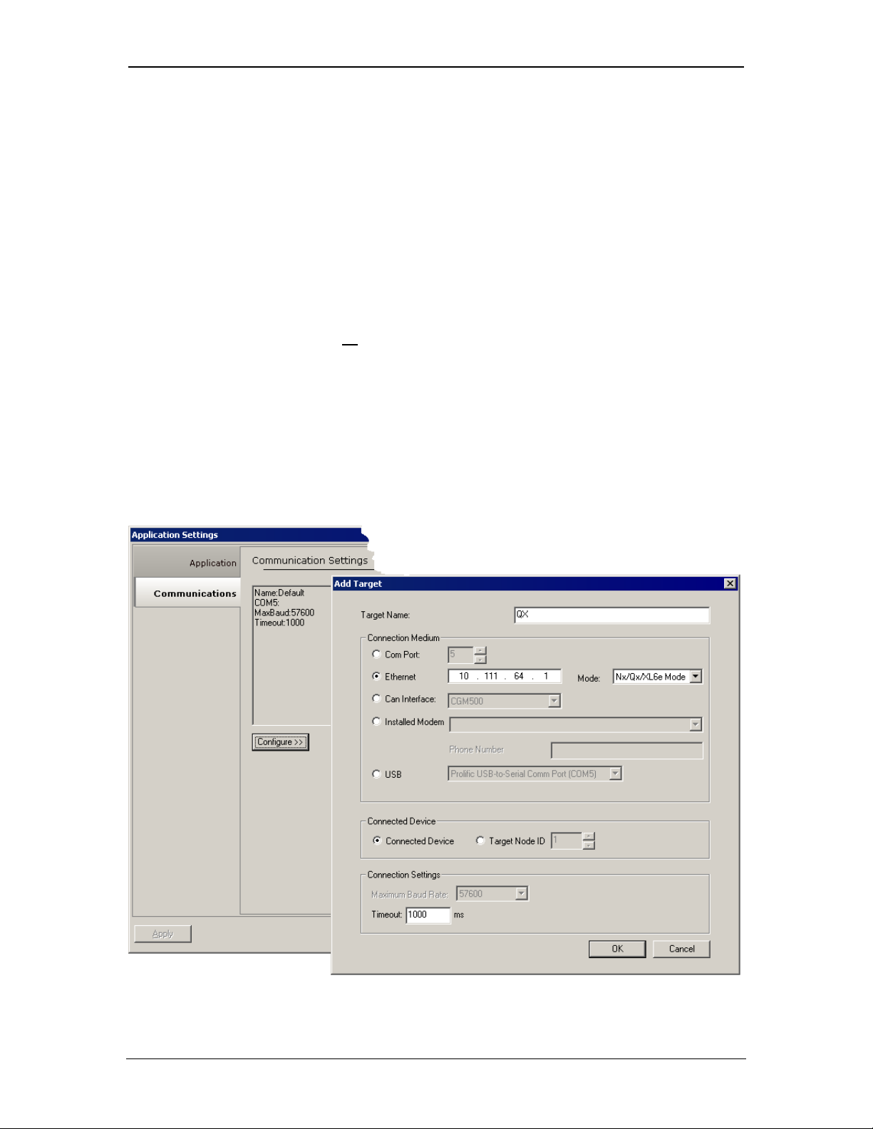
1. On the main Cscape screen, select the Tools menu > Application Settings >
Communications and then click on Configure button to display Add Target dialog
(Figure 6.1).
protocol-specific configuration for CsCAN over Ethernet
Figure 4.1– Program Options Dialog – Communications Port Tab and Ethernet Selected
11/30/2009 Page 23 of 98 # 958
Page 24

CH.4 SUP0740-07
2. Select the Ethernet from the Connection Medium list, and then set the Target IP Address
and Timeout parameters as follows:
Target IP Address: Enter the IP Address previously assigned to the target Ethernet Module.
Please refer to Chapter 3 regarding how to assign an IP Address to an Ethernet Module.
Timeout: Enter a number between 1000 and 65,000 (in milliseconds) for the maximum expected
network round-trip communication time. This value determines how long Cscape will wait for a
response after it sends a CsCAN over Ethernet protocol command to the Ethernet Module.
Note: For most local network applications, the default Timeout value of 1000 is sufficient.
However, there are some network considerations, which may require the Timeout
value to be increased to facilitate reliable communication. This includes heavily loaded
networks, complex networks with multiple levels of routers and switches, and Internet
communication.
Also, because CsCAN communication is affected by ladder code scan rate, the
Timeout value may have to be further increased to compensate for applications with
very slow scan rates.
4.3 CsCAN over Ethernet Operation
As stated previously, the Ethernet Module allows a CsCAN Host Programming Tool, such as
Cscape, to use CsCAN over Ethernet to perform all standard supervisory control, monitoring and
programming functions with the OCS, as though it were connected directly to the OCS
programming serial port.
These standard supervisory functions include the Ethernet Module’s ability to handle passthrough communication with the CsCAN Nodes attached to the OCS CAN port. This feature is
known as CsCAN single-point programming. For example, referring back to Figure 1.1 (page
Figure 1.1– Example of an Ethernet Network) the PC (running Cscape) can use OCS #1’s
ETN200 Module as a gateway, to easily access all of the CsCAN Nodes on OCS #1’s CsCAN
network.
4.4 CsCAN over Ethernet Downloading Precautions
When downloading a new Ethernet configuration to a target OCS, using CsCAN over Ethernet
protocol, extra care should be taken.
In particular, when downloading I/O and Network Configuration, the Ethernet Module
configuration is also downloaded, which has the potential to change the target device’s IP
Address, or it could even remove the Ethernet Module configuration entirely, resulting in loss of
communication and a failed download.
For this reason, when the Cscape user modifies the I/O Configuration, and then starts to
download it using CsCAN over Ethernet, Cscape issues a warning message, as shown in Figure
4.2.
11/30/2009 Page 24 of 98 # 958
Page 25

SUP0740-07 CH.4
Figure 4.2 – I/O Configuration Download Warning
4.4.1 How to Prevent Losing Communication
using CsCAN over Ethernet to download a new I/O Configuration, to an OCS with an
Before
Ethernet Module installed, the application programmer should:
1. Make sure the new I/O Configuration contains an Ethernet Module configuration.
2. Make sure the new Ethernet configuration will not
change the IP Address.
Refer to Chapter 3 on how to check and/or correct Ethernet Module configuration and pay
particular attention to step 5 of the Ethernet Module configuration process in Section 3.1 (page
18), and to Section 3.2 (page 21), which explains in detail how the Ethernet Module obtains an IP
Address.
If the new Ethernet configuration specifies Static IP Address (Section 3.2.1 [page
the IP Address parameter (Figure 3.5 [page
18]) matches Cscape’s Target IP Address (Figure
21]), make sure
4.1).
If the new Ethernet configuration specifies Static IP Address with CAN ID (Section 3.2.2 [page
21]), make sure the IP Address, which will be built from the combination of the IP Address
parameter (Figure 3.5 [page
18]) and the OCS/RCS CAN Network ID, matches Cscape’s Target
IP Address (Figure 4.1).
If the new Ethernet configuration specifies IP Address from OCS Register (Section 3.2.3 [page
22]), make sure the OCS register indicated by the IP Addr Register parameter (Figure 3.5 [page
18]) contains an IP Address, and that it matches Cscape’s Target IP Address (Figure 4.1). If
necessary, use Cscape’s Data Watch facility to set the OCS register to the correct IP Address
before downloading.
4.4.2 How to Recover from Lost Communication
If the Ethernet Module’s IP Address changes as a result of using CsCAN over Ethernet to
download a new user program, activity will halt at the end of the I/O Configuration download, and
communication between Cscape and the target OCS will
be lost. Then, after several seconds,
Cscape will display a Communication Timeout error.
If this happens, it is possible to recover Cscape communication with the target OCS, as follows:
1. Referring to Chapter 3 (especially Section 3.2 [page
21]) and to Section 4.4.1, determine
the Ethernet Module’s new IP Address, by using Cscape to re-examine the I/O
Configuration just downloaded.
2. Referring to Figure 4.1, change Cscape’s Target IP Address to match the Ethernet
Module’s new IP Address.
3. Try performing the download again.
11/30/2009 Page 25 of 98 # 958
Page 26
CH.4 SUP0740-07
4. If this does not succeed, try changing Cscape’s Target IP Address (Figure 4.1) to match
the static IP Address parameter (even if it is grayed out).
5. If all else fails, connect a PC running Cscape directly to the target OCS unit’s
programming serial port, repeat the download, and then use Data Watch to examine the
register indicated by the IP Addr Register parameter (Figure 3.5 [page
the Ethernet Module’s new IP Address.
Note: If the application programmer wants to use CsCAN over Ethernet to intentionally change
an Ethernet Module’s IP Address, do this by (1) starting the download, (2) waiting for
Cscape to timeout and (3) performing steps 1, 2 and 3 of the recovery process, as
described above.
4.5 CsCAN over Ethernet Security
To prevent the use of CsCAN over Ethernet protocol to gain unauthorized access to an OCS or
RCS, Cscape Programming Software and OCS Ethernet Firmware have the ability to passwordprotect CsCAN over Ethernet communication. To implement CsCAN over Ethernet Security, use
Cscape Programming Software, to perform the following nine steps:
1. Open the user program previously created for the target OCS or RCS controller.
18]), to discover
2. IF THE USER PROGRAM HAS ALREADY BEEN SET UP WITH SECURITY
PASSWORDS, FIRST LOG-IN AS THE ADMINISTRATOR. TO DO THIS, SELECT THE
TOOLS MENU AND ITS SECURITY SUB-MENU, CLICK LOG-IN, ENTER THE
ADMINISTRATOR PASSWORD, AND THEN CLICK OK. CSCAPE WILL THEN
ACKNOWLEDGE THE ADMINISTRATOR LOG-IN; CLICK OK AGAIN
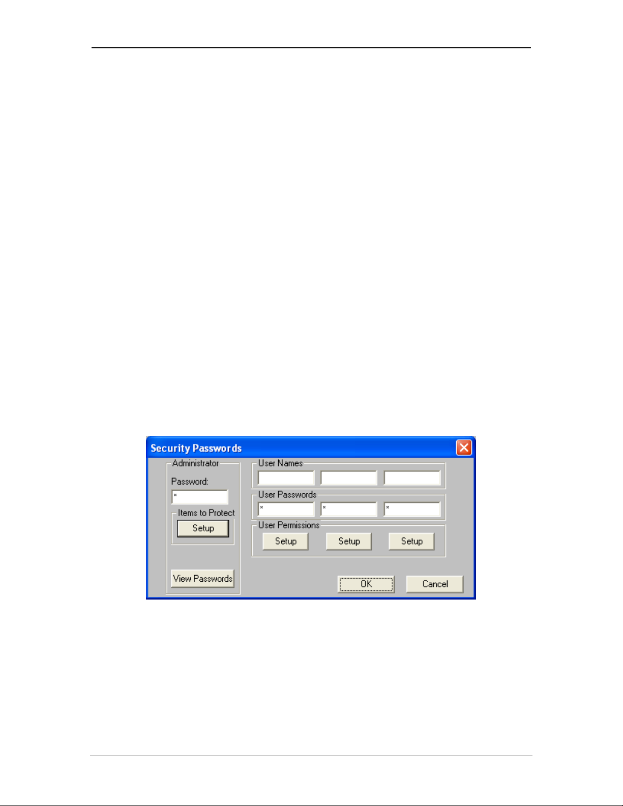
3. On the main Cscape screen, select the Tools menu and its Security sub-menu, and then
click Change Passwords, to open the Security Passwords dialog, as shown in Figure 4.3.
.
Figure 4.3 – Security Passwords Dialog
4. Click on the View Passwords button to view the Administrator and User passwords.
5. Change passwords and user names as desired for the application. Note that passwords are
numeric values between 1 and 999,999, while the user names can be any text from 1 to 15
characters long.
11/30/2009 Page 26 of 98 # 958
Page 27
SUP0740-07 CH.4
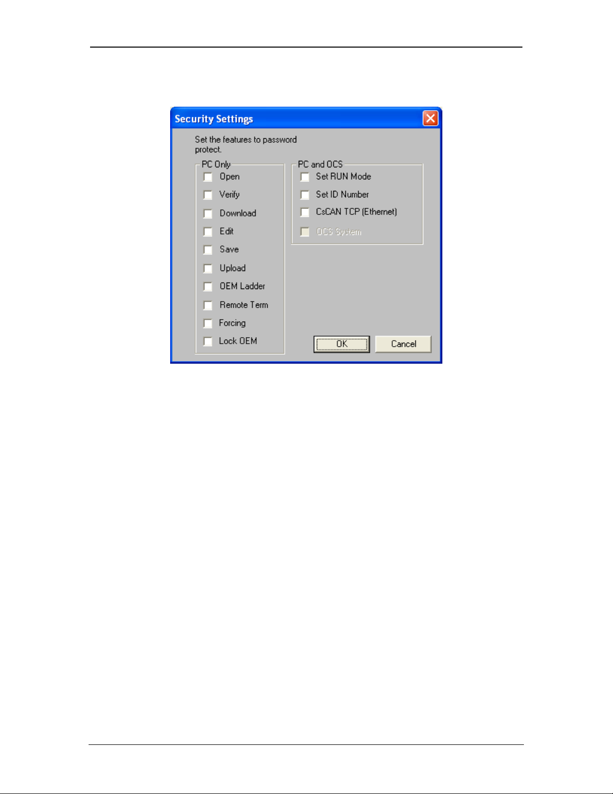
6. Click on the Items to Protect Setup button to open the Administrator’s Security Settings
dialog, as shown in Figure 4.4.
Figure 4.4– Administrator’s Security Settings Dialog
7. To password-protect CsCAN over Ethernet protocol, make sure the CsCAN TCP (Ethernet)
checkbox is checked in the Administrator’s Security Settings dialog, as shown in Figure 4.4.
Then click OK.
8. The Administrator password is always authorized for all protected features. If desired, one or
more of the user passwords can also be authorized for CsCAN over Ethernet communication.
To do this, refer to Figure 4.3 and click one of the User Permissions Setup buttons to open
that user’s Security Settings dialog, which will be similar to Figure 4.4. Then check the
CsCAN TCP (Ethernet) checkbox and click OK.
9. After downloading the user program to the target OCS or RCS, both Cscape and the OCS (or
RCS) controller will enforce the new password security for CsCAN over Ethernet protocol.
11/30/2009 Page 27 of 98 # 958
Page 28

CH.4 SUP0740-07
NOTES
11/30/2009 Page 28 of 98 # 958
Page 29
SUP0740-07 CH.5
CHAPTER 5: INTERNET CONTROL MESSAGE PROTOCOL (ICMP)
5.1 ICMP Overview
ICMP is used for diagnostic purposes only, to determine if another device exists on the Ethernet
network.
Using ICMP, the Ethernet Module sends Ping Echo Requests to another device, and expects the
other device to answer with Ping Echo Responses. The Ethernet Module measures the round-trip
time of each Ping Echo Request / Response exchange and puts the result (in milliseconds) into
an OCS register.
In addition, when the Ethernet Module receives a Ping Echo Request from another device, it
answers with a Ping Echo Response.
Note: Although ICMP supports other network diagnostics, the Ethernet Module only supports
Ping.
5.2 ICMP Configuration
If ICMP protocol will be used in the application, ICMP Configuration must be performed, in
addition to the general Ethernet Module Configuration previously described in Chapter 3. To
configure ICMP protocol, use Cscape Programming Software to perform the following five steps:
1. Open the Ethernet Module Configuration dialog (Figure 3.5 [page
Chapter 3.
2. Enable ICMP by checking the ICMP (Ping) checkbox in the Module Configuration dialog
(Figure 3.5).
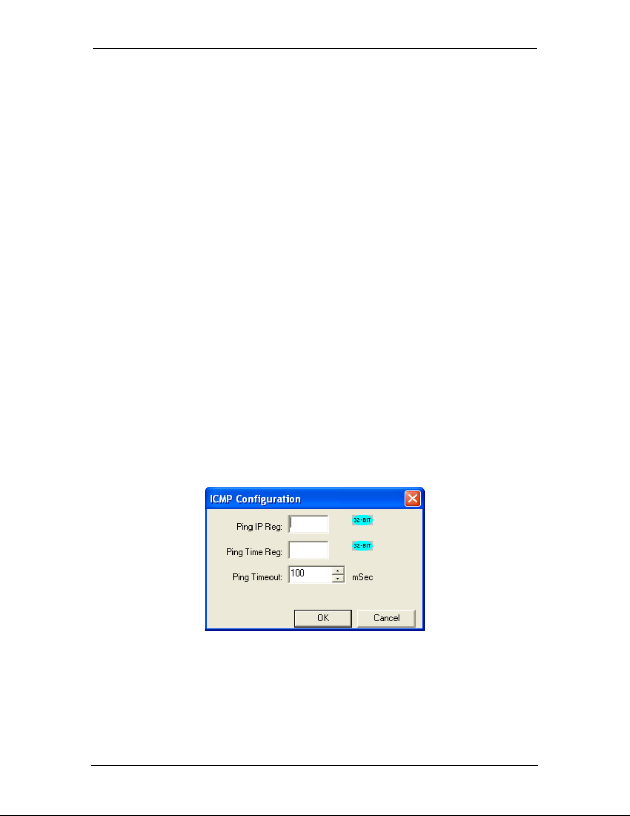
3. Click on the Config button next to the ICMP (Pin g) checkbox to open the ICMP Configuration
dialog (Figure 5.1).
18]), as described in
Figure 5.1– ICMP Configuration Dialog
4. Set up the ICMP Configuration parameters as follows:
Ping IP Reg: Enter an OCS Register reference (such as %R200) to indicate which 32-bit
OCS register will be read to obtain the IP Address of the network device to send Ping Echo
Requests to.
11/30/2009 Page 29 of 98 # 958
Page 30

CH.5 SUP0740-07
Ping Time Reg: Enter an OCS Register reference (such as %R202) to indicate which 32-bit
OCS register will be written with the Ping Echo Request / Response round-trip time (in
milliseconds).
Ping Timeout: Enter a number between 100 and 100,000 for how often (in milliseconds) the
Ethernet Module should send Ping Echo Requests.
5. Click OK to accept the new ICMP Configuration.
5.3 ICMP Operation
To start Ping Echo Requests, use Ladder Code, User Screens or Cscape Data Watch to write an
IP Address to the OCS register indicated by Ping IP Reg. To check the resulting Ping Echo
Response times, read the OCS register indicated by Ping Time Reg. If the round-trip time
exceeds the configured Ping Timeout (or if there is no response at all), the reported response
time will be -1.
To stop Ping Echo Requests, write 0.0.0.0 to the OCS register indicated by Ping IP Reg.
Note that ICMP protocol is active even when the OCS is not
OCS is not
in RUN mode, User Screens and Cscape Data Watch can still be used to control and
in RUN mode. Therefore, when the
monitor ICMP Pinging.
11/30/2009 Page 30 of 98 # 958
Page 31

SUP0740-07 CH.6
CHAPTER 6: ETHERNET GLOBAL DATA PROTOCOL (EGD)
6.1 EGD Overview
Ethernet Global Data (EGD) protocol is a GE Fanuc Automation protocol, which is designed for
simple, efficient data exchanges between peer devices on a network.
EGD protocol communicates using the UDP transport layer. Although this method of data transfer
is very efficient, it has no specific way to detect and recover lost data packets. However, since all
EGD data transfers are periodic, lost data packets will be repeated when their user-configured
time periods expire.
Caution: EGD protocol is not
critical data, which can’t withstand being delayed as described above.
Each device on an EGD network can be configured as a Producer, as a Consumer, or both. A
Producer is a device that transmits Exchanges (blocks of data) to one or more Consumers. A
Consumer is a device that receives Exchanges from one or more Producers.
A Producer can transmit Exchanges directly to a specific Consumer, by sending them to the
Consumer’s IP Address (using Unicast IP Addressing). A Producer can also transmit Exchanges
to a Group of Consumers, by sending them to a Group ID (using Multicast IP Addressing). See
Section 2.3.2 (page
An Ethernet Module supports up to 127 concurrent Exchanges, each of which can be either a
Producer or a Consumer of data.
12) for more details regarding Unicast and Multicast IP Addressing.
intended for one-shot event notification or for applications with
6.2 EGD Terminology
Before configuring an Ethernet Module for EGD protocol, it is essential that the application
programmer understand the key EGD terms, which are shown in Table 6.1.
Table 6.1 – EGD Terminology
Term Definition
Exchange
Exchange Number
Producer An EGD network device configured to transmit one or more Exchanges
Consumer An EGD network device configured to receive one or more Exchanges
Produced Exchange
Consumed Exchange
Group
Group ID A number (1 to 32), which is used to identify a Group of Consumers
Production Period
Update Timeout
A block of data sent by a Producer and received by one or more
Consumers
A number (1 to 16,383), which along with the IP Address of the Producer,
is used to uniquely identify an Exchange on an EGD network
A block of data that a Producer sends to a Consumer or to a Group of
Consumers
A block of data that a Consumer or Group of Consumers receives from a
Producer
One or more Consumers that are configured to receive Exchanges,
which have been sent by a Producer to a specific Group ID
A value (in milliseconds) that specifies how often a Produced Exchange
is transmitted to the network
A value (in milliseconds) that specifies how long a Consumer will wait to
receive an Exchange, before considering it late. (Note: As rule of thumb,
a Consumed Exchange’s Update Timeout is normally set to at least twice
the corresponding Produced Exchange’s Production Period, plus 10
milliseconds.)
11/30/2009 Page 31 of 98 # 958
Page 32

CH.6 SUP0740-07
6.3 EGD Configuration
If EGD protocol will be used in the application, EGD Configuration must be performed, in addition
to the general Ethernet Module Configuration previously described in Chapter 3. To configure
EGD protocol, use Cscape Programming Software to perform the following six steps:
1. Open the Ethernet Module Configuration dialog (Figure 3.5 [page
18]) as described in
Chapter 3.
2. Enable EGD by checking the EGD (Ethernet Global Data) checkbox in the Module
Configuration dialog (Figure 3.5).
3. Click on the Config button next to the EGD (Ethernet Global Data) checkbox to open the
Ethernet Global Data Configuration dialog (Figure 6.1 or Figure 6.2).
Note: The Ethernet Global Data Configuration dialog allows EGD Produced and Consumed
Exchanges to be configured. To configure Produced Exchanges, select the Produced
Exchanges tab (Figure 6.1); to configure Consumed Exchanges, select the Consumed
Exchanges tab (Figure 6.2)
Figure 6.1– Ethernet Global Data (EGD) Configuration Dialog – Produced Exchange Tab
Selected
11/30/2009 Page 32 of 98 # 958
Page 33

SUP0740-07 CH.6
Figure 6.2 – Ethernet Global Data (EGD) Configuration Dialog – Consumed Exchange Tab
Selected
4. Follow the steps in Section 6.4 to configure Produced Exchanges, as necessary for the
application.
5. Follow the steps in Section 6.5 to configure Consumed Exchanges, as necessary for the
application.
6. Click OK to accept the new EGD Configuration.
6.4 EGD Produced Exchange Configuration
To configure EGD Produced Exchanges, open the Ethernet Global Data Configuration dialog
(Figure 6.1) as described in Section 6.3, and select the Produced Exchanges tab, where:
1. In the upper window, one or more Produced Exchanges can be created (Section 6.4.1).
2. In the lower window, I/O Blocks can be defined for each Produced Exchange (Section 6.4.2).
When creating a Produced Exchange, the application programmer selects an Exchange Number
for it, determines whether the Exchange will be sent to a specific Consumer or to a Group of
Consumers, chooses which Consumer or Group of Consumers will receive the Exchange, and
sets how often the Exchange will be sent to the EGD network.
11/30/2009 Page 33 of 98 # 958
Page 34

CH.6 SUP0740-07
When defining I/O Blocks for a Produced Exchange, the application programmer selects what
type and how much information will be associated with the Exchange. For Produced Exchanges,
there are two types of I/O Blocks to choose from: Data and Status. Table 6.2 shows these I/O
Block Types along with their definitions:
Table 6.2 – Produced Exchange I/O Block Type Definitions
Type Definition
Data Block
Status Block
Block of consecutive OCS registers to be sent periodically to the EGD
network
16-bit OCS register to be written with the Produced Exchange’s Status
Word
When defining Data Blocks for a Produced Exchange, the maximum total OCS register data the
Exchange can send to the EGD network is 1400 bytes. This means that up to a total of 700 16-bit
registers (%R, %AI, AQ, etc.), or 11,200 1-bit registers (%M, %T, %I, %Q, etc.), or a combination
thereof can be defined for a Produced Exchange.
Note: The Ethernet Module allows a total of up to 256 Data Blocks to be defined for all Produced
Exchanges combined. This means that if 127 Produced Exchanges are configured, each
can have an average of about 2 Data Blocks defined.
When a Status Block is defined for a Produced Exchange, exactly 2 bytes of register data are
written with the Produced Exchange’s Status Word. See Section 6.7 for general information
regarding EGD Status Words, and Section 6.7.1 for specific information regarding EGD Produced
Exchange Status Words.
Note: The Ethernet Module maintains just one 16-bit status word for each Produced Exchange.
For this reason, there is never
any need to define more than one Status Block for a given
Produced Exchange.
6.4.1 Creating EGD Produced Exchanges
To create EGD Produced Exchanges, perform the following six steps:
1. In the Ethernet Global Data Configuration dialog (Figure 6.1), click on the Add Exch button to
open the Add / Edit Produced Exchange dialog (Figure 6.3).
Figure 6.3– Add / Edit Produced Exchange Dialog – IP Address Selected
2. Configure the Produced Exchange parameters as follows:
11/30/2009 Page 34 of 98 # 958
Page 35

SUP0740-07 CH.6
Exchange Number: Enter a number between 1 and 16,383, which will be used to identify the
Exchange to be sent.
IP Address Radio Button: Select this option if the Exchange will be sent to a specific
Consumer. (This will cause the next edit box to be for entering IP Address, instead of Group
ID.)
Group ID Radio Button: Select this option if the Exchange will be sent to a Group of
Consumers. (This will cause the next edit box to be for entering Group ID, instead of IP
Address.)
IP Address Edit Box: If the IP Address radio button was selected, enter the IP Address of
the specific Consumer that will receive the Produced Exchange.
Group ID Edit Box: If the Group ID radio button was selected, enter the Group ID number (1
to 32) of the Group of Consumers that will receive the Produced Exchange.
Production Period: Enter a number (in milliseconds) for how often the Produced Exchange
will be sent to the EGD network.
3. Click OK to accept the new Produced Exchange configuration, which will be now be
displayed in the upper window of the Ethernet Global Data Configuration dialog (Figure 6.1).
4. To add another Produced Exchange to the list, click on the Add Exch button again.
5. To edit or delete a Produced Exchange, highlight it in the upper window of the Ethernet
Global Data Configuration dialog (Figure 6.1), and then click on the Edit Exch button or the
Delete Exch button.
6. To quickly change the IP Address in multiple Produced Exchanges, click on the Replace
Addr button. This will open a dialog to allow the user to search and replace the IP Address
parameter, in all Produced Exchanges simultaneously.
6.4.2 Defining EGD Produced Exchange I/O Blocks
After creating a Produced Exchange (Section 6.4.1), one or more I/O Blocks should be defined
for it. An I/O Block specifies what type and how much information will be associated with the
Produced Exchange.
To define I/O Blocks for a Produced Exchange, perform the following six steps:
1. In the upper window of the Ethernet Global Data Configuration dialog (Figure 6.1), highlight
one of the Produced Exchanges, and then click the Add Range button to open the Add I/O
Range to Exchange dialog (Figure 6.4).
11/30/2009 Page 35 of 98 # 958
Page 36

CH.6 SUP0740-07
Figure 6.4– Add I/O Range to Exchange Dialog
2. Configure the I/O Block parameters as follows:
Type: Select Data Type to define a block of OCS registers, which the Produced Exchange
will periodically read and send to the EGD network. Select Status Type to define a 16-bit
OCS register, which will be written with the Produced Exchange’s Status Word.
Address: Enter an OCS Register reference (such as %R1000), for the first OCS register, in
a block of OCS registers, that will be periodically read and sent (Data Type), or for a 16-bit
OCS register that will be written with status information (Status Type).
Number of Registers: If Data Type was selected, enter the number of registers to be
periodically read and sent. If Status Type was selected, this edit box changes to Number of
Bytes, and always has a fixed value of 2.
3. Click OK to accept the Produced Exchange’s new I/O Block, which will be now be displayed
in the lower window of the Ethernet Global Data Configuration dialog (Figure 6.1).
Note: The OCS registers, specified in Data Block definitions, are sent to the EGD network in
top-to-bottom order, as they appear in the lower window of the Ethernet Global Data
Configuration dialog (Figure 6.1).
4. To add another I/O Block, click the Add Range button again and repeat steps 2 and 3. The
new I/O Block will appear at the end of the list.
5. To insert an I/O Block into the middle of the list, highlight one of the I/O Block items in the list
and then click on the Insert Range button. In this case, the new I/O Block will be inserted just
before the highlighted I/O Block.
6. To edit or delete an I/O Block in the list, highlight it and then click on the Edit Range or
Delete Range button.
6.5 EGD Consumed Exchange Configuration
To configure EGD Consumed Exchanges, open the Ethernet Global Data Configuration dialog
(Figure 6.2) as described in Section 6.3, and select the Consumed Exchanges tab, where:
1. In the upper window, one or more Consumed Exchanges can be created (Section 6.5.1).
2. In the lower window, I/O Blocks can be defined for each Consumed Exchange (Section
6.5.2).
11/30/2009 Page 36 of 98 # 958
Page 37

SUP0740-07 CH.6
When creating a Consumed Exchange, the application programmer selects an Exchange Number
for it, determines whether to receive the Exchange as a single Consumer or as a member of a
Group of Consumers, chooses which Producer to receive the Exchange from, and sets how often
to expect the Exchange to be received.
When defining I/O Blocks for a Consumed Exchange, the application programmer selects what
type and how much information will be associated with the Exchange. For Consumed Exchanges,
there are five types of I/O Blocks to choose from: Data, Status, Timestamp, OCS Timestamp,
and Filler. Table 6.3 shows these I/O Block Types along with their definitions:
Table 6.3 – Consumed Exchange I/O Block Type Definitions
Type Definition
Data Block Block of consecutive OCS registers to be written with received data
Status Block
Timestamp Block
OCS Timestamp Block
16-bit OCS register to be written with the Consumed Exchange’s
status word
8-byte binary timestamp indicating when the Producer sampled the
data
14-byte OCS-format timestamp indicating when the Producer sampled
the data
Filler Block Specifies a block of received data to ignore (skips unwanted data)
When defining Data Blocks for a Consumed Exchange, the maximum total OCS register data the
Exchange can receive from the EGD network is 1400 bytes. This means that up to a total of 700
16-bit registers (%R, %AI, AQ, etc.), or 11,200 1-bit registers (%M, %T, %I, %Q, etc.), or a
combination thereof can be defined for a Consumed Exchange.
Note: The Ethernet Module allows a total of up to 256 Data Blocks to be defined for all
Consumed Exchanges combined. This means that if 127 Consumed Exchanges are
configured, each can have an average of about 2 Data Blocks defined.
When a Status Block is defined for a Consumed Exchange, exactly 2 bytes of register data are
written with the Consumed Exchange’s Status Word. See Section 6.7 for general information
regarding EGD Status Words, and Section 6.7.2 for specific information regarding EGD
Consumed Exchange Status Words.
For a Timestamp Block, exactly 8 bytes of register data will be written with two 32-bit binary
timestamp values, containing the number of seconds and nanoseconds since January 1, 1970.
For an OCS Timestamp Block, exactly 14 bytes of register data will be written with a 7-word
OCS-format timestamp, consisting of second, minute, hour, day, month, year and millisecond
words. This OCS Timestamp can be displayed on the OCS screen, can be loaded into the OCS
time-of-day clock, and can be more easily processed by ladder logic.
Note: The binary Timestamp Block is rarely used, and there is never
any need to define more
than one Status Block or OCS Timestamp Block for a given Consumed Exchange.
A Filler Block is used to skip unwanted data sent by the Producer. For example, if the Producer
sends 40 data bytes in an Exchange, and the Consumer only needs the first and last 10 bytes, a
Filler Block would be defined, in the appropriate slot in the list, to skip the middle 20 bytes of data.
6.5.1 Creating EGD Consumed Exchanges
To create EGD Consumed Exchanges, perform the following six steps:
11/30/2009 Page 37 of 98 # 958
Page 38

CH.6 SUP0740-07
1. In the Ethernet Global Data Configuration dialog (Figure 6.2), click on the Add Exch button to
open the Add / Edit Consumed Exchange dialog (Figure 6.5).
Figure 6.5– Add / Edit Consumed Exchange Dialog
2. Configure the Consumed Exchange parameters as follows:
Exchange Number: Enter a number between 1 and 16,383, which will be used to identify
the Exchange to be received.
Producer IP Address: Enter the IP Address of the Producer to receive the Exchange from.
Use Group ID: Check this box to receive an Exchange sent by a Producer to a Group ID.
Group ID: If the Use Group ID box is checked, enter a number from 1 to 32 in the edit box,
to identify which of the 32 possible Groups of Consumers to become a member of.
Update Timeout: Enter a number (in milliseconds) for how long to wait to receive the
Exchange, before considering it to be late. Typically, this should be set to twice the
corresponding Production Timeout, plus 10 milliseconds.
3. Click OK to accept the new Consumed Exchange configuration, which will be now be
displayed in the upper window of the Ethernet Global Data Configuration dialog (Figure 6.2).
4. To add another Consumed Exchange to the list, click on the Add Exch button again.
5. To edit or delete a Consumed Exchange, highlight it in the upper window of the Ethernet
Global Data Configuration dialog (Figure 6.2), and then click on the Edit Exch or Delete
Exch button.
6. To quickly change the Producer IP Address in multiple Consumed Exchanges, click on the
Replace Addr button. This will open a dialog to allow the user to search and replace the
Producer IP Address parameter, in all Consumed Exchanges simultaneously.
11/30/2009 Page 38 of 98 # 958
Page 39

SUP0740-07 CH.6
6.5.2 Defining EGD Consumed Exchange I/O Blocks
After creating a Consumed Exchange (Section 6.5.1), one or more I/O Blocks should be defined
for it. An I/O Block specifies what type and how much information will be associated with the
Consumed Exchange.
To define I/O Blocks for a Consumed Exchange, perform the following six steps:
1. In the upper window of the Ethernet Global Data Configuration dialog (Figure 6.2), highlight
one of the Consumed Exchanges, and then click the Add Range button to open the Add I/O
Range to Exchange dialog (Figure 6.4).
2. Configure the I/O Block parameters as follows:
Type: Select Data Type to define a block of OCS registers, which the Consumed Exchange
will write with received data. Select Status Type to define a 16-bit OCS register, which will be
written with the Consumed Exchange’s Status Word. Select OCS Timestamp Type to define
a 14-byte OCS register block to write with the received data’s OCS-format timestamp. Select
Filler Type, to skip unwanted received data.
Address: Enter an OCS Register reference (such as %R2000), for the first OCS register, in
a block of OCS registers, that will be written with received data (Data Type), or for a 16-bit
OCS register that will be written with status information (Status Type), or for the first OCS
register in a block of OCS registers that will be written with the 14-byte timestamp (OCS
Timestamp Type). For Filler Type, the Address edit box is not used.
Number of Registers: If Data Type was selected, enter the number of registers to be written
with received data. Otherwise, this edit box changes to Number of Bytes, and has a fixed
value of 2 for Status Type or 14 for OCS Timestamp Type. For Filler Type, enter the number
of unwanted received data bytes to skip.
3. Click OK to accept the Consumed Exchange’s new I/O Block, which will be now be displayed
in the lower window of the Ethernet Global Data Configuration dialog (Figure 6.2).
Note: The OCS registers, specified in Data Block definitions, are filled with received data in
top-to-bottom order, as they appear in the lower window of the Ethernet Global Data
Configuration dialog (Figure 6.2). In this respect, Filler Blocks are placeholders for
Data Blocks and can be thought of as Data Blocks whose received data bytes are
discarded.
4. To add another I/O Block, click on the Add Range button again and repeat steps 2 and 3.
The new I/O Block will appear at the end of the list.
5. To insert an I/O Block into the middle of the list, highlight one of the I/O Block items in the list
and then click on the Insert Range button. In this case, the new I/O Block will be inserted just
before the highlighted I/O Block.
6. To edit or delete an I/O Block in the list, highlight it and then click on the Edit Range or
Delete Range button.
11/30/2009 Page 39 of 98 # 958
Page 40

CH.6 SUP0740-07
6.6 EGD Operation
Unlike other protocols, EGD protocol stops completely when the OCS (or RCS) is not
mode. In this case, EGD Produced Exchanges are not
transmitted, and all received Consumed
in RUN
Exchanges are ignored.
As soon as an OCS (or RCS), containing a configured Ethernet Module, is placed into RUN
mode, it will start exchanging EGD messages with other EGD devices on the network, as follows:
1. The Ethernet Module will transmit each configured Produced Exchange (see Section 6.4)
periodically, according to its Production Period (in milliseconds).
2. The Ethernet Module will expect to receive each configured Consumed Exchange (see
Section 6.5) at least as often as its Update Timeout (in milliseconds).
3. The Ethernet Module will maintain a Status Word for each Produced and Consumed
Exchange, as described in Section 6.7, and will report these Status Words in OCS (or
RCS) registers, if configured to do so (see Sections 6.4 and 6.5).
6.7 EGD Status Words
EGD Status Words allow an Ethernet Global Data user to obtain the operating status of each
EGD Exchange. The set of EGD Status Word values, implemented in the Ethernet Module, is a
subset of the ones used in GE Fanuc EGD devices. This is due to the fact that the Ethernet
Module does not support dynamically defined (at run time) EGD Exchanges.
Please note that both Produced and Consumed Exchange Status Words are written to local OCS
registers. This is the only case where a Produced Exchange can be configured to write to a local
register.
The Status Word for a Produced Exchange is updated each time the Exchange’s Production
Period expires. The Status Word for a Consumed Exchange is updated when new data arrives for
consumption or when the Exchange’s Update Timeout expires.
In normal operation, each EGD Exchange’s Status Word will always be 1 (OK), implying that new
data was successfully Produced or Consumed. If the application needs to be notified when a data
transfer has occurred on a given Exchange, the ladder program should clear the Exchange’s
Status Word register to 0 (IDLE) each time a non-zero event is detected.
6.7.1 EGD Produced Exchange Status Words
The Status Word for an EGD Produced Exchange can take on the following values:
0 IDLE - No new status event has occurred. The Ethernet Module initializes all Status
Words to 0, only
at power-up and each time the OCS enters RUN mode. Subsequently,
the OCS application ladder program can write the value 0 to the Status Word, as an aid
in knowing when Ethernet Global Data production occurs (see Status Word 1).
1 OK - Data Produced. New EGD network data has been transmitted. A transition to 1
indicates production of data occurred since the last OCS ladder scan.
2 NO LINK - The Ethernet link was down when EGD data production was attempted. This
will occur, for example, if the Ethernet cable is unplugged from the OCS.
11/30/2009 Page 40 of 98 # 958
Page 41

SUP0740-07 CH.6
6.7.2 EGD Consumed Exchange Status Words
The Status Word for an EGD Consumed Exchange can take on the following values:
0 IDLE - No new status event has occurred. The Ethernet Module initializes all Status
Words to 0, only
at power-up and each time the OCS enters RUN mode. Subsequently,
the OCS application ladder program can write the value 0 to the Status Word, as an aid
in knowing when Ethernet Global Data consumption occurs (see Status Words 1 and 7).
1 OK - Data Consumed. New EGD network data has been received as expected (before
the configured Update Timeout expired). A transition to 1 (or to 7) indicates consumption
of data occurred since the last OCS ladder scan.
2 NO LINK - The Ethernet link was down when EGD data consumption was expected. This
will occur, for example, if the Ethernet cable is unplugged from the OCS.
3 NO SYNC - SNTP Error. The Ethernet Interface in the device producing the exchange is
configured for network time synchronization (Network Time Sync parameter is set to
SNTP), but is not synchronized to an SNTP server. Therefore, the timestamp associated
with this data is not synchronized to the network. Note: This error condition is considered
the least important of all the error codes in this section. If another error condition exists,
its status code will appear in the Status Word.
6 OVERDUE - Data Refresh Error. The Update Timeout has expired without receiving the
expected data. Some possible causes for this error are: (1) the Producer has stopped
producing the data, (2) the Consumed Exchange’s configured Producer IP Address
and/or Group ID do not exactly match those of the corresponding Produced Exchange,
(3) or the Consumed Exchange’s configured Update Timeout is too short (it should
normally be twice the producer’s Production Period, plus 10 milliseconds).
7 TARDY - Data Consumed Late. New EGD network data has been received, but it is later
than expected (after the configured Update Timeout expired). A transition to 7 (or to 1)
indicates consumption of data occurred since the last OCS ladder scan. The most
probable cause for this error is that the Consumed Exchange’s configured Update
Timeout is too short (it should normally be twice the producer’s Production Period, plus
10 milliseconds).
6.8 EGD Example 1
Figure 6.6 shows a simple example, in which Node 1 uses Exchange 1 to transmit 10 words of
data to Node 2 every 100 mS, and Node 2 uses Exchange 2 to transmit 5 words of data to Node
1 every 200 mS.
Node 1
IP Address
192.168.0.1
Exchange 1: Produced by Node 1; Consumed by Node 2;
192.168.0.1 sends 10 words of data every 100 mS to 192.168.0.2
Exchange 2: Produced by Node 2; Consumed by Node 1;
192.168.0.2 sends 5 words of data every 200 mS to 192.168.0.1
Node 2
IP Address
192.168.0.2
Figure 6.6– EGD Example 1 Exchange Interaction
11/30/2009 Page 41 of 98 # 958
Page 42

CH.6 SUP0740-07
6.8.1 EGD Example 1 – Configuring Node 1
To configure Node 1 for EGD Example 1, as shown in Figure 6.6, perform the following six steps:
1. On the main Cscape screen, select New on the File menu to start a new user program. Then
open the Ethernet Module Configuration dialog (Chapter 3, Figure 3.5 [page
18]), and fill in
the parameters for Node 1, as shown in Figure 6.7 below.
In this example, Node 1 will have a Static IP Address (Section 3.2.1 [page
21]), and the %R1,
%R2 and %R3 registers will be used to report the Ethernet Module’s status, firmware version,
and IP Address (step 5 in Section 3.1). Note that since an IP Address is 32-bits long, Node
1’s IP Address (192.168.0.1) will actually be written into %R3 and %R4.
Figure 6.7– Ethernet Module Configuration - Node 1
2. Click on the Config button next to the EGD (Ethernet Global Data) checkbox to open the
Ethernet Global Data Configuration dialog (Figure 6.1 [page
32]) and click on the Add Exch
button to create a Produced Exchange. Then, fill in the parameters for Node 1, as shown in
Figure 6.8 below, and click OK.
In this example, Node 1 will transmit Exchange 1 to a specific Consumer (Node 2), instead of
to a Group of Consumers. Also, the Production Period is set to 100, which will cause Node 1
to transmit Exchange 1 every 100 mS.
11/30/2009 Page 42 of 98 # 958
Page 43

SUP0740-07 CH.6
Figure 6.8– Creating Produced Exchange 1 - Node 1
3. Click on the Add Range button, in the EGD Configuration dialog, to define a Data Block for
Produced Exchange 1. Then fill in the parameters, as shown in Figure 6.9 below, and click
OK.
In this example, Node 1 will use Exchange 1, to transmit 10 words of data taken from %R100
through %R109.
Figure 6.9– Produced Exchange 1 Data Block Definition – Node 1
At this point, the Produced Exchanges tab in the EGD Configuration dialog should be as
shown in Figure 6.10.
11/30/2009 Page 43 of 98 # 958
Page 44

CH.6 SUP0740-07
Figure 6.10– Configured Produced Exchange 1 - Node 1
4. Now that Exchange 1 has been configured as a Produced Exchange for Node 1, it is time to
configure Exchange 2 as a Consumed Exchange for Node 1. To do this, first select the
Consumed Exchanges tab (Figure 6.2
) and click on the Add Exch button to create a
Consumed Exchange. Then fill in the parameters, as shown in Figure 6.11 below, and click
OK.
In this example, Node 1 will be the only
will not
be a member of a Group of Consumers. Also, the Update Timeout is set to 410, which
Consumer to receive Exchange 2 from Node 2 and
means Node 1 will expect to receive Exchange 2 from Node 2 at least every 410 mS. Note
this is twice the time, plus 10 mS, that Node 2 will be configured to transmit Exchange 2 as
recommended in Table 6.1.
11/30/2009 Page 44 of 98 # 958
Page 45

SUP0740-07 CH.6
Figure 6.11– Creating Consumed Exchange 2 - Node 1
5. Click on the Add Range button, in the EGD Configuration dialog, to define a Data Block for
Consumed Exchange 2. Then fill in the parameters, as shown in Figure 6.12 below, and click
OK.
In this example, Node 1 will use Exchange 2, to receive 5 data words into %R200 through
%R204.
Figure 6.12– Consumed Exchange 2 Data Block Definition – Node 1
At this point, the Consumed Exchanges tab in the EGD Configuration dialog should be as
shown in Figure 6.13.
11/30/2009 Page 45 of 98 # 958
Page 46

CH.6 SUP0740-07
Figure 6.13 – Configured Consumed Exchange 2 - Node 1
6. Node 1 configuration is now complete. Click OK, save the user program using an appropriate
filename, such as EGD Node 1.csp, and then continue with Section 6.8.2 to perform Node 2
configuration.
11/30/2009 Page 46 of 98 # 958
Page 47

SUP0740-07 CH.6
6.8.2 EGD Example 1 – Configuring Node 2
To configure Node 2 for EGD Example 1, as shown in Figure 6.6, perform the following six steps:
1. On the main Cscape screen, select New on the File menu to start a new user program. Then
open the Ethernet Module Configuration dialog (Chapter 3, Figure 3.5 [page
18]), and fill in
the parameters for Node 2, as shown in Figure 6.14 below.
In this example, Node 2 will have a Static IP Address (Section 3.3.1 [page
21]), and the %R1,
%R2 and %R3 registers will be used to report the Ethernet Module’s status, firmware version,
and IP Address (step 5 in Section 3.1 [page
18]). Note that since an IP Address is 32-bits
long, Node 2’s IP Address (192.168.0.2) will actually be written into %R3 and %R4.
Figure 6.14- Ethernet Module Configuration - Node 2
2. Click on the Config button next to the EGD (Ethernet Global Data) checkbox to open the
Ethernet Global Data Configuration dialog (Figure 6.1 [page
32]) and click on the Add Exch
button to create a Produced Exchange. Then, fill in the parameters for Node 2, as shown in
Figure 6.15 below, and click OK.
In this example, Node 2 will transmit Exchange 2 to a specific Consumer (Node 1), instead of
to a Group of Consumers. Also, the Production Period is set to 200, which will cause Node 2
to transmit Exchange 2 every 200 mS.
11/30/2009 Page 47 of 98 # 958
Page 48

CH.6 SUP0740-07
Figure 6.15 – Creating Produced Exchange 2 - Node 2
3. Click on the Add Range button, in the EGD Configuration dialog, to define a Data Block for
Produced Exchange 2. Then fill in the parameters, as shown in Figure 6.16 below, and click
OK.
In this example, Node 2 will use Exchange 2, to transmit 5 words of data taken from %R100
through %R104.
Figure 6.16 – Produced Exchange 2 Data Block Definition – Node 2
At this point, the Produced Exchanges tab in the EGD Configuration dialog should be as
shown in Figure 6.17.
11/30/2009 Page 48 of 98 # 958
Page 49

SUP0740-07 CH.6
Figure 6.17 – Configured Produced Exchange 2 - Node 2
4. Now that Exchange 2 has been configured as a Produced Exchange for Node 2, it is time to
configure Exchange 1 as a Consumed Exchange for Node 2. To do this, first select the
Consumed Exchanges tab (Figure 6.2 [page
33]) and click on the Add Exch button to
create a Consumed Exchange. Then fill in the parameters, as shown in Figure 6.18 below,
and click OK.
In this example, Node 2 will be the only
will not
be a member of a Group of Consumers. Also, the Update Timeout is set to 210, which
Consumer to receive Exchange 1 from Node 1, and
means Node 2 will expect to receive Exchange 1 from Node 1 at least every 210 mS. Note
this is twice the time, plus 10 mS, that Node 1 was configured to transmit Exchange 1, as
recommended in Table 6.1.
11/30/2009 Page 49 of 98 # 958
Page 50

CH.6 SUP0740-07
Figure 6.18 - Creating Consumed Exchange 1 - Node 2
5. Click on the Add Range button, in the EGD Configuration dialog, to define a Data Block for
Consumed Exchange 1. Then fill in the parameters, as shown in Figure 6.19 below, and click
OK.
In this example, Node 2 will use Exchange 1, to receive 10 data words into %R200 through
%R209.
Figure 6.19 – Consumed Exchange 1 Data Block Definition – Node 2
At this point, the Consumed Exchanges tab in the EGD Configuration dialog should be as
shown in Figure 6.20.
11/30/2009 Page 50 of 98 # 958
Page 51

SUP0740-07 CH.6
Figure 6.20 – Configured Consumed Exchange 1 - Node 2
6. Node 2 configuration is now complete. Click OK, save the user program using an
appropriate filename, such as EGD Node 2.csp, and then continue with Section 6.8.3, to
start EGD communication between Node 1 and Node 2.
6.8.3 EGD Example 1 – Starting EGD Communication between Node 1 and Node 2
Now that both Node 1 and Node 2 have been configured for EGD Example 1 (Figure 6.6), start
them communicating as follows:
1. Open the saved Node 1 user program (EGD Node 1.csp), and download it to Node 1.
2. Open the saved Node 2 user program (EGD Node 2.csp), and download it to Node 2.
3. Connect both Node 1 and Node 2 to an Ethernet network and put them both in RUN mode.
At this point, Node 1 and Node 2 should be exchanging EGD data as follows:
1. Every 100 mS, Node 1 will read its %R100 through %R109 registers and send them via
Exchange 1 to be received by Node 2 into Node 2’s %R200 through %R209 registers.
2. Every 200 mS, Node 2 will read its %R100 through %R104 registers and send them via
Exchange 2 to be received by Node 1 into Node 1’s %R200 through %R204 registers.
11/30/2009 Page 51 of 98 # 958
Page 52

CH.6 SUP0740-07
6.9 EGD Example 2
Building upon EGD Example 1, EGD Example 2 will demonstrate how to add Status, Timestamp,
and Filler Blocks to Exchanges in Node 1.
6.9.1 EGD Example 2 – Adding a Status Block
To get a Produced or Consumed Exchange’s Status Word (Section 6.7 [page
40]) into an OCS
register, define a Status Block for the Exchange. To do this for Node 1’s Produced Exchange 1,
for example, perform the following two steps:
1. On the main Cscape screen, select Open from the File menu and open the saved Node 1
user program (EGD Node 1.csp). Then open the Ethernet Module Configuration dialog
(Figure 6.7 [page
Figure 6.7– Ethernet Module Configuration - Node 1) and click on the
Config button next to the EGD (Ethernet Global Data) checkbox to open the EGD
Configuration dialog (Figure 6.10 [page
44]).
2. Make sure Exchange 1 is highlighted in the upper window (it should be the only Produced
Exchange in this example) and click on the Add Range button, to define a Status Block for
Produced Exchange 1. Then fill in the parameters, as shown in Figure 6.21 below, and click
OK.
Figure 6.21 – Produced Exchange 1 Status Block Definition – Node 1
In this example, when the status of Node 1’s Produced Exchange changes, its new Status
Word (Section 6.7 [page
Number of Bytes parameter is not
40]), will be written into the Node 1 register %R120. Notice that the
configurable and will always be 2 for a Status Block.
At this point, the Produced Exchanges tab in the EGD Configuration dialog should be as
shown in Figure 6.22.
11/30/2009 Page 52 of 98 # 958
Page 53

SUP0740-07 CH.6
Figure 6.22 – Produced Exchange 1 with Status Block – Node 1
6.9.2 EGD Example 2 – Adding an OCS Timestamp Block
In EGD protocol, a timestamp is sent with every Produced Exchange, indicating when the
Producer sampled the data being sent. For a Consumer of the Exchange to get this information
into an OCS register, define an OCS Timestamp Block for the Consumed Exchange. To do this
for Node 1’s Consumed Exchange 2, for example, perform the following 2 steps:
1. In the EGD Configuration dialog (Figure 6.22), select the Consumed Exchanges tab.
2. Make sure Exchange 2 is highlighted in the upper window (it should be the only Consumed
Exchange in this example) and click on the Add Range button, to define an OCS Timestamp
Block for Consumed Exchange 2. Then fill in the parameters, as shown in Figure 6.23 below,
and click OK.
11/30/2009 Page 53 of 98 # 958
Page 54

CH.6 SUP0740-07
Figure 6.23 – Consumed Exchange 2 OCS Timestamp Block Definition – Node 1
In this example, when Node 1 receives Consumed Exchange 2 from Node 2, its timestamp
will be converted into a 14-byte OCS-format timestamp, and will be written into the Node 1
registers %R220 through %R226. Notice that the Number of Bytes parameter is not
configurable and will always be 14 for an OCS Timestamp Block.
At this point, the Consumed Exchanges tab in the EGD Configuration dialog should be as
shown in Figure 6.24.
Figure 6.24 – Consumed Exchange 2 with Data and OCS Timestamp Blocks – Node 1
11/30/2009 Page 54 of 98 # 958
Page 55

SUP0740-07 CH.6
6.9.3 EGD Example 2 – Adding a Filler Block
Sometimes a Consumer does not need all of the data sent by a Producer in an Exchange. In this
case, the Consumed Exchange’s Data Block should be defined to receive fewer registers than
will be sent by the Producer of the Exchange.
However, if the partial data needed by the Consumer is not at the beginning of the data received
in an Exchange, there must be some way to skip (ignore) the extra data. For this reason, the
Ethernet Module supports Filler Blocks for Consumed Exchanges.
For example, if Node 1 only needs the 5
2, skip the 1
st
four data words by defining a Filler Block for Node 1’s Consumed Exchange 2. To
th
word of the 5 data words sent by Node 2 in Exchange
do this, perform the following 2 steps:
1. Referring the Figure 6.24, highlight Exchange 2 in the upper window, highlight the first entry
in the lower window, and click on the Edit Range button. Change the Data Block into a Filler
Block, by editing the parameters as shown in Figure 6.25a below, and then click OK.
2. With Exchange 2 still highlighted in the upper window, click on the Add Range button, to
define a new Data Block for Consumed Exchange 2. Then fill in the parameters, as shown in
Figure 6.25b below, and click OK.
a.
b.
Figure 6.25 – Consumed Exchange 2 Filler and Data Block Definitions – Node 1
In this example, the first 4 data words (8 bytes) received by Node 1 in Exchange 2 will be
skipped, and the 5
th
data word will be written to Node 1 register %R200.
At this point, the Consumed Exchanges tab in the EGD Configuration dialog should be as
shown in Figure 6.26.
Note: OCS Timestamp and Status Blocks contain overhead information, and are not
considered to be part of an Exchange’s data. Therefore the position of the OCS
Timestamp Block in the lower window of Figure 6.26, does not
affect the sequence of
the data received in the Exchange. Only Data Blocks and Filler Blocks are positionsensitive.
11/30/2009 Page 55 of 98 # 958
Page 56

CH.6 SUP0740-07
Figure 6.26 - Consumed Exchange 2 with Filler, OCS Timestamp and Data Blocks - Node
.
1
11/30/2009 Page 56 of 98 # 958
Page 57

SUP0740-07 CH.7
CHAPTER 7: SERVICE REQUEST TRANSFER PROTOCOL (SRTP)
7.1 SRTP Overview
Service Request Transfer Protocol (SRTP) is a GE Fanuc Automation protocol, which allows a
remote SRTP Client to request services from an SRTP Server. In this context, the Ethernet
Module acts as an SRTP Server, which responds to requests from one or more SRTP Clients.
Since SRTP was originally designed to support services provided by GE Fanuc Series 90 PLC
products, the Ethernet Module’s SRTP protocol, for OCS and RCS products, does not
possible SRTP services. The Ethernet Module’s implementation of SRTP is mainly limited to
those services required for the exchange of PLC register data.
The following SRTP service requests are supported by the Ethernet Module:
Request Code Service Name
0 PLC_SSTAT
1 PLC_LSTAT
4 READ_SMEM
7 WRITE_SMEM
33 CHG_PRIV_LEVEL
67 RET_CONFIG_INFO
79 SESSION_CONTROL
97 PLC_FEATURES_SUPP
The READ_SMEM and WRITE_SMEM requests are supported for the following register types:
Selector Register Type
8 %R 16 bit
10 %AI 16 bit
12 %AQ 16 bit
16 %I 8 bit
18 %Q 8 bit
20 %T 8 bit
22 %M 8 bit
30 %S 8 bit
70 %I 1 bit
72 %Q 1 bit
74 %T 1 bit
76 %M 1 bit
84 %S 1 bit
support all
7.2 SRTP Configuration
If SRTP protocol will be used in the application, the general Ethernet Module Configuration,
previously described in Chapter 3, must be performed, and SRTP must be enabled. To enable
SRTP protocol, use Cscape Programming Software, to perform the following two steps:
1. Open the Ethernet Module Configuration dialog (Figure 3.5 [page
Chapter 3.
11/30/2009 Page 57 of 98 # 958
18]) as described in
Page 58

CH.7 SUP0740-07
2. Enable SRTP by checking the SRTP Slave (90-30 Service Request) checkbox in the
Module Configuration dialog (Figure 3.5).
No additional configuration is required for SRTP protocol. As long as SRTP is enabled and the
Ethernet Module has been assigned an IP Address and Net Mask, it will respond to service
requests from an SRTP Client, such as a PC running GE Fanuc CIMPLICITY Plant Edition
software.
7.3 SRTP Operation
With respect to SRTP protocol, the Ethernet Module’s behavior depends on whether the OCS is
in RUN mode or not.
When the OCS is in RUN mode, the Ethernet Module responds normally to SRTP Client
requests.
When the OCS is not
in RUN mode, the Ethernet Module still responds to SRTP Client requests,
with the following differences:
1. When a WRITE_SMEM request is received from an SRTP Client, to write a block of OCS
registers, a reply is sent to the client, but the data is not
written to OCS registers.
2. When a READ_SMEM request is received from an SRTP Client, to read a block of OCS
registers, a reply is sent to the client, but the data returned to the client is the last known
values of the requested OCS registers, and is not actually read from the OCS registers.
3. For all
requests received from an SRTP Client, the reply will indicate to the client that the
OCS is not
in RUN mode, by returning the RUN DISABLED code in the Piggyback Status
word.
11/30/2009 Page 58 of 98 # 958
Page 59

SUP0740-07 CH.8
CHAPTER 8: MODBUS TCP SLAVE PROTOCOL
8.1 Modbus Overview
Modbus TCP is a Master / Slave protocol, which allows a remote Modbus TCP Master (client) to
request services from a Modbus TCP Slave (server). In this context, the Ethernet Module acts as
a Modbus TCP Slave, which responds to requests from one or more Modbus TCP Masters.
All Modbus requests that contain the Ethernet Module’s IP Address are serviced. The master
needs to be configured with the Ethernet Module’s IP Address, and most masters also require the
slave unit number. Since each Ethernet Module must have its own unique IP Address, the slave
unit number is not
To access OCS registers, a Modbus TCP Master must be configured with the appropriate register
type and offset. This is usually accomplished with one of two methods:
The first method uses either Traditional Modbus References or Expanded Modbus
References, in which the high digit represents the register type and the lower digits represent the
register offset (starting with register 1 for each type). Since only four Modbus register types (0, 1,
3 and 4) can be represented in this manner, the Ethernet Module’s Modbus implementation packs
several OCS register types into each Modbus register type. Starting addresses of each OCS
register type are shown in the Traditional Modbus Reference and Expanded Modbus
Reference columns of Table 8.1.
The second method requires the Modbus TCP Master to be configured with a specific Modbus
Command and Offset. The supported Modbus commands and the associated offsets are also
illustrated in Table 8.1.
OCS
Reference
%Q1 2048 00001 000001 00000
%M1 2048 03001 003001 03000
%T1 2048 06001 006001 06000
%QG1 256 09001 009001
%I1 2048 10001 100001 00000
%IG1 256 13001 103001 03000
%S1 256 14001 104001 04000
%K1 256 15001 105001
%AI1 512 30001 300001 00000
%AIG1 32 33001 303001 03000
%SR1 32 34001 304001
%AQ1 512 40001 400001 00000
¾ %R1 2048 43001 403001 03000
%AQG1 32 46001 406001 06000
%R1 9999 - 410001
¾ All Ethernet modules support legacy register accessing (%R1-2048).
Only ETN300 modules support extended register accessing (%R1-9999).
relevant and is discarded by the Ethernet Module.
Table 8.1 - Modbus Master Mapping
Maximum
Range
Traditional
Modbus
Reference
Expanded
Modbus
Reference
Force Multiple Coils (15)
Read Input Register (4)
Read Holding Registers (3)
Preset Single Register (6)
Preset Multiple Registers (16)
Modbus
Command(s)
Read Coil Status (1)
Force Single Coil (5)
Read Input Status (2)
Modbus
Offset
09000
05000
04000
10000
11/30/2009 Page 59 of 98 # 958
Page 60

CH.8 SUP0740-07
8.2 Modbus Configuration
If Modbus TCP Slave protocol will be used in the application, the general Ethernet Module
Configuration, previously described in Chapter 3, must be performed, and Modbus must be
enabled. To enable Modbus protocol, use Cscape Programming Software, to perform the
following two steps:
1. Open the Ethernet Module Configuration dialog (Figure 3.5 [page
18]), as described in
Chapter 3.
2. Enable Modbus by checking the Modbus TCP Slave checkbox in the Module Configuration
dialog (Figure 3.5).
No additional configuration is required for Modbus protocol (If the user wants to restrict the need
of writing to Master then follow step 3). As long as Modbus is enabled and the Ethernet Module
has been assigned an IP Address and Net Mask, it will respond to service requests from a
Modbus TCP Master (client), such as a PC running GE Fanuc CIMPLICITY Plant Edition
software.
3. After step 2, click on “Configure Selected Protocol” (Figure 3.5). The following window opens:
Figure 8.1 – Modbus Tcp Configuration
4. Check “Enable Write Inhibit” checkbox and configure the Register field.
8.3 Modbus Operation
With respect to Modbus TCP Slave protocol, the Ethernet Module’s behavior depends on whether
the OCS is in RUN mode or not.
When the OCS is in RUN mode, the Ethernet Module responds normally to Modbus TCP Master
requests.
When the OCS is not
in RUN mode, the Ethernet Module still responds to Modbus TCP Master
requests, with the following differences:
1. When a request is received from a Modbus TCP Master to write a block of OCS registers,
a reply is sent to the Master, but the data is not
written to OCS registers.
2. When a request is received from a Modbus TCP Master, to read a block of OCS
registers, a reply is sent to the Master, but the data returned to the Master is all zeroes.
11/30/2009 Page 60 of 98 # 958
Page 61

SUP0740-07 CH.8
3. A Modbus TCP Master can determine if the OCS is RUN mode in either of the following
two ways:
a. By reading the OCS Always On register (%S7), which is 1 if the OCS is in RUN
mode and 0 if the OCS is not
b. By issuing a Read Exception Status request, which returns an Exception Status
of 0 if the OCS is in RUN Mode or 1 if the OCS is not
4. When “Write Inhibit” is enabled in the configuration:
a. If the configured register value is “high”, slave cannot write any values to the
master.
b. If the configured register value is “Low”, slave can be enabled to write values to
the master.
in RUN mode (because of item 2 above).
in RUN mode.
11/30/2009 Page 61 of 98 # 958
Page 62

CH.8 SUP0740-07
NOTES
11/30/2009 Page 62 of 98 # 958
Page 63

SUP0740-07 CH.9
CHAPTER 9: ETHERNET/IP PROTOCOL
9.1 Ethernet/IP Overview
Ethernet/IP protocol is ODVA’s Common Industrial Protocol (CIP) over Ethernet. Figure 9.1
illustrates the protocol layers. Ethernet/IP starts at the Ethernet Physical Layer, and moves up
through the IP, TCP/UDP, and Encapsulation Layers. It is beyond the scope of this supplement to
discuss the specifics of the Ethernet/IP protocol. See the Ethernet/IP specification at
http://www.odva.org for more details of the Ethernet/IP protocol.
User
Layer
SEMI
Devices
Pneu
Valve
APPLICATION OBJECT LIBRARY
AC
Drives
Position
Cntrllrs
Application &
Transport Layers
Adaptation &
Data Link Layers
DeviceNetD
ata Link
Layer
[CAN]
CIP MESSAGING: EXPLICIT, I/O, ROUTING
ControlNet
Data Link
Layer
[CTDMA]
Physical
Layer
DeviceNet
Physical
Layer
ControlNet
Physical
Layer
Encapsulation
UDP TCP
IP
Enet Data Link
Layer [CSMA/CD]
Ethernet
Physical
Layer
…Other
Profiles
Future?
Future?
CIP
Common
Spec
Figure 9.1 - Ethernet/IP Protocol Layers
The Ethernet Module provides Ethernet/IP server capability, and implements the following CIP
objects:
• Identity Æ Instance #1
• Connection Manager Æ Instance #1
• Message Router Æ Instance #1
• Assembly Æ Instance #100 (0x64) for Consumed data
• Assembly Æ Instance #101 (0x65) for Produced data
• TCP/IP Æ Instance #1
• Ethernet Link Æ Instance #1
The Ethernet Module has an Unconnected Message Manager (UCMM), which forwards the
following services on to the addressed object:
• Forward Open (Connection Manager object service)
• Forward Close (Connection Manager object service)
• Get Attribute Single
• Set Attribute Single
It will forward the above services on to the addressed object, however the addressed object may
or may not support the service.
11/30/2009 Page 63 of 98 # 958
Page 64

CH.9 SUP0740-07
The Ethernet Module supports Class 3 connections for explicit messaging, and Class 1
connections for I/O (Implicit) messaging.
The Ethernet Module can be configured to produce and consume 0 bytes of data up to 256 bytes
of data.
The TCP connections used for Ethernet/IP have an inactivity timeout of 60 seconds. In the event
of an inactivity timeout, the TCP connection will automatically close.
9.2 Ethernet/IP Configuration
If Ethernet/IP protocol will be used in the application, Ethernet/IP configuration must be
performed, in addition to the general Ethernet Module Configuration previously described in
Chapter 3. To configure Ethernet/IP protocol, use Cscape Programming Software to perform the
following five steps:
1. Open the Ethernet Module Configuration dialog (Figure 3.5 [page
Chapter 3.
2. Enable Ethernet/IP by checking the Ethernet IP checkbox in the Module Configuration
dialog (Figure 3.5).
3. Click on the Config button next to the Ethernet IP checkbox to open the Ethernet/IP
Configuration dialog (Figure 9.2).
4. Set the location and size of Produced and consumed data.
5. Also, set the location of the 16-bit Ethernet/IP Status word.
18]) as described in
Figure 9.2- Ethernet IP Configuration Dialog
11/30/2009 Page 64 of 98 # 958
Page 65

SUP0740-07 CH.9
9.3 Ethernet/IP Operation
After configuring the Ethernet Module as described in section 9.2, it is ready to respond to
Ethernet/IP requests. The Ethernet Module handles unconnected requests anytime.
In order to exchange I/O data with the Ethernet Module, a class 1 connection pair must be
established. The connection pair consists of a class 1 originator-to-target connection and a class
1 target-to-originator connection, both of which should be set for point-to-point Transport Type.
The data sizes must match the Ethernet Module’s configured Consumed and Produced data
sizes, respectively. The application path should be set as follows:
• The originator-to-target connection point should be set to 100 (0x64), which stands
for the assembly class (4), instance 100 (0x64).
• The target-to-originator connection point should be set to 101 (0x65), which stands
for the assembly class (4), instance 101 (0x65).
There is NO configuration assembly instance. All of the class 1 connection pair setup data is
transmitted through a forward open service to the connection manager.
Once the class 1 connection pair is established, I/O data is exchanged to/from the Ethernet
Module through these connections. The Consumed data (data coming from the scanner) and
Produced data (data going to the scanner) are available at the locations within the OCS register
map as configured.
The TCP connections used for all encapsulated messages and explicit messages have an
inactivity timeout of 60 seconds. If the TCP connections are required to stay open, a NOP
encapsulated command can be used at a periodic rate to keep the TCP connecti on open.
When the OCS is not
is RUN mode, Produced data is all zeros, and Consumed data is not written
to the configured registers within the OCS. When the OCS is in RUN mode, the configured
Produced OCS registers are read and sent as Produced data, while Consumed data is received
and written to the configured Consumed OCS registers.
The Status word provides Ethernet/IP connection status. The upper byte of the word contains the
Class 3 (Explicit) connection count and the lower byte contains the Class 1 (IO) connection count.
Note: When the Status word indicates no connections, the Consumed OCS registers contain old
data.
11/30/2009 Page 65 of 98 # 958
Page 66

CH.9 SUP0740-07
NOTES
11/30/2009 Page 66 of 98 # 958
Page 67

SUP0740-07 CH.10
CHAPTER 10: FTP SERVER PROTOCOL
10.1 FTP Overview
File Transfer Protocol (FTP) is a standard Client/Server Internet protocol, based on RFC959,
which supports efficient and reliable file transfers over a TCP/IP network. In this context, the
Ethernet Module acts as an FTP Server, which responds to file transfer requests from one or
more FTP Clients.
Note: As indicated in Table 1.2 (page
have built-in Ethernet and an OCS file system with removable media (such as Compact
Flash / Micro SD). For OCS Models that do not
Transfer) checkbox will be grayed out in Cscape’s Ethernet Module Configuration dialog.
The Ethernet Module’s FTP Server supports both anonymous and authenticated file transfers
between an FTP Client and the OCS file system. Authenticated file transfers require that the FTP
Client provide one of two possible User Name and Password pairs, before the OCS file system
can be accessed.
Properly authenticated, an FTP Client can access OCS file system functions, which include file
read, file create, file delete, file rename, file write, directory read, directory create and directory
delete.
7), FTP protocol is supported only by OCS Models, which
have an OCS file system, the FTP (File
10.2 FTP Configuration
If FTP File Transfer will be used in the application, FTP Configuration must be performed, in
addition to the general Ethernet Module Configuration previously described in Chapter 3. To
configure FTP protocol, use Cscape Programming Software to perform the following five steps:
1. Open the Ethernet Module Configuration dialog (Figure 3.5 [page
Chapter 3.
2. Enable FTP by checking the FTP (File Transfer) checkbox in the Ethernet Module
Configuration dialog (Figure 3.5). Until this is done, the OCS will not respond to any FTP
Client requests.
3. Click on the Config button next to the FTP (File Transfer) checkbox to open the FTP
Configuration dialog (Figure 10.1).
18]), as described in
Figure 10.1 – FTP Configuration Dialog
11/30/2009 Page 67 of 98 # 958
Page 68

CH.10 SUP0740-07
4. Optionally, set up the FTP Configuration parameters for User 1 and/or User 2 as follows:
User Name: Enter an alphanumeric string (up to 40 characters) for the FTP Client’s User
Name.
Password: Enter an alphanumeric string (up to 40 characters) for the FTP Client’s
Password.
Read Only: Select this option to give the FTP Client read-only access to the OCS file
system.
Read / Write: Select this option to give the FTP Client read-write access to the OCS file
system.
Note: User Names and Passwords are case-sensitive and, by default, User Name and
Passwords for both User 1 and User 2 are empty. In this case, anonymous FTP
Clients can access OCS files, but file access will be read-only. In a typical
application, both User 1 and User 2 should be configured - one with read-only access
and the other with read-write access.
5. Click OK to accept the new FTP protocol configuration.
10.3 FTP Operation
After performing Ethernet Module FTP Configuration, as described in section 10.2, a 3
rd
party
FTP Client (such as a PC running SmartFTP) can be used to access the OCS file system.
The target Ethernet Module’s configured IP Address, FTP User Name (if any) and FTP Password
(if any), must be entered into the FTP Client, to establish an FTP connection before any file
accesses can be initiated. Please refer to documentation provided with the 3
rd
party FTP Client,
regarding how to install, configure and operate the FTP Client.
When configuring an FTP Client, the user should be aware that the FTP protocol standard
defines many optional features. Similar to many UNIX implementations, the Ethernet Module FTP
Server imposes constraints on some of these options, as shown in Table 10.1 below.
Table 10.1 – Ethernet Module FTP Server Option Constraints
FTP Option Supported Not Supported
File Transfer Type:
File Format:
File Structure:
Transmission Mode:
Data Connection
Mode:
Binary Type ASCII Type & EBCDIC Type
Non-Print Format Telnet Format & Carriage Control Format
File Structure Record Structure & Page Structure
Stream Mode Block Mode & Compressed Mode
Active (PORT) Mode Passive (PASV) Mode
In addition, since the Ethernet Module FTP Server will automatically disconnect an FTP Client
after about 3 minutes of inactivity, the user might need to configure the FTP Client to periodically
send NOOP (No Operation) commands to the FTP Server, to keep the connection alive.
10.4 FTP File Accessing
When using FTP to exchange files with an OCS, the user should know that the OCS file system
implements an “8.3” filename format, which means all file and directory names must
consist of up
to 8 characters, followed by an optional dot, and an optional extension with up to 3 characters.
11/30/2009 Page 68 of 98 # 958
Page 69

SUP0740-07 CH.10
Also, the OCS file system allows multiple concurrent file accessing. For example, an FTP Client
can read a file at the same time the OCS ladder program is logging data to another file. It is also
possible for both the FTP Client and OCS ladder functions to read the same file at the same time.
If there is a file access conflict, such as an FTP Client attempting to delete a file that is currently
being read or written by ladder, the file delete request is denied and an error response is sent to
the FTP Client.
11/30/2009 Page 69 of 98 # 958
Page 70

CH.10 SUP0740-07
NOTES
11/30/2009 Page 70 of 98 # 958
Page 71

SUP0740-07 CH.11
CHAPTER 11: HTTP SERVER PROTOCOL
11.1 HTTP Overview
HyperText Transfer Protocol (HTTP) is a standard Client/Server Internet protocol, based on
RFC1945, which transfers web content over a TCP/IP network. In this context, the Ethernet
Module acts as an HTTP Server (web content provider), which responds to requests from HTTP
Clients (web browsers).
Note: As indicated in Table 1.2 (page
which have built-in Ethernet and an OCS file system with removable media (such as
Compact Flash / Micro SD). For OCS Models that do not
HTTP (Web Server) checkbox will be grayed out in Cscape’s Ethernet Module
Configuration dialog.
The Ethernet Module’s HTTP Server supports optional HTTP Client authentication, requiring the
web browser operator to enter a User Name and Password, before web content can be
accessed.
Properly authenticated, an HTTP Client can access web content previously stored in the OCS file
system. This web content can include standard static HTML files and other web resource files. In
addition, the HTTP Server allows the HTTP Client to display and edit OCS register data, by
embedding specially named dynamic HTML files (readreg.htm and writereg.htm) into a static
HTML file.
7), HTTP protocol is supported only by OCS Models,
have an OCS file system, the
11.2 HTTP Configuration
If the HTTP Web Server will be used in the application, HTTP Configuration must be performed,
in addition to the general Ethernet Module Configuration previously described in Chapter 3. To
configure HTTP protocol, use Cscape Programming Software to perform the following five steps:
1. Open the Ethernet Module Configuration dialog (Figure 3.5 [page
18]), as described in
Chapter 3.
2. Enable HTTP by checking the HTTP (Web Server) checkbox in the Ethernet Module
Configuration dialog (Figure 3.5). Until this is done, the OCS will not respond to any HTTP
Client requests.
3. Click on the Config button next to the HTTP (Web Server) checkbox to open the HTTP
Configuration dialog (Figure 11.1).
Figure 11.1 – HTTP Configuration Dialog
11/30/2009 Page 71 of 98 # 958
Page 72

CH.11 SUP0740-07
4. Optionally, set up the HTTP Configuration parameters for User 1 as follows:
User Name: Enter an alphanumeric string (up to 40 characters) for the HTTP Client’s User
Name.
Password: Enter an alphanumeric string (up to 40 characters) for the HTTP Client’s
Password.
Read Only: This option is always deselected and grayed out.
Read / Write: This option is always selected and grayed out.
Note: User Names and Passwords are case-sensitive and, by default, the User Name and
Password are empty. In this case, all HTTP Clients can access the OCS web
content. In a typical application, the User Name and Password should be configured
for security purposes.
5. Click OK to accept the new HTTP protocol configuration.
11.3 HTTP Operation
After performing Ethernet Module HTTP Configuration, as described in section 11.2, a 3
rd
party
HTTP Client (such as a PC running Internet Explorer or Firefox) can be used to browse OCS web
content.
To start browsing web resources stored in the OCS file system, enter the appropriate URL
(Uniform Resource Locator) into the HTTP Client (web browser). As a minimum, the URL should
include the target Ethernet Module’s IP Address and a filename. For example, if the OCS
Ethernet Module’s IP address is 192.168.254.128, the following URL will access the index.htm
file in the OCS file system root directory:
http://192.168.254.128/index.htm
Note: The HTTP Server does not
automatically default to index.htm, if no file is specified in the
URL.
If the Ethernet Module was configured with a User Name and Password, the browser will prompt
for the User Name and Password to be entered, before opening the web page. Please refer to
documentation provided with the 3
rd
party HTTP Client, regarding how to install, configure and
operate the HTTP Client.
The Ethernet Module HTTP Server implements HTTP/1.0 and does not support persistent
connections. Therefore, each time a web page (or other resource) is transferred, the following
sequence takes place:
1. The HTTP Client (web browser) opens a connection with the HTTP Server and sends a
request.
2. The HTTP Server sends a response to the HTTP Client and then closes the connection.
Since the connection only stays open long enough to complete one request, multiple HTTP
Clients can concurrently access OCS web content, even though they are actually sharing a single
connection.
11.4 Web Content - Storing
When storing web content files in the OCS file system, the user should know that the OCS file
system implements an “8.3” filename format, which means all file and directory names must
11/30/2009 Page 72 of 98 # 958
Page 73

SUP0740-07 CH.11
consist of up to 8 characters, followed by an optional dot, and an optional extension with up to 3
characters.
Web content files can be stored into the OCS file system media (such as Compact Flash / Micro
SD), by temporarily plugging the media into a PC with an installed card reader, or via Ethernet
using FTP (File Transfer Protocol). See Chapter 10 for information on using the Ethernet Module
FTP Server.
To keep the web content files organized, multiple files, directories and subdirectories can be
created on the OCS file system media as desired. Normally, it is a good practice to store an
index.htm file in the root directory as a “home page”, but this is not required.
11.5 Web Content - Dynamic Data
An OCS HTML file is either static or dynamic. The application engineer creates a static HTML file
and stores it on the OCS file system media. As a result of special markups in the static HTML file,
the HTTP Server creates dynamic HTML files to access OCS Registers. This technique allows a
static HTML file to read and write OCS registers dynamically.
11.5.1 Static Html Files
Custom HTML files are created to suit the application. These files can be created with a simple
text editor or by using a 3
rd
party HTML Editor.
Within the static HTML file, <iframe> and <form> tags respectively read and write OCS Register
data, by referencing two specially named dynamic HTML files (readreg.htm and writereg.htm).
11.5.2 Dynamic Html Files – Reading OCS Register Data (readreg.htm)
OCS Register data is read by placing an <iframe> tag, that references readreg.htm, within a
static HTML file. The following example <iframe> tag reads and displays OCS Register %R11 as
an Unsigned Integer every two seconds:
<iframe src="readreg.htm;reg–R11;fmt–UINT;rfs–2"></iframe>
The required src attribute is a quoted string containing the readreg.htm reference and two or
three parameters, all separated by semicolons. The reg, fmt and rfs parameters specify the O CS
Register to read, the display format to use and optionally how often to refresh the data. These
parameters are described in more detail in the following 3 sections:
11.5.2.1 REG PARAMETER – OCS REGISTER READ REFERENCE
Examples: reg–R11
reg–R11.3
The required reg parameter is followed by a dash and an OCS Register reference. Register
reference numbers start at 1 and the maximum depends on the register type and Ethernet
Module type, as show in the following table:
Table 11.1 – OCS Register Read References
OCS Register Type Maximum Reference
(ETN200)
Maximum Reference
(ETN300)
¾ %R R2048 R9999
¾ %AI, %AQ AI512, AQ512 AI512, AQ512
%I, %Q, %M, %T I2048, Q2048, M2048, T2048 I2048, Q2048, M2048, T2048
%S S16 S16
11/30/2009 Page 73 of 98 # 958
Page 74

CH.11 SUP0740-07
¾ For BOOL formatting (see next section), a bit number can be appended to 16-bit register
references (%R, %AI and %AQ). For example, reg–R11.3 references bit 3 of register %R11.
Valid bit numbers are 1 through 16.
11.5.2.2 FMT PARAMETER – OCS REGISTER READ FORMAT
Examples: fmt–BOOL
fmt–BOOL–ON–OFF
fmt–BOOL–YES–NO
fmt–BIN
fmt–HEX
fmt–INT
fmt–UINT
fmt–DINT
fmt–UDINT
fmt–REAL
fmt–REAL–E
fmt–ASCII–10
fmt–IPADR
The required fmt parameter is followed by a dash and a display format type. Valid format types
are BOOL, BIN, HEX, INT, UINT, DINT, UDINT, REAL, ASCII and IPADR. Three of these format
types (BOOL, REAL and ASCII) have optional or required modifiers as follows:
The BOOL format reads and displays a single bit, and two optional
modifiers indicate the text to
display for the bit’s logical On and Off states. The text "TRUE" and "FALSE" will be displayed if
the modifiers are omitted. In other words, fmt–BOOL is equivalent to fmt–BOOL–TRUE–FALSE.
The REAL format reads a 32-bit floating-point value, and the optional
–E modifier can be used to
display data in exponential (scientific) notation. The fmt–REAL format displays a variable number
of digits to the left of the decimal point and 6 digits to the right of the decimal point (e.g. –
12345.000000). On the other hand, the fmt–REAL–E format only shows 1 digit to the left of the
decimal point and shows 6 digits to the right of the decimal point followed by a 4-character power
of 10 (e.g. –1.234500E+04).
The ASCII format accesses a string of ASCII characters, and a string size modifier from –1 to –31
is required
, indicating how many ASCII characters to read and display. For example, the fmt–
ASCII–10 format reads and displays a string of 10 ASCII characters.
11.5.2.3 RFS PARAMETER – OCS REGISTER READ AUTO-REFRESH
Example: rfs–2
The optional rfs parameter specifies how often the <iframe> should automatically refresh the data
on the browser screen. For example, rfs–2 will cause the data to be refreshed every 2 seconds.
The number of seconds specified can range from 0 to the limits of the browser. A refresh time of
0 will refresh the data as often as possible, but this is not recommended because of the volume of
Ethernet traffic it can create. If the optional rfs parameter is omitted, the data will only be
refreshed when the user manually refreshes their web browser screen.
The rfs parameter uses a technique called “client-pull” to tell the web browser to do the periodic
refresh. It should be noted that not all web browsers support “client pull” and those that do
support it can usually be configured to disable it for security purposes.
11/30/2009 Page 74 of 98 # 958
Page 75

SUP0740-07 CH.11
Note: When using an Internet Explorer browser to view OCS web pages that employ the rfs
parameter, the browser plays the currently configured Start Navigation sound (a short
“tick” by default) for each refresh. To disable the “ticking”, (1) open the Windows Control
Panel, (2) click the Sounds or Sound and Audio Devices icon or link and (3) turn off
the Start Navigation sound by selecting (None) for it in the drop-down list.
11.5.2.4 FNT PARAMETER – OCS REGISTER READ FONT
Example: fnt-5-arial-blue
The optional fnt parameter specifies the font size, typeface and color to be used when OCS
Register data is displayed on the browser screen.
All 3 font attributes (size, typeface and color) are optional, but must be specified in the order
shown. For example, fnt-5-arial specifies a size 5, Arial font, but will use the browser’s default
text color.
If the size or typeface is omitted, its dash character should still be used as a placeholder. For
example, fnt---blue specifies that the displayed text will be blue, but the browser’s default font
size and typeface will be used. (Note that in this last example, there are 3 dashes between fnt
and blue.)
For the 1
st
attribute (font size), a number from 1 to 7 can be used, with 1 as the smallest and 7 as
the largest. This is a browser limitation, as browsers typically support only 7 font sizes.
Optionally, a point size can be specified, such as 12pt, but the browser will translate this into one
of its supported font sizes.
For the 2
nd
attribute (font typeface), any typeface name supported by the browser can be used,
such as Arial, Times New Roman or Courier New . It should be noted that the Mozilla Firefox
browser is a little more versatile than Microsoft Internet Explorer regarding typefaces. When
testing this feature, it was discovered that Internet Explorer 7 appears to ignore bold and italic
typeface specifiers, while Firefox 2.0.0.7 supports them properly. Therefore, a typeface of Times
New Roman Bold, will show up as expected in Firefox, but will display as just Times New
Roman in Internet Explorer.
For the 3
rd
attribute (font color), the 16 standard HTML color names should always work. These
16 standard colors are: aqua, black, blue, fuchsia, gray, green, lime, maroon, navy, olive,
purple, red, silver, teal, white and yellow. In addition, most browsers also support the 216 defacto standard Netscape color names.
11.5.3 Dynamic Html Files – Writing OCS Register Data (writereg.htm)
OCS Register data is written by placing a <form> tag, that references writereg.htm, within a
static HTML file. The following example <form> tag sets up an Unsigned Integer write to OCS
Register %R11:
<form action="writereg.htm;reg–R11;fmt–UINT" method="post">…</form>
Between the <form> and </form> tags, there should be one or more <input> tags that enable a
browser operator to enter or select data and write it to the register.
For example, in the following complete <form> markup, the first <input> tag creates a text input
box, containing a default value of 0, which allows the user to enter a new value for %R11. The
second <input> tag cr eates a Send button, which can be clicked to submit the new value (write it
to the register):
11/30/2009 Page 75 of 98 # 958
Page 76

CH.11 SUP0740-07
<form action="writereg.htm;reg–R11;fmt–UINT" method="post">
<input type="text" name="reg" value="0">
<input type="submit" value="Send">
</form>
In the following example, the first <input> tag creates an ON button that can be clicked to turn
%T22 On, while the second <input> tag creates an OFF button that can be clicked to turn %T22
Off.
<form action="writereg.htm;reg-T22;fmt-BOOL-ON-OFF" method="post">
<input type="submit" name=”reg” value="ON">
<input type="submit" name=”reg” value="OFF">
</form>
Important: In the above two examples, the OCS HTTP Server expects the name=”reg”
attributes to appear exactly
as shown.
The <form> tag’s required action attribute is a quoted string containing the writereg.htm
reference and two parameters, all separated by semicolons. The reg and fmt parameters specify
the OCS Register to write and the data entry/select format to use. These parameters are
described in more detail in the following 2 sections:
11.5.3.1 REG PARAMETER – OCS REGISTER WRITE REFERENCE
Examples: reg–R11
reg–R11.3
The required reg parameter is followed by a dash and an OCS Register reference. Register
references start at 1 and the maximum reference depends on the register type and Ethernet
Module type, as show in the following table:
Table 11.2 – OCS Register Write References
OCS Register Type Maximum Reference
(ETN200)
Maximum Reference
(ETN300)
¾ %R R2048 R9999
¾ %AI, %AQ AI512, AQ512 AI512, AQ512
%I, %Q, %M, %T I2048, Q2048, M2048, T2048 I2048, Q2048, M2048, T2048
¾ For BOOL formatting (see next section), a bit number can be appended to 16-bit register
references (%R, %AI and %AQ). For example, reg-R11.3 references bit 3 of register %R11.
Valid bit numbers are 1 through 16.
11.5.3.2 FMT PARAMETER – OCS REGISTER WRITE FORMAT
Examples: fmt–BOOL
fmt–BOOL–ON–OFF
fmt–BOOL–YES–NO
fmt–BIN
fmt–HEX
fmt–INT
fmt–UINT
fmt–DINT
fmt–UDINT
fmt–REAL
fmt–ASCII–10
11/30/2009 Page 76 of 98 # 958
Page 77

SUP0740-07 CH.11
The required fmt parameter is followed by a dash and a data entry format type. Valid format
types are BOOL, BIN, HEX, INT, UINT, DINT, UDINT, REAL and ASCII. Three of these format
types (BOOL, REAL and ASCII) have optional or required modifiers as follows:
The BOOL format writes a single bit, and two optional
modifiers indicate the text that must be
submitted to set the bit to its logical On and Off states. If these modifiers are omitted, they default
to “TRUE” and “FALSE”, so that fmt–BOOL is equivalent to fmt–BOOL–TRUE–FALSE.
The REAL format writes a 32-bit floating-point value, and data can be entered in either standard
decimal notation or in scientific notation as desired, with or without the –E modifier. The –E
modifier is not necessary and is ignored if present.
The ASCII format accesses a string of ASCII characters, and a string size modifier from –1 to –31
is required
, indicating how many ASCII characters will be written when the form is submitted. For
example, the fmt–ASCII–10 format writes a string of 10 ASCII characters. If the user enters an
ASCII string that is smaller that the specified string size, the submitted string will be padded with
spaces.
11.6 Web Content - Authoring
Web content can range from very simple to extremely complex depending on application needs.
As such, it is well beyond the scope of this supplement to attempt to provide a tutorial on the
subject.
11.6.1 Web Server Example Applications
One of the best ways to learn how to use the HTTP Web Server is to study working examples.
OCS HTTP Web Server Examples are available for download on the Horner APG, LLC web site
http://www.heapg.com/Pages/TechSupport/Downloads.html
at:
11.6.2 Web Authoring Reference Material
Those who are relatively new to web content development would be well advised to obtain and
study one or more published books on the subject. Here are two good places to start:
Crowder, David A. and Bailey, Andrew.
Creating Web Sites Bible, Second Edition.
Indianapolis, IN: Wiley Publishing, Inc., 2004.
ISBN: 0-7645-7498-1
Powel, Thomas A.
HTML & XHTML: The Complete Reference, Fourth Edition.
Emeryville, CA: McGraw-Hill/Osborne, 2003.
ISBN: 0-07-222942-X
11.6.3 Web Authoring Tools
There are several 3
rd
party tools available to assist in the development of web content. These
tools come in four basic types: Text Editors, HTML Editors, WYSIWYG Programs and Word
Processors.
Text Editors require intimate knowledge of HTML (HyperText Markup Language) and are
therefore not
for the faint of heart. However, many experienced web developers prefer to work
using a plain text editor.
11/30/2009 Page 77 of 98 # 958
Page 78

CH.11 SUP0740-07
HTML Editors are specially enhanced text editors designed specifically to make web page
creation easier, but they still require a great deal of HTML knowledge.
WYSIWYG (What You See Is What You Get) Programs allow HTML code creation using drag
and drop techniques, and thus promise to minimize the author’s need to understand HTML.
However, when problems arise, there is no substitute for getting into the generated HTML code to
see what is going on.
Word Processors should be avoided for web content design. They are not designed for this
purpose and are notorious for creating bad HTML code.
Table 11.3 contains suggestions for web authoring tools:
Table 11.3 – Web Content Authoring Tools
Tool Name Tool Type Platform(s) Web Site
Homesite
Dreamweaver
HTML
Editor
WYSIWYG
Program
Windows
Windows
MAC
http://www.adobe.com/products/homesite/
http://www.adobe.com/products/dreamweaver/
11/30/2009 Page 78 of 98 # 958
Page 79

SUP0740-07 CH.12
CHAPTER 12: Email (SMTP Protocol)
12.1 Overview
Electronic mail, often abbreviated as email or e-mail, is a method of exchanging digital
messages, designed primarily for human use. Email has been implemented using SMTP (Simple
Mail Transfer Protocol) protocol in OCS.
An electronic mail message consists of two components, the message header, and the message
body, which is the email's content. The message header contains control information, including,
an originator's email address and one or more recipient addresses. Usually additional information
is added, such as a subject header field.
This feature is designed to send email messages embedding real time data (logic registe r s) of the
controllers and can be configured using Cscape.
Minimum version requirements for Email feature:
1. Firmware 12.6
2. Cscape 9
Refer Quick Start Guide (MAN0923) for stepwise configuration details.
This feature is available only in OCS that have inbuilt ethernet port like the NX, QX and XL6e.
This feature:
- Supports login type authentication (TSL/SSL authentication servers are not supported)
- Allows upto 20 logic registers to be embedded per email.
- Supports upto 128 different emails to be configured.
NOTE: OCS sends emails without attachments and cannot receive emails.
12.2 Email Configuration:
Ethernet port configuration in
before configuring Email feature.
Open Cscape and then Email Configuration dialog, Click on Program and then select
Messaging | Email.
This will bring up the following dialog.
Ethernet System Requirements and Interoperability is needed
11/30/2009 Page 79 of 98 # 958
Page 80

CH.12 SUP0740-07
Figure 12.1 – E-Mail Configuration Dialog
Select Enable Email Configuration to begin email configuration.
A. E-Mail Status Register Configuration
Status Register Settings
Address
Name
Enter the starting register location to indicate the
communication.
Enter (or select) an I/O Name.
status of the Email
B. Additional E-Mail Configuration
Click on E-Mail Server Configuration to configure Email address, Server Address and
authentication. The following dialog would be opened.
11/30/2009 Page 80 of 98 # 958
Page 81

SUP0740-07 CH.12
Figure 12.2 – E-Mail Server Configuration Dialog
If the user wants to provide the email configuration through registers, ‘Get Settings from
Register’ checkbox can be enabled. In this case the entire configuration data is taken from
registers as shown below.
11/30/2009 Page 81 of 98 # 958
Page 82

CH.12 SUP0740-07
E-Mail Address
Figure 12.3 – E-Mail Server Configuration Dialog
Email Server Settings
The Email address of the controller can be configured here. If the
user wants to provide email address through register, the Get
Settings from Register checkbox can be clicked and register
reference can be provided in E-mail Address edit-box. The
register mentioned here should contain the email address followed
by null termination or space.
11/30/2009 Page 82 of 98 # 958
Page 83

SUP0740-07 CH.12
SMTP Server
SMTP Authentication
SMTP Server IP:
The SMTP Server IP address of the email service provider needs
to be provided here. In case SMTP server IP needs to be
obtained from DNS server, select Obtain SMTP Server IP
Address from DNS Server checkbox. This will enable DNS
Server IP and SMTP Server Name edit-boxes. Configure these
with the information provided by email service provider.
Port:
The default port for email configuration is set to 25 but can be
changed by user if required.
If ‘Get Settings from Register’ is checked:
DNS Server IP and SMTP Server IP needs to be provided in 32bit IP format in the defined register location.
Port number needs to be provided in 16-bit numeric format at the
defined register location.
SMTP Server Name (if required) needs to be provided at the
register mentioned followed by null termination or space.
The firmware for E-Mail also supports Login type of SMTP
authentication. To use this feature, the Authentication SMTP
checkbox should be checked. The username and password for
authentication needs to be provided here. (TSL/SSL authentication
servers are not supported)
If ‘Get Settings from Register’ is checked:
User Name and Password needs to be provided at the register
location mentioned followed by null termination or space.
C. Email Message Configuration
C.1. Email Directory
Before creating Send Emails, a directory of email addresses needs to be created. Click on E-Mail
Directory button to configure email addresses.
Email address configuration is very similar to SMS Address configuration with email addresses
replacing phone numbers.
11/30/2009 Page 83 of 98 # 958
Page 84

CH.12 SUP0740-07
Figure 12.4 – E-Mail Target Directory
• Click Add Contact to add a contact. Following screen Email Directory will appe ar.
• Click Modify Contact if a contact is already added in the directory. (You will see
information about the contacts in the above screen.) To modify the contact, either doubleclick the row or highlight the row and click Modify Contact. The Modify Contac t
Information screen appears, where the contact can be modified.
• Click Delete Contact to remove a listing after highlighting the row.
Figure 12.5 – E-Mail Directory
11/30/2009 Page 84 of 98 # 958
Page 85

SUP0740-07 CH.12
New Contact Information
Group Name
Enter or select a Group Name.
1. It can contain characters A-Z, a-z, 0-9, and the _ underscore character.
2. The first character must be A-Z, a-z, or the _ underscore character.
3. Do not use spaces or special characters.
4. Do not use two consecutive underscore characters.
Email ID
Either enter an Email ID or
enter a register where the email ID is stored.
The email address can be provided through register also wherever it is
required to be changed the address in runtime. The register mentioned here
should contain the email address followed by null termination or space.
Mail ID Name
If the Email ID is provided through register, the IP name also can be provided
here.
Comments
Add description/comments for the email address here.
Click OK to see the contacts in the directory.
The following screen shows examples of contacts added to the directory.
Figure 12.6 – E-Mail Target Directory with Contact details
With the directory being created, you are now ready to begin creating send email message
formats.
11/30/2009 Page 85 of 98 # 958
Page 86

CH.12 SUP0740-07
C.2. Outgoing Messages
Note: Before creating send Emails, a directory needs to be created. Upto to 128 different emails
can be configured.
Figure 12.7 – E-Mail Send Mails
• Click Add New Message to add a new Email message format.(i.e. Email body)
• Click Modify Message to edit a message that is already in the list. Either double-click the
row or highlight the row and click Modify Message.
• Click Delete Message to remove a message after highlighting the row.
When Add/Modify Message is clicked, the following screen appears.
11/30/2009 Page 86 of 98 # 958
Page 87

SUP0740-07 CH.12
Trigger Variable
Settings
Message/EMail
Attributes
Figure 12.8 – Message/E-Mail Configuration
Email Message Configuration
An event is needed to trigger an Email communication from the
controller to the member(s) of a Group. Enter a bit reference in the
Address field that (when set to HIGH) causes the Email message
associated with the trigger to be sent to the specified Group
member(s). An I/O name can be entered or selected in the Name
field.
On successful transmission of email, the trigger bit is made low by
firmware. In case of error in transmission, the status register is
updated and firmware keeps on trying to send email till trigger bit is
made low by the user.
Enter or select the group that the Email message is sent to.
11/30/2009 Page 87 of 98 # 958
Page 88

CH.12 SUP0740-07
Message/EMail
Configuration
Messages can contain text and register data values, which
approved group members can read from the controller's data
registers at runtime.
• Enter the subject of the email communication.
• Enter the body of email.
• In order to edit/add register data values, click F2 = Insert Field
button and configure the Insert Value Field screen shown
below:
Figure 12.9 – Insert Value Field
Insert Value Field
Value Variable
Settings
Enter a register reference where the data embedded in the email to
send will be stored. An I/O name can be entered or selected in the
Name field. Select Register Width also.
Up to 20 register value fields can be added to an email message.
Other Settings
Select the Display Format from the dropdown. In the Decimal
Position field, enter the position of the decimal point. Enter the number
of digits in the Number of Digits.
Example: xx.xx shows that the decimal is in the 3rd position and the
total number of digits (including the decimal) is 5.
Click the Fill Zeroes box and the Left Justified or Right Justified box
if desired.
• Click F3 = Insert Char button or press F3 to place a character to be place in email body.
11/30/2009 Page 88 of 98 # 958
Page 89

SUP0740-07 CH.12
Figure 12.10 – Select a Character to Insert
• Click OK to return to the Email Configuration screen.
12.3 Email Status
Email Status Register is 32bit long entity and details are as follows:
Bit
No
1 Invalid
Error Reason Remedy
Configuration
User downloaded Cscape
configuration is invalid.
Check and re-download Email
configuration.
Error
2 Invalid IP or Port
address
Configured Email Server
IP or Port address is
Verify configured Email server IP Port
address.
incorrect.
3 Socket Error Internal TCP Resource
Error.
4 Bind Error Internal TCP Resource
Error.
5 Connection
Timeout Error
Device is not able to
connect specified Email
Reduce number of TCP connection in
use by device and retry.
Reduce number of TCP connection in
use by device and retry.
Check configured Email server name
(or IP address) and Port address.
server within 30sec of
timeout value.
6 Transmit Buffer
Error.
7 Transmit Error. Internal resource or
Internal Memory resource
Error.
connection break can
Reset the device and retry.
Check configured Email server name
(or IP address) and Port address.
cause this error.
8 UDP Resource
Error
9 DNS Error
Response.
Internal Resource Error. Reduce number of UDP connection
in use by device and retry.
Erroneous response
received from DNS server.
Check configured DNS server IP
address and Email Server Name.
11/30/2009 Page 89 of 98 # 958
Page 90

CH.12 SUP0740-07
10 DNS Response
Timeout
11 SMTP Command
Timeout
No response received
from DNS server.
No response received
from Email server for
Email command sent.
Check configured DNS server IP
address.
Check configured Email server name
(or IP address), Port address, Email
address (To and From), Username
and Password.
12 SMTP Error
Response
13 to
16
SMTP Error State
code.
Error response received
from Email Server for
Email command sent.
This field provides SMTP
State (or command) code
where Error occurred.
Check configured Email server name
(or IP address), Port address, Email
address (To and From), Username
and Password.
1= DNS query State.
2= DNS Response State.
3= Establish Connection State.
4= SMTP HELO Command State.
5= SMTP Authentication State.
6= SMTP Username State.
7= SMTP Password State.
8= SMTP From Mail Address State.
9= SMTP Receiver Mail Address
State
10=SMTP Data Command State.
11=SMTP Send Data State.
12=SMTP End Data State.
13=SMTP Quit State.
14=Waiting for Response.
17 to
32
SMTP Server
Error Response
code.
This field provides SMTP
Error response code
received from SMTP
server.
Details of different error codes can be
found in RFC 821 and RFC 2554
documents.
Eg: ‘500’ Syntax error, command
unrecognized.
Note: In Email feature transmit trigger bit should get reset within 30sec of time or Error status
should get updated indicating error information. If there is no status it means either Device is
not in RUN mode or Email feature is not configured or invalid Email configuration is
downloaded.
11/30/2009 Page 90 of 98 # 958
Page 91

SUP0740-07 CH.13
CHAPTER 13: ASCII over TCP/IP
13.1 Overview
This protocol is designed to send and receive ASCII data over Ethernet port of the controllers.
Controller acts as a server while using this protocol.
Minimum version requirements for ASCII over TCP/IP feature:
- Firmware 12.6
- Cscape 9
13.2 Configuration
a. Open CSCAPE and click on
b. Click on Config button for Ethernet.
menu option. Select a controller with Ethernet port.
Click
Here
Figure 13.1 – Hardware Configuration
11/30/2009 Page 91 of 98 # 958
Page 92

CH.13 SUP0740-07
c. Select module setup in the Module Configuration window.
Figure 13.2 – Module Configuration
d. In module configuration window set up IP address, Net mask, Gateway, and select ASCII
over TCP/IP checkbox and the click on Configure Selected Protocol as shown below:
Click
Here
Figure 13.3 – Module Setup
11/30/2009 Page 92 of 98 # 958
Page 93

SUP0740-07 CH.13
e. In ASCII over TCP/IP Configuration window configure Port Number, register for start
address of Transmit data, register for start address for Receive data, Transmission
Trigger Register and Status Address.
Port Number can be provided directly or by using register address. For port number entry using
register user has to select
option.
Figure 13.4 – ASCII over TCP/IP Configuration
13.3 Sending ASCII characters to the client
In above configuration dialog %R800 and %R100 registers are configured for sending data.
%R800 is start of transmit data and should contain data in following format.
Sl.No Register Address Data Content
1 %R800 First Register should contain ‘Transmit Count’ i.e. number of
bytes (characters) to be transmitted.
2 %R801 Reserved.
3 %R802 Data to be transmitted. Each Register can hold 2 bytes of
data.
4 %R803 Data to be transmitted.
.. Data to be transmitted.
.. Data to be transmitted.
n %R(800+n-1) Data to be transmitted.
Note: Maximum 2K ASCII characters can be sent in a single request.
%R100 is Transmit Trigger register used to start the transmission process. Setting R100 data to
‘1’ will initiate transmission process and on successful transmission firmware will reset the R100
data to ‘0’.
11/30/2009 Page 93 of 98 # 958
Page 94

CH.13 SUP0740-07
13.4 Receiving ASCII characters from the client
In above configuration dialog %R500 register is used for receiving data. The receive data register
format will be as below.
Sl.No Register Address Data Content
1 %R500 First Register contains number of byes (characters)
received.
2 %R501 User can provide valid termination character here (if any). If
there is no termination character set this register value to
zero.
3 %R502 Received data. Each Register can hold 2 bytes of data.
4 %R503 Received data.
.. Received data.
.. Received data.
n %R(500+n-1) Received data.
Note: Maximum 2K ASCII characters can be received in a single request.
13.5 Status Information
%R700 register is used for to display status information. Details of Status Register as below.
Bit No. Description
1
2
3
4
5
6 Reserved
7 Reserved
8 Reserved
9 Reserved
10 Reserved
11 Reserved
12 Reserved
13 Reserved
14 Reserved
15 Reserved
16
Receive Data Overflow: Set when number received characters are more than
255.
Transmit Data Overflow: Set when transmit character count is more than 255.
Socket Creation Error: Set if there is any error in Socket creation.
Socket Allocate Error: Set if there is any internal memory allocation error for
transmitting data.
Socket Send Error: If error in transmitting TCP packet.
Receive Data indication Bit: Set when new packet is received. User can reset
this bit to ‘0’.
11/30/2009 Page 94 of 98 # 958
Page 95

SUP0740-07 INDEX
INDEX
Terminology, 31
A
ASCII, 94
B
Built-In Ethernet Module, 11
C
Configuration
CsCAN Protocol, 23
EGD Protocol, 32
Ethernet Module, 15
Ethernet/IP Protocol, 64
FTP Protocol, 67
HTTP Protocol, 71
ICMP Protocol, 29
Modbus Protocol, 60
SRTP Protcol, 57
CsCAN Protocol
Configuration, 23
Downloading Precautions, 24
Operation, 24
Overview, 23
Preventing Loss of Communication, 25
Recovering from Lost Communication, 25
Security, 26
Unicast and Multicast IP Addressing, 12
email, 79
Email Configuration, 79
E-Mail Server Configuration, 80
Ethernet Module
Built-In, 11
Configuration, 15
Default Gateway, 18
Interoperability, 9
IP Address, 18, 21
Net Mask, 18
Network Example, 8
Overview, 7
Specifications, 9
Status Register, 19
System Requirements, 9
User-Installed, 11
Version Register, 19
Ethernet Module Protocol Configuration
21
Ethernet Technical Resources, 10
Ethernet/IP Protocol
Configuration, 64
Operation, 65
Overview, 63
F
,
D
Default Gateway, 18
E
EGD Protocol
Configuration, 32
Configuring Consumed Exchanges, 36
Configuring Produced Exchanges, 33
Creating Consumed Exchanges, 37
Creating Produced Exchanges, 34
Defining Consumed Exchange I/O
Blocks, 39
Defining Produced Exchange I/O Blocks,
35
Example 1, 41
Example 2, 52
Operation, 40
Overview, 31
Status Words, 40
11/30/2009 Page 95 of 98 # 958
FTP Protocol
Configuration, 67
File Accessing, 68
Operation, 68
Overview, 67
H
HTTP Protocol
Configuration, 71
Operation, 72
Overview, 71, 79
Web Content - Authoring, 77
Web Content - Dynamic Data, 73
Web Content - Storing, 72
I
ICMP Protocol
Configuration, 29
Operation, 30
Page 96

INDEX SUP0740-06
Overview, 29
Internet Connectivity, 13
IP Address, 18, 21
M
Modbus Protocol
Configuration, 60
Master Mapping, 59
Operation, 60
Overview, 59
N
Net Mask, 18
O
Operation
CsCAN Protocol, 24
EGD Protocol, 40
Ethernet/IP Protocol, 65
FTP Protocol, 68
HTTP Protocol, 72
ICMP Protocol, 30
Modbus Protocol, 60
SRTP Protocol, 58
Overview
CsCAN Protocol, 23
EGD Protocol, 31
Ethernet Module, 7
Ethernet/IP Protocol, 63
FTP Protocol, 67
HTTP Protocol, 71, 79
ICMP Protocol, 29
Modbus Protocol, 59
SRTP Protocol, 57
P
Port Usage
UDP and TCP, 12
S
SMTP Server, 83
Specifications, 9
SRTP Protocol
Configuration, 57
Operation, 58
Overview, 57
T
TCP Port Usage, 12
TCP/IP Configuration, 93
Technical Resources
Ethernet, 10
Web Content Authoring, 77
Troubleshooting
Common problems, 79, 89
U
UDP Port Usage, 12
User-Installed Ethernet Module, 11
11/30/2009 Page 96 of 98 # 958
Page 97

SUP0740-07 TABLE OF FIGURES
TABLE OF FIGURES
Figure 1.1– Example of an Ethernet Network ................................................................................. 8
Figure 2-1 – SVGA Color Graphics OCS Bottom View................................................................. 11
Figure 2-2– User-Installed Ethernet Module Side View ................................................................ 11
Figure 3-1 – Hardware Configuration Dialog – OCS Models With Built-In Ethernet..................... 15
Figure 3-2– Hardware Configuration Dialog – OCS Models With User-Installable Ethernet........ 16
Figure 3.3– Add I/O Module Dialog – Comm Tab and Ethernet Module Selected ....................... 17
Figure 3.4– Hardware Configuration Dialog – User-Installed Ethernet Module............................ 17
Figure 3.5– Ethernet Module Configuration Dialog - Module Setup Tab Selected....................... 18
Figure 4.1– Program Options Dialog – Communications Port Tab and Ethernet Selected.......... 23
Figure 4.2 – I/O Configuration Download Warning........................................................................ 25
Figure 4.3 – Security Passwords Dialog ....................................................................................... 26
Figure 4.4– Administrator’s Security Settings Dialog.................................................................... 27
Figure 5.1– ICMP Configuration Dialog......................................................................................... 29
Figure 6.1– Etn Global Data (EGD) Configuration Dialog–Produced Exchange Tab Selected....32
Figure 6.2 – Etn Global Data (EGD) Configuration Dialog–Consumed Exchange Tab Selected. 33
Figure 6.3– Add / Edit Produced Exchange Dialog – IP Address Selected.................................. 34
Figure 6.4– Add I/O Range to Exchange Dialog........................................................................... 36
Figure 6.5– Add / Edit Consumed Exchange Dialog.....................................................................38
Figure 6.6– EGD Example 1 Exchange Interaction....................................................................... 41
Figure 6.7– Ethernet Module Configuration - Node 1.................................................................... 42
Figure 6.8– Creating Produced Exchange 1 - Node 1.................................................................. 43
Figure 6.9– Produced Exchange 1 Data Block Definition – Node 1.............................................. 43
Figure 6.10– Configured Produced Exchange 1 - Node 1............................................................44
Figure 6.11– Creating Consumed Exchange 2 - Node 1..............................................................45
Figure 6.12– Consumed Exchange 2 Data Block Definition – Node 1.......................................... 45
Figure 6.13 – Configured Consumed Exchange 2 - Node 1.........................................................46
Figure 6.14- Ethernet Module Configuration - Node 2 .................................................................. 47
Figure 6.15 – Creating Produced Exchange 2 - Node 2 ............................................................... 48
Figure 6.16 – Produced Exchange 2 Data Block Definition – Node 2........................................... 48
Figure 6.17 – Configured Produced Exchange 2 - Node 2...........................................................49
Figure 6.18 - Creating Consumed Exchange 1 - Node 2.............................................................. 50
Figure 6.19 – Consumed Exchange 1 Data Block Definition – Node 2......................................... 50
Figure 6.20 – Configured Consumed Exchange 1 - Node 2.........................................................51
Figure 6.21 – Produced Exchange 1 Status Block Definition – Node 1........................................ 52
Figure 6.22 – Produced Exchange 1 with Status Block – Node 1................................................. 53
Figure 6.23 – Consumed Exchange 2 OCS Timestamp Block Definition – Node 1 ..................... 54
Figure 6.24 – Consumed Exchange 2 with Data and OCS Timestamp Blocks – Node 1............. 54
Figure 6.25 – Consumed Exchange 2 Filler and Data Block Definitions – Node 1.......................55
Figure 6.26 - Consumed Exchange 2 with Filler, OCS Timestamp and Data Blocks - Node 1.... 56
Figure 8.1 – Modbus Tcp Configuration........................................................................................ 60
Figure 9.1 - Ethernet/IP Protocol Layers....................................................................................... 63
Figure 9.2- Ethernet IP Configuration Dialog ................................................................................ 64
Figure 10.1 – FTP Configuration Dialog........................................................................................67
Figure 11.1 – HTTP Configuration Dialog.....................................................................................71
Figure 12.1 – E-Mail Configuration Dialog .................................................................................... 80
Figure 12.2 – E-Mail Server Configuration Dialog.........................................................................81
Figure 12.3 – E-Mail Server Configuration Dialog.........................................................................82
Figure 12.4 – E-Mail Target Directory ........................................................................................... 84
Figure 12.5 – E-Mail Directory....................................................................................................... 84
Figure 12.6 – E-Mail Target Directory with Contact details........................................................... 85
Figure 12.7 – E-Mail Send Mails ................................................................................................... 86
Figure 12.8 – Message/E-Mail Configuration................................................................................ 87
11/30/2009 Page 97 of 98 # 958
Page 98

TABLE OF FIGURES SUP0740-06
Figure 12.9 – Insert Value Field .................................................................................................... 88
Figure 12.10 – Select a Character to Insert .................................................................................. 89
Figure 13.1 – Hardware Configuration .......................................................................................... 91
Figure 13.2 – Module Configuration.............................................................................................. 92
Figure 13.3 – Module Setup.......................................................................................................... 92
Figure 13.4 – ASCII over TCP/IP Configuration............................................................................93
11/30/2009 Page 98 of 98 # 958
 Loading...