

Page 1
MAN0416-04 26 JUL 2004 PAGE 1
Products Specifications and Installation Data
Operator Control Station
HE500OCS100 / OCS110
The following information is taken from the Control Station Hardware Manual (MAN0227). To obtain user
manual updates, refer to Technical Assistance in this
1 SPECIFICATIONS
Table 1 – OCS100 /OCS110 Specifications
Memory
Ladder Memory
Screen Memory
Register Memory
Ladder Execution
Typical Execution Speed
Primary Power Range*
Primary Serial
CAN Power Range 12 – 25 VDC
CAN Power Current 75mA maximum
CAN Network CsCAN Network / DeviceNet Slave
Input / Output
Keypad
UL Class 1, Groups A, B, C, D, Division 2
CE Yes
Operating Temperature
Typical Power Draw *
Inrush Current *
Humidity 5% to 95% non-condensing
NEMA Standard
Height 5.05” (128.24 mm)
Width 9.05” (229.84 mm)
Mounting Depth 2.00” (50.80 mm)
User Keys 17
Keypad 10 user-programmable keys + Shift, Esc, Enter and 4 direction keys
Standard 9 pin RS-232 for programming, monitoring, and network
administration. Modbus/RTU Master, Slave, ASCII Send and Receive, and
CsCAN Serial also supported.
Local (All Modules): Maximum of four (4) SmartStack Modules per OCS
Remote (OCS110 / 210/ 250 / or RCS250 Modules):
In addition to 4 local I/O modules, up to 20 remote SmartStack I/O Modules
can be connected to an OCS or RCS using five Fiber Optic Bases, which each
contain four I/O slots.
Faceplate made of Autotex® polyester by Autotype®. The material is
resistant to most corrosive substances found in industrial environments. The
material also holds up well in most industrial conditions. If used outdoors, the
material can yellow or crack.
(Note: UL NEMA 4, 4x, 12 available as an option for OCS100 / 110, OCS200
/ 210. This option is highly recommended for wash down environment.)
OCS100 OCS110
64K 128K
64K
8K
0.7 ms. per 1K of boolean logic.
10-30VDC
0°C to +60°C **
160mA @ 24VDC
200mA @ 24VDC for 70mS
NEMA 4, 12
128K
24K
Display 2x20 LCD w/backlight; 4.84w x 8.06h mm characters
* These specifications are for OCS products without any SmartStack I/O Modules attached. The specifications for the
SmartStack Modules can be found in the applicable SmartStack Data Sheets.
Although the OCS withstands the temperature range of 0°C to +60°C, such temperatures may decrease the life of the
**
display. The recommended rating is 0°C to +50°C.
Information is subject to change without notice.
Page 2
PAGE 2 26 JUL 2004 MAN0416-04
2 INSTALLATION
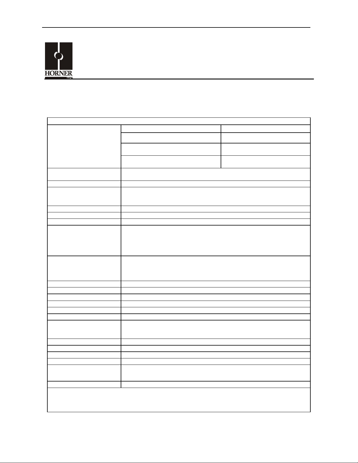
2.1 Panel Cut-Out
0.207 (5.25mm)
3.643
(92.53mm)
3.312
(84.11mm )
.280 (7.10mm)
Figure 1 – Panel Cut-Out for the OCS100/110
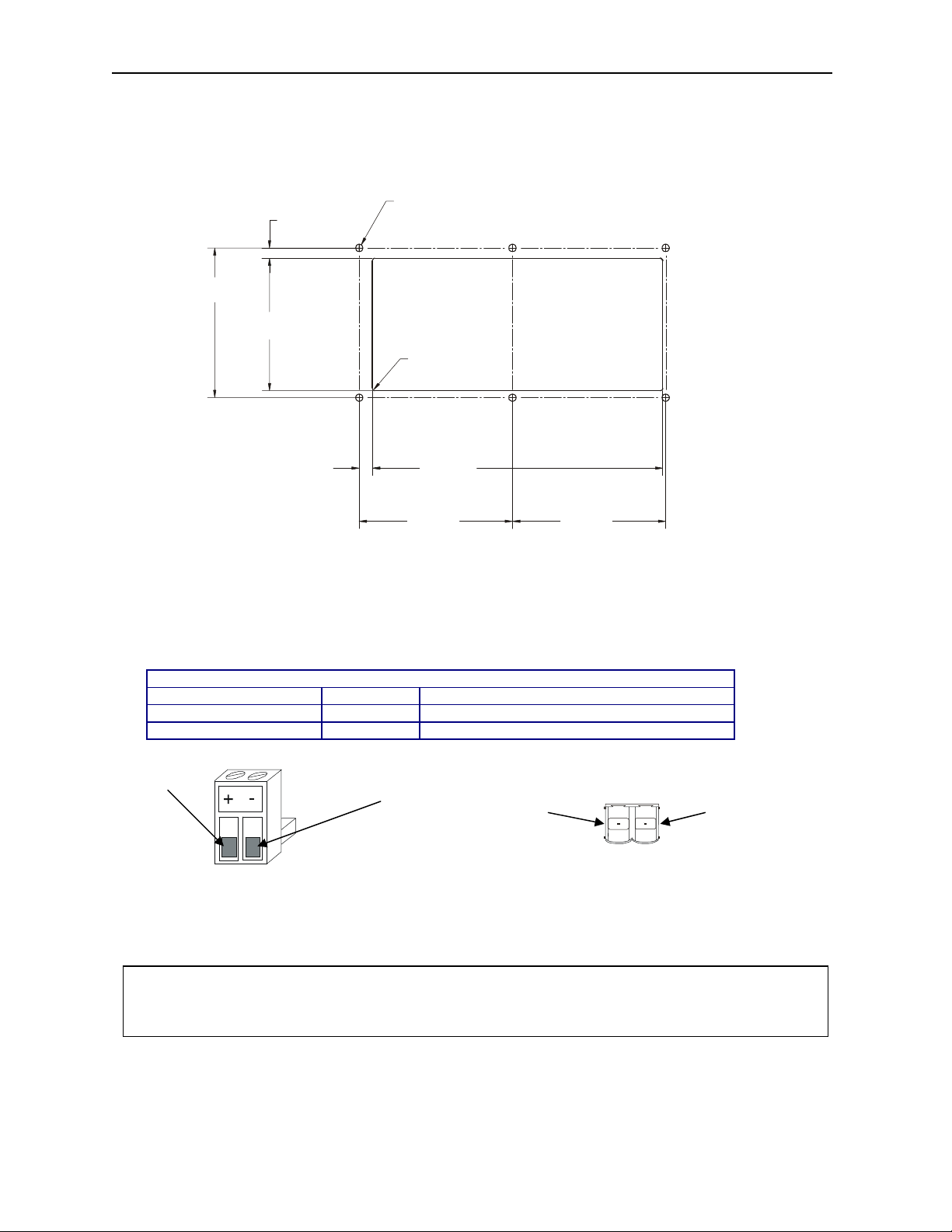
2.2 Ports, Connectors and Wiring
2.2.1 Primary Power Port
Table 2 – Primary Power Port Pins
Pin Signal Description
1 V+ Input power supply voltage
2 V- Input power supply ground
Pin 1
Figure 2 Power Connector Figure 3 As viewed looking at
(Primary Power Port) the OCS models
Note: Power Supply Voltage Range is from 10-30 VDC.
Warning: To provide maximum noise immunity and to ensure minimum EMI radiation, the V-
signal (DC power return) need to be connected to earth ground at the power supply. The user must
ensure that the power supply selected is compatible with this method of grounding.
3/16 (4.76mm) DRILL THRU
6X
.062 (1.57mm)R.
TYP.
7.151
(181.63mm)
3.730
(94.74mm)
Pin 2
3.730
(94.74mm)
001OCS023
Pin 2 Pin 1
Page 3

MAN0416-04 26 JUL 2004 PAGE 3
2.2.2 CAN / DeviceNet Network Port and Wiring
a. Network Connector
Table 3 – CAN Port Pins
Pin Signal Description
1 V- Power 2 CN_L Signal 3 SHLD Shield
4 CN_H Signal +
5 V+ Power +
Figure 4– Network Connector Figure 5– As viewed at the OCS
Warning: To provide maximum noise immunity and to ensure minimum EMI radiation, the V-
signal (DC power return) need to be connected to earth ground at the power supply. The user must
ensure that the power supply selected is compatible with this method of grounding.
b. Grounding
1 2 3 4 5
DC Power
Frame
(Earth)
Ground
V+
CN_H
SHLD
CN_L
V-
Supply
+-
+ -
OCS
Connect DC V- to earth ground at the power supply.
Figure 6– Grounding Method
(OCS shown in this example.)
1 2 3 4 5
V-
SHLD
CN_L
V+
CN_H
Page 4

PAGE 4 26 JUL 2004 MAN0416-04
2.2.3 RS-232 Programming Port and Wiring
Table 4– RS-232 Port Pins
Pin Signal Description Direction
1 DCD Always high Out
2 RXD Received Data Out
3 TXD Transmitted Data In
4 DTR Data Terminal Ready In
5 GND Ground 6 DSR Data Set Ready Out
7 RTS Request to Send In
8 CTS Clear to Send Out
9 RI Ring Indicate Out
Pin 1
Pin 9
Figure 7 – RS-232 Port
The OCS units feature an RS-232 port (Programming/Debug) for connection to a personal computer.
This port is used for the purposes of OCS programming, configuring, monitoring, and debugging. This
port can also be used for general ladder logic controlled serial communications to printers, modems,
terminals, etc. When ladder has control of this port, it is not available for programming or debugging. The
wiring diagram for the RS-232 port is shown in Figure 8. If a permanent connection is to be made
between the OCS and the personal computer, the use of a shielded, multiple conducto r wire with a
maximum length of 15.24 meters (50 feet) enables proper performance.
OCS RS-232 9-PIN PC COM
1 DCD
DCD 1
RXD 2
TXD 3
DTR 4
GND 5
DSR 6
RTS 7
CTS 8
RI 9
SHIELDED MULTI CONDUCTOR
2 RXD
3 TXD
4 DTR
5 GND
6 DSR
7 RTS
8 CTS
9 RI
DB9
MALE
15.24 METERS MAX
(50 FEET MAX)
DB9
FEMALE
Figure 8- OCS to PC Wiring Diagram
Page 5

MAN0416-04 26 JUL 2004 PAGE 5
3 SAFETY
All applicable codes and standards need to be followed in the installation of this product.
4 TECHNICAL ASSISTANCE
For technical manual updates and assistance, contact Technical Support at the following locations:
North America:
(317) 916-4274 or visit our website at www.heapg.com.
Europe:
(+) 353-21-4321-266 or visit our website at www.horner-apg.com
Page 6

PAGE 6 26 JUL 2004 MAN0416-04
NOTES
 Loading...