

Horner APG SmartBlock User Manual
1. SPECIFICATIONS
DIQ880 & DIQ881 Digital DC Inputs
DIQ880 Digital Relay Outputs
Inputs per Module
8
Outputs per Module
8 relay
Commons per Module
1
Commons per Module
8
Input Voltage Range
12 VDC / 24 VDC
Max. Output Current per Relay
3A @ 250 VAC, resistive
Absolute Max. Voltage
35 VDC max.
Max. Total Output Current
25A continuous
Input Impedance
10KΩ
Max. Output Voltage
275 VAC, 30 VDC
Input Current
Positive Logic
Negative Logic Response Time
Network Time + 10ms
Current Max. Upper Threshold
0.8mA
-1.6mA* Max Switched Power
1250VA, 150W
Current Min. Lower Threshold
0.3mA
-2.1mA*
Contact Isolation to Bus/Ground Power
1000 VAC
Voltage Max. Upper Threshold
8 VDC
Max. Voltage Drop at Rated Current
0.5V
Voltage Min. Lower Threshold
3 VDC
Expected Life
No load: 5,000,000
Rated load: 100,000
DIQ881 Digital DC Outputs
Max. Switching Rate
300 CPM @ no load
20 CPM @ rated load
Outputs per Module
8
Commons per Module
1 Type
Mechanical Contact
Output Type
Sourcing, active pull-down
Max. Output Current per Point
2.5A
General Specifications
Max. Total Output Current
10A
Voltage Input (V+)
10-30 VDC
Output Supply Voltage (VS)
9-30VDC
Relative Humidity
5 to 95% non-condensing
Response Time
Network Time + 10ms
Required Power (Steady State)
2W (80mA @ 24 VDC)
Voltage Drop @ Rated Current
1V
Required Power (InRush)
DC Switched: 12A 50μS
AC Switched: 120mA 10ms
Protection
Short circuit, Overtemp,
Automatic Reset
Operating Temperature
0⁰ to 60⁰ C
Max. Switching Rate
Limited by message rate
Weight
12 oz. / 340 g
*24VDC Supply Voltage
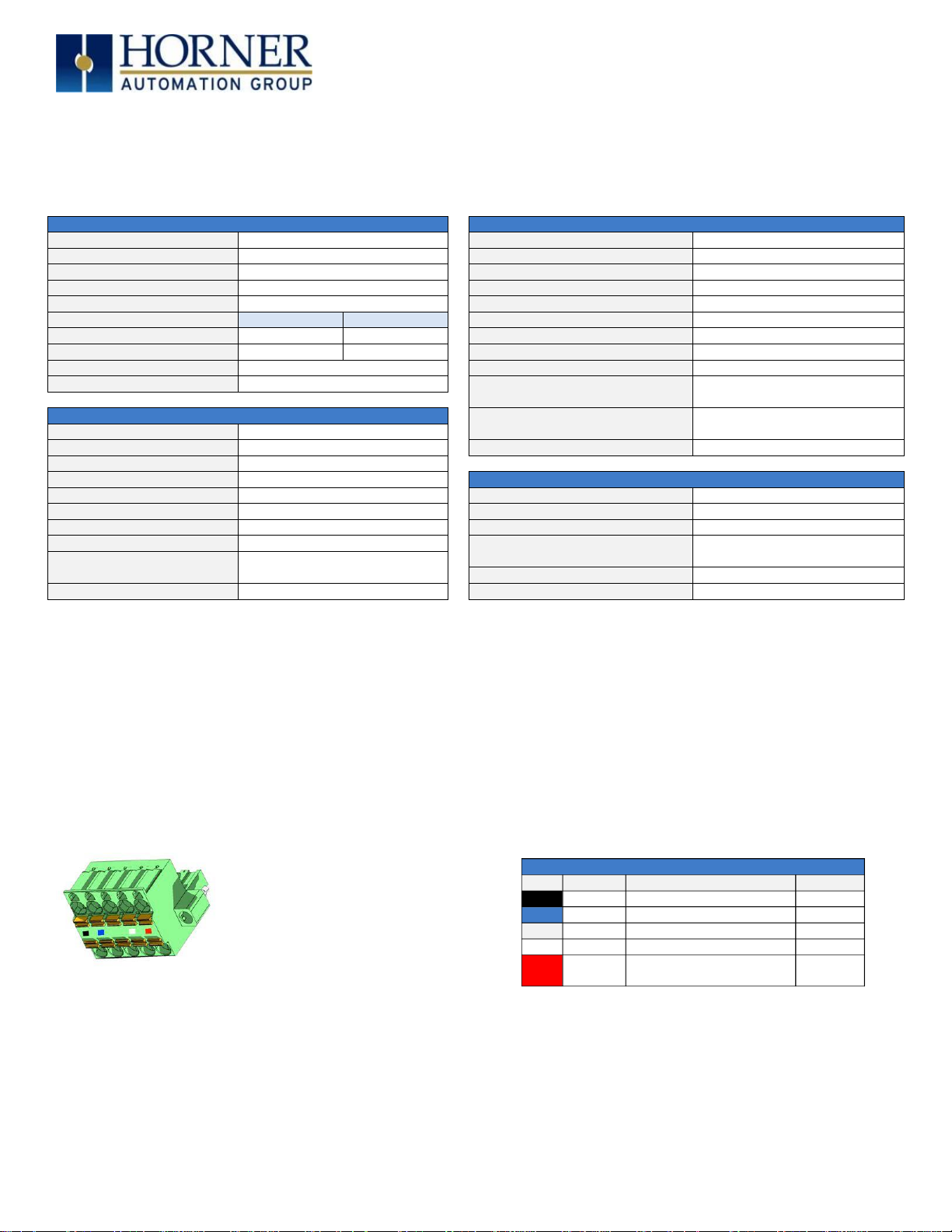
CAN Network & Power Port Pin Assignments
Pin
Signal
Signal Descriptions
Direction
1
V‒
CAN & Device Ground – Black
‒ 2 CN_L
CAN Data Low - Blue
In/Out
3
SHLD
Shield Ground - None
‒
4
CN_H
CAN Data High - White
In/Out
Positive DC Voltage
Input (10-30 VDC) - Red
MAN0980-01-EN
Specifications/Installation
SmartBlock I/O Module
HE579DIQ880 ‒ 8DC Inputs, 8 Relay Outputs
HE579DIQ881 - 8DC Inputs, 8 DC Outputs
NOTES:
A. I/O common pins, C, are internally connected to the power supply negative.
B. Digital inputs are configurable for positive or negative logic using Cscape.
C. When configured for positive logic, the inputs are pulled down to common by a 10K resistor. When an input is open or low, the
associated LED is OFF and the associated OCS register bit is 0. When an input is driven high above the threshold level, the
associated LED turns ON, and the associated OCS register bit is 1.
D. When configured for negative logic, the inputs are pulled up to the positive supply voltage, V+, by a 10K resistor. When an
input is open or high, the associated LED is OFF and the associated OCS register bit is 0. When an input is driven low, below
the threshold, the associated LED turns ON, and the associated OCS register bit is 1.
2. CAN Wiring
CAN Network & Power Connector
Torque rating 4.5 – 7 Lb.-In. (0.50 – 0.78 N-m)
Network, Power, and Grounding:
A single 5 pin connector is used to make both a network connection and power input. A quality class 2 power supply should be used for
this product. If the power is run with the network cable, care must be taken such that the voltage does not drop below the lower supply
limit on longer runs.
A quality earth ground is required for safe and proper operation. The best ground is achieved by screwing the lower left grounding
location into a grounded back plate. Alternately, a ground can be connected to the spade lug.
Please see Horner manual MAN0799 for details on CAN wiring.
10/29/2013 No part of this publication may be reproduced without the prior agreement and written permission of Horner APG, LLC. Information in this document is subject to change without notice. Page 1 of 5
5 V+
‒
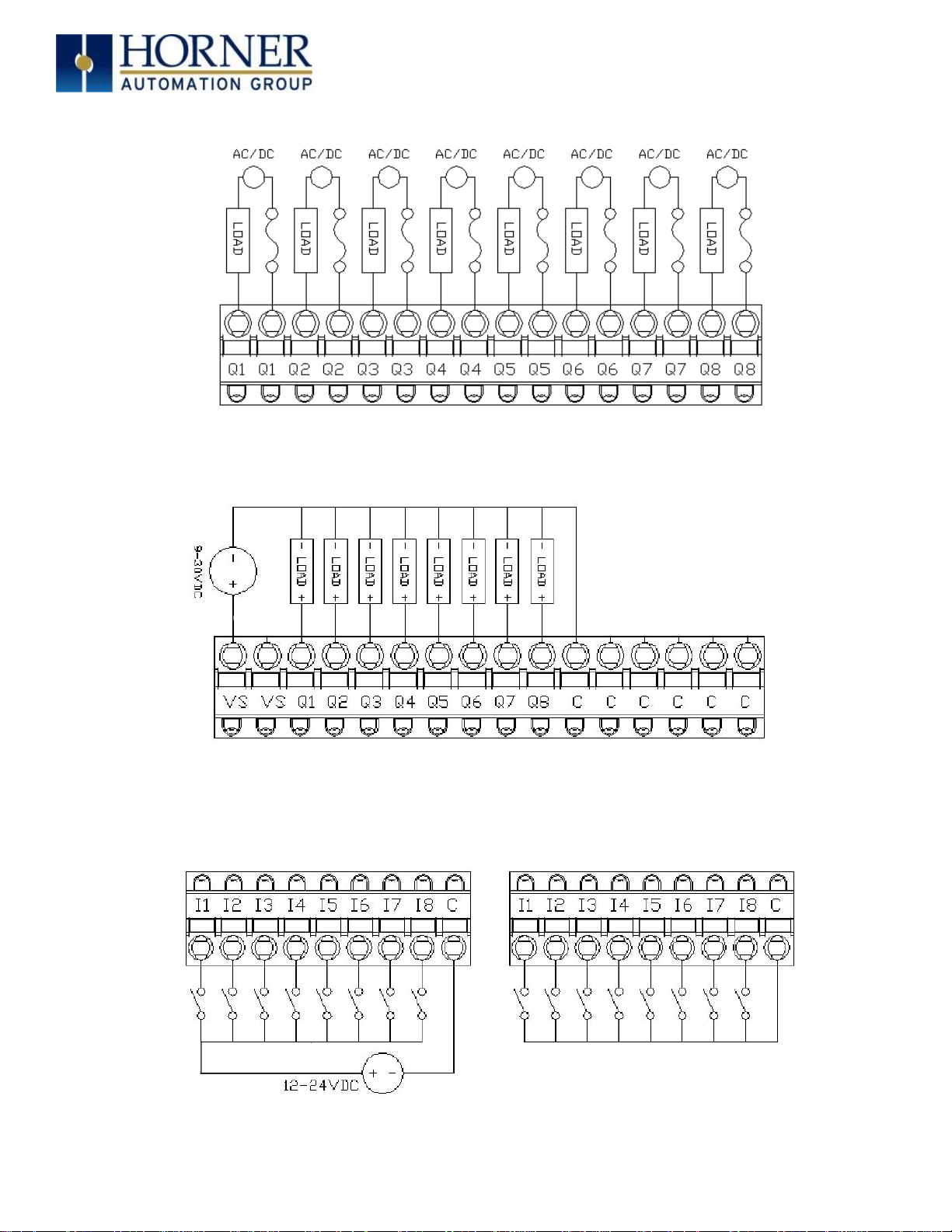
3. INTERNAL WIRING
Positive Logic
Negative Logic
MAN0980-01-EN
Specifications/Installation
Figure 1 - HE57DIQ880 Outputs
Figure 2 - He579DIQ881 Outputs
Figure 3 - HE57DIQ880/881 Inputs
10/29/2013 No part of this publication may be reproduced without the prior agreement and written permission of Horner APG, LLC. Information in this document is subject to change without notice. Page 2 of 5
 Loading...