

Page 1
MAN0265-09 10 NOV 2006 PAGE 1
HSC600
High Speed Counter
HE800HSC600 / HE-HSC600*
High Speed Cou nter Inputs
This datasheet also covers products starting with IC300.
This product also has a detailed supplement (SUP0265) available.
Sinking Pulse Outputs
* HE- denotes plastic case.
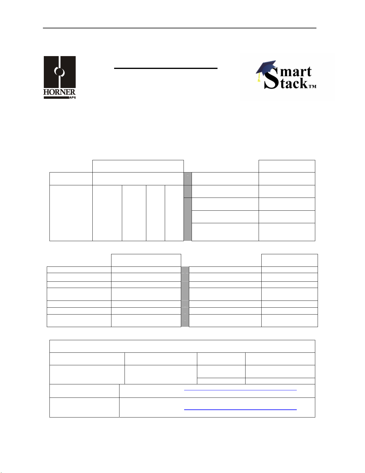
1 SPECIFICATIONS
INPUT HSC600
Inputs per
Module
Programmable
Input Voltage
Ranges
ON Voltage
Level
OFF Voltage
Level
Zero
Crossing
+ 0.1
- 0.1 + 0.8 + 4 + 8
8
TTL /
5 VDC
+ 2
12
VDC
+ 8
VDC
+ 16
OUTPUT HSC600
Outputs per Module 8 Output Protection Short Circuit
Commons per Module 1
Operating Voltage 5–35 VDC Maximum Inrush Current 600 mA. per channel
Output Type
Peak Voltage
Output Characteristics
ON Voltage Level
Sinking / 10 K Pull-Up
Negative Logic
35 VDC Max.
Current Sinking
1.5 VDC Max. @ 500 mA
0.7 VDC Max. @ 250 mA
Commons per Module 1
24
Input Type Positive Logic
Peak Voltage 35 VDC Max.
Input Impedance 10 KΩ
Input Filter
Maximum Leakage Current
Minimum Load None
OFF to ON Response
ON to OFF Response
Maximum Load Current per
Output
500 KHz, 50 KHz,
HSC600
5 KHz
HSC600
100 µA
0.3 µS.
2 µS.
0.5 A
General Specifications
Required Power
(Steady State)
Required Power (Inrush)
CE See Compliance Table at http://www.heapg.com/Support/compliance.htm
0.29 W (12.43 mA @
24 VDC)
0.44 W (18.4 mA @
24 VDC)
Relative Humidity 5–95% Non-condensing
Operating
Temperature
Weight 9.5 oz. (270 g)
0°–60° Celsius
Operating Temperature Code T4A;
UL
See Compliance Table at http://www.heapg.com/Support/compliance.htm
Information is subject to change without notice. SmartStack is a trademark of Horner APG, LLC.
Page 2
PAGE 2 10 NOV 2006 MAN0265-09
HSC600
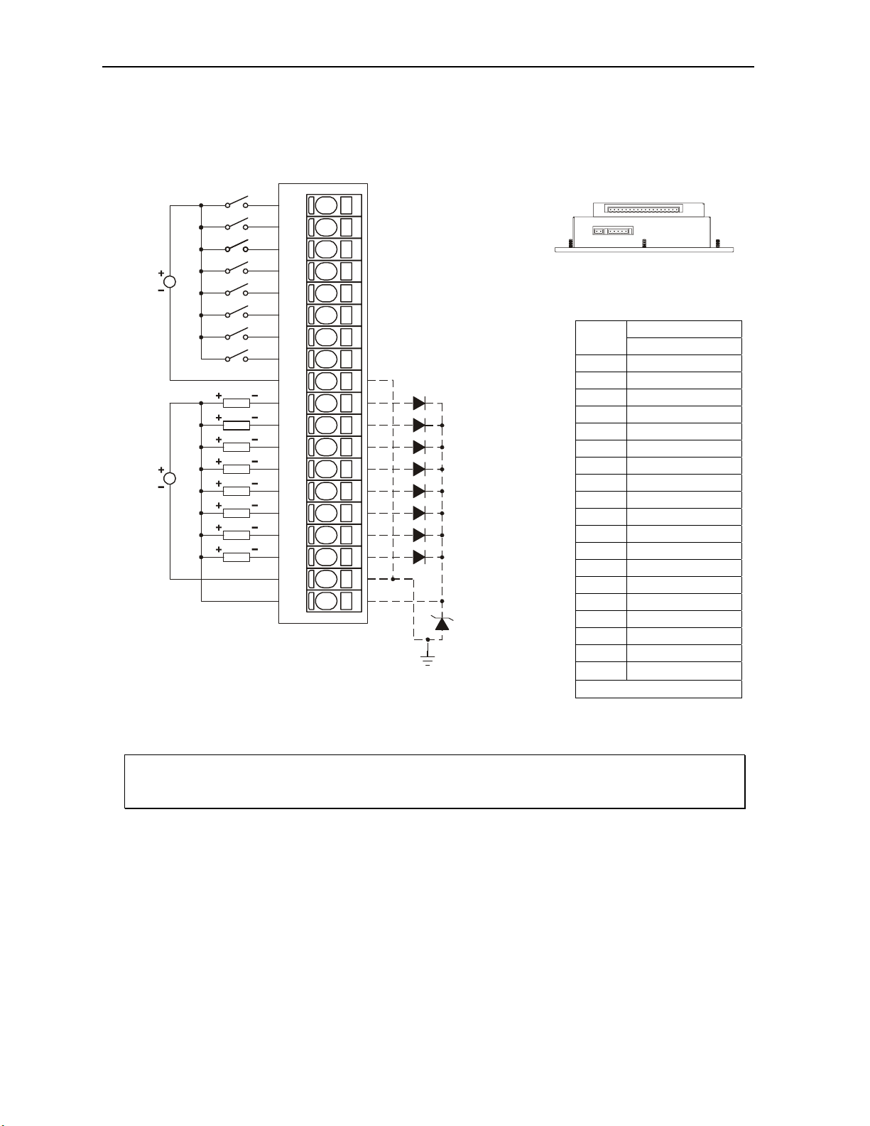
2 WIRING
0-24VDC
5-35VDC
LOAD
LOAD
LOAD
LOAD
LOAD
LOAD
LOAD
LOAD
I1
I2
I3
I4
I5
I6
I7
I8
C
Q1
Q2
Q3
Q4
Q5
Q6
Q7
Q8
VC
V+
001HSC001
*
*
OCS Bottom View – Shows
Corresponding I/O Pin
Pin
I1 Input 1
I2 Input 2
I3 Input 3
I4 Input 4
I5 Input 5
I6 Input 6
I7 Input 7
I8 Input 8
C Common
Q1 Output 1
Q2 Output 2
Q3 Output 3
Q4 Output 4
Q5 Output 5
Q6 Output 6
Q7 Output 7
Q8 Output 8
VC Common
V+ Load Voltage +
1
Internally Connected
Signal
HSC600
1
1
Warning: Wiring the positive side of the DC source to loads connected to outputs 1 through 8
and the negative side of the DC source to the output common(s) would create a Negative Logic
condition, which may be considered an unsafe practice under CE directives.
Information is subject to change without notice. SmartStack is a trademark of Horner APG, LLC.
Page 3
MAN0265-09 10 NOV 2006 PAGE 3
HSC600
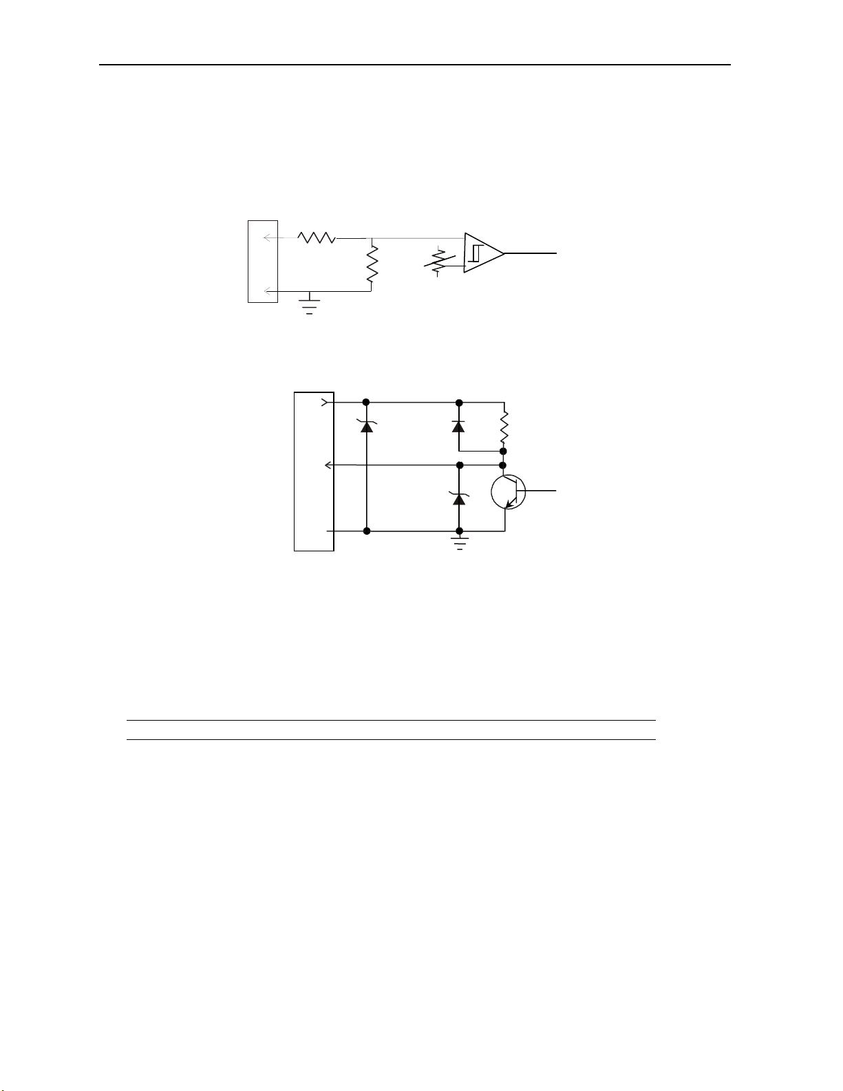
3 INTERNAL CIRCUIT SCHEMATIC
Field Side
I/O Connector
I1
SmartStack
To Controller
C
I/O Connector
V+
SmartStack
Field
Side
Q
From
Controller
VC
Specification for transient voltage suppressors (transorbs) used on output circuitry is 36 VDC, 300 W.
4 CONFIGURATION AND MODES
Note: The status of the I/O can be monitored in Cscape Software.
See the Supplement for the High Speed Counter Supplement (SUP0265) for detailed information
covering configuration and input/output modes.
Information is subject to change without notice. SmartStack is a trademark of Horner APG, LLC.
Page 4

PAGE 4 10 NOV 2006 MAN0265-09
HSC600
5 INPUT / OUTPUT CHARACTERISTICS
.125(±15%) V-A
Digital Input Chart
0
35VDC
AMPS PER CHANNEL
Derating Chart
.5
.4
.3
.2
.1
0
0 10 20 30 40 50 60 °C
32 50 68 86 104 122 140 °F
Information is subject to change without notice. SmartStack is a trademark of Horner APG, LLC.
Page 5

MAN0265-09 10 NOV 2006 PAGE 5
HSC600
6 INSTALLATION / SAFETY
Warning: Remove power from the OCS controller, CAN port, and any peripheral equipment
connected to this local system before adding or replacing this or any module.
Use the following wire type or equivalent:
• Belden 8917
• 16 AWG or larger
For detailed installation and a handy checklist
that covers panel box layout requirements and minimum
clearances, refer to the hardware manual of the controller you are using. (See the Additional References
section in this document.).
When found on the product, the following symbols specify:
Warning: Consult user documentation.
Warning: Electrical Shock Hazard.
WARNING: To avoid the risk of electric shock or burns, always connect the safety (or earth)
ground before making any other connections.
WARNING: To reduce the risk of fire, electrical shock, or physical injury it is strongly
recommended to fuse the voltage measurement inputs. Be sure to locate fuses as close to the
source as possible.
WARNING: Replace fuse with the same type and rating to provide protection against risk of fire
and shock hazards.
WARNING: In the event of repeated failure, do not replace the fuse again as a repeated failure
indicates a defective condition that will not clear by replacing the fuse.
WARNING: Only qualified electrical personnel familiar with the construction and operation of
this equipment and the hazards involved should install, adjust, operate, or service this
equipment. Read and understand this manual and other applicable manuals in their entirety
before proceeding. Failure to observe this precaution could result in severe bodily injury or loss
of life.
Information is subject to change without notice. SmartStack is a trademark of Horner APG, LLC.
Page 6

PAGE 6 10 NOV 2006 MAN0265-09
HSC600
For detailed installation and a handy checklist
that covers panel box layout requirements and minimum
clearances, refer to the hardware manual of the controller you are using. (See the Additional References
section in this document.):
• All applicable codes and standards need to be followed in the installation of this product.
• For I/O wiring (discrete), use the following wire type or equivalent: Belden 9918, 18 AWG or
larger.
Adhere to the following safety precautions whenever any type of connection is made to the module.
• Connect the green safety (earth) ground first before making any other connections.
• When connecting to electric circuits or pulse-initiating equipment, open their related breakers.
make connections to live power lines.
Do not
• Make connections to the module first; then connect to the circuit to be monitored.
• Route power wires in a safe manner in accordance with good practice and local codes.
• Wear proper personal protective equipment including safety glasses and insulated gloves
when making connections to power circuits.
• Ensure hands, shoes, and floor are dry before making any connection to a power line.
• Make sure the unit is turned OFF before making connection to terminals. Make sure all
circuits are de-energized before making connections.
• Before each use, inspect all cables for breaks or cracks in the insulation. Replace
immediately if defective.
Information is subject to change without notice. SmartStack is a trademark of Horner APG, LLC.
Page 7

MAN0265-09 10 NOV 2006 PAGE 7
HSC600
7 ADDITIONAL REFERENCES
The following information serves as a general listing of Horner controller products and other references of
interest and their corresponding manual numbers. Visit our website listed in the Technical Support section
to obtain user documentation and updates.
Note: This list is not intended for users to determine which products are appropriate for their
application; controller products differ in the features that they support. If assistance is required,
see the Technical Support section in this document.
Controller Manual Number
XLE Series (e.g., HE-XExxx) MAN0805
QX Series (e.g., HE-QXxxx) MAN0798
NX Series (e.g., HE-NXxxx) MAN0781
LX Series (e.g., LX-xxx; also covers RCS116) MAN0755
Color Touch OCS (e.g., OCSxxx) MAN0465
OCS (Operator Control Station) (e.g., OCS1xx / 2xx; Graphic
OCS250)
Remote Control Station (e.g., RCS2x0)
MiniOCS (e.g., HE500OCSxxx, HE500RCSxxx) MAN0305
Other Useful References
CAN Networks MAN0799
Cscape Programming and Reference MAN0313
Wiring Accessories and Spare Parts Manual MAN0347
DeviceNet™ Implementation SUP0326
Wiring Accessories and Spare Parts Manual MAN0347
MAN0227
Information is subject to change without notice. SmartStack is a trademark of Horner APG, LLC.
Page 8

PAGE 8 10 NOV 2006 MAN0265-09
HSC600
8 TECHNICAL SUPPORT
For assistance and manual up-dates, contact Technical Support at the following locations:
North America:
(317) 916-4274
www.heapg.com
Europe:
(+) 353-21-4321-266
www.horner-apg.com
Information is subject to change without notice. SmartStack is a trademark of Horner APG, LLC.
 Loading...