

Page 1
MAN0372-06 10 NOV 2006 PAGE 1
DQM306/406
Digital Outputs
24 VDC Out, Positive Logic
HE800DQM306 (16 Outputs) /
HE-DQM306* (16 Outputs)
HE800DQM406 (32 Outputs) /
HE-DQM406* (32 Outputs)
* HE- denotes plastic case.
1 SPECIFICATIONS
OUTPUT
Outputs per Module
Power Commons per
Module
Operating Voltage 10–30 VDC OFF to ON Response 1 ms.
Output Type Sourcing / 10 K PullDown ON to OFF Response 1 ms.
Peak Voltage 28 VDC Max. Output Characteristics Current Sourcing
Maximum Load
Current per channel
DQM306 DQM406
16 32
1 2 Minimum Load None
0.5 A Max. per output
Maximum Inrush Current per
channel
Output Protection Short Circuit
DQM306 DQM406
650 mA
General Specifications
Required Power
(Steady State)
Required Power (Inrush) Negligible Terminal Type Spring Clamp, Removable
Relative Humidity 5–95% Noncondensing Weight 9 oz. (256 g)
CE
UL
0.12 W (5 mA @ 24 VDC)
See Compliance Table at http://www.heapg.com/Support/compliance.htm
Operating
Temperature
0°–60° Celsius
Information is subject to change without notice. SmartStack is a trademark of Horner APG, LLC.
Page 2
PAGE 2 10 NOV 2006 MAN0372-06
DQM306/406
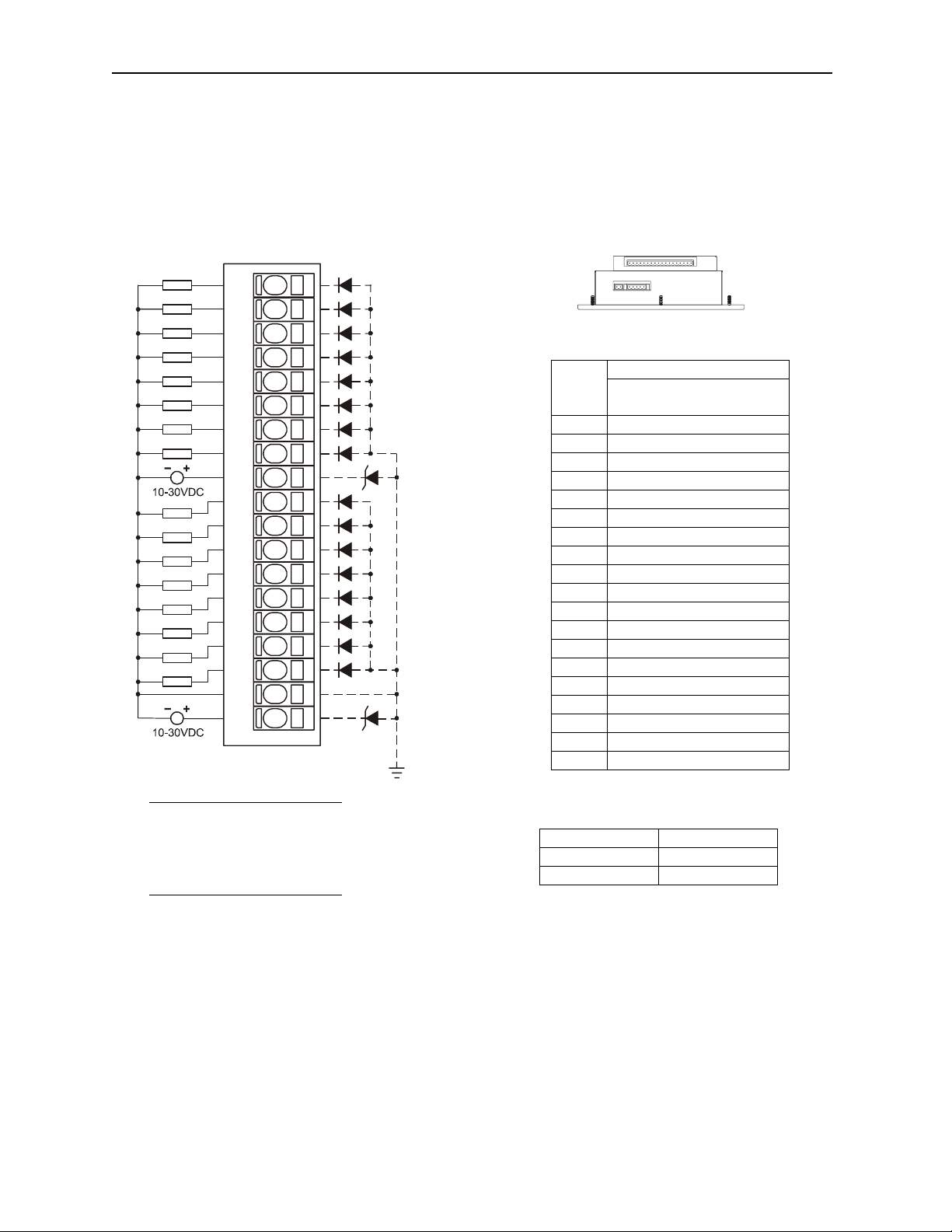
2 WIRING
2.1 Bottom Connector (Used by DQM306 and DQM406)
*
+
-
LOAD
-
-
LOAD
LOAD
-
LOAD
-
LOAD
-
LOAD
-
LOAD
-
LOAD
-
LOAD
-
LOAD
-
LOAD
-
LOAD
-
LOAD
-
LOAD
-
LOAD
-
LOAD
-
LOAD
Q1
+
+
Q2
+
Q3
+
Q4
+
Q5
+
Q6
+
Q7
+
Q8
V1
Q9
+
Q10
+
Q11
+
Q12
+
Q13
+
Q14
+
Q15
+
Q16
+
C1
V2
*
OCS Bottom View – Shows
Corresponding I/O Pin
Signal
Pin
DQM306/406
OUTPUT
Q1 Output 1
Q2 Output 2
Q3 Output 3
Q4 Output 4
Q5 Output 5
Q6 Output 6
Q7 Output 7
Q8 Output 8
V1 Load Power 1
Q9 Output 9
Q10 Output 10
Q11 Output 11
Q12 Output 12
Q13 Output 13
Q14 Output 14
Q15 Output 15
Q16 Output 16
C1 Common 1
001DQM002
V2 Load Power 2
Note: For Class I, Div. 2
operation, V1, V2, V3, and
V4 must share the same
power supply.
Load Power Outputs
1 1-8
2 9-16
Information is subject to change without notice. SmartStack is a trademark of Horner APG, LLC.
Page 3
MAN0372-06 10 NOV 2006 PAGE 3
DQM306/406
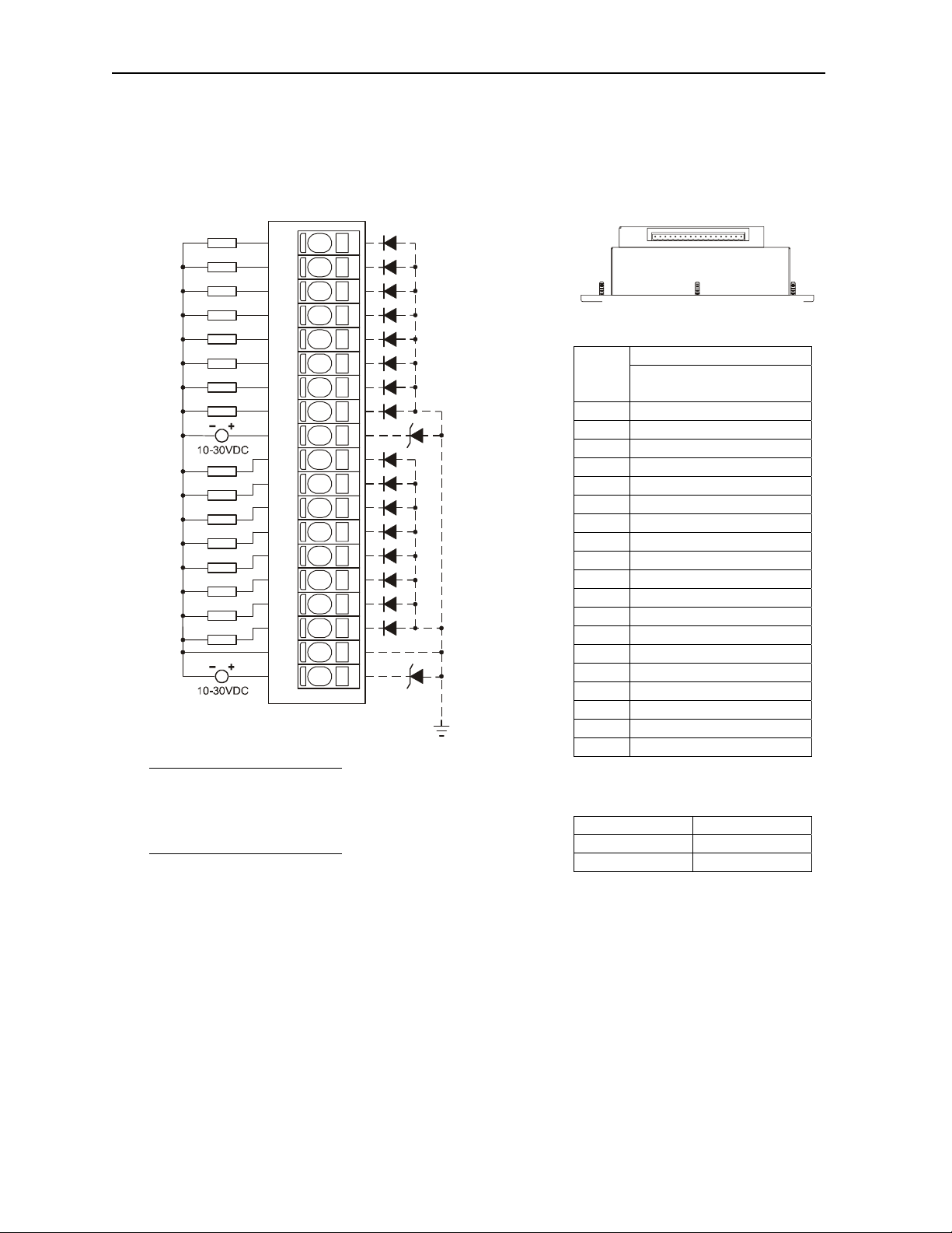
2.2 Top Connector (Used by DQM406 only)
+
-
LOAD
+
+
-
-
LOAD
LOAD
+
-
LOAD
+
-
LOAD
+
-
LOAD
+
-
LOAD
+
-
LOAD
+
-
LOAD
+
+
-
-
LOAD
LOAD
+
-
LOAD
+
-
LOAD
+
-
LOAD
+
-
LOAD
+
-
LOAD
+
-
LOAD
+
-
LOAD
Note: For Class I, Div. 2
operation, V1, V2, V3, and
V4 must share the same
power supply.
Q17
Q18
Q19
Q20
Q21
Q22
Q23
Q24
V3
Q25
Q26
Q27
Q28
Q29
Q30
Q31
Q32
C2
V4
001DQM003
*
*
OCS Top View – Shows
Corresponding I/O Pin
Signal
Pin
Q17 Output 17
Q18 Output 18
Q19 Output 19
Q20 Output 20
Q21 Output 21
Q22 Output 22
Q23 Output 23
Q24 Output 24
V3 Load Power 3
Q25 Output 25
Q26 Output 26
Q27 Output 27
Q28 Output 28
Q29 Output 29
Q30 Output 30
Q31 Output 31
Q32 Output 32
C2 Common 1
V4 Load Power 4
Load Power Outputs
3 17-24
4 25-32
DQM406
OUTPUT
Information is subject to change without notice. SmartStack is a trademark of Horner APG, LLC.
Page 4

PAGE 4 10 NOV 2006 MAN0372-06
DQM306/406
3 INTERNAL WIRING
I/O Connector
V+
Field
Side
Q
C
SmartStack
See
Note 1
See
Note 2
From
Controller
Note 1: Specification for transient voltage suppressors (transorbs) used on output
circuitry is 36 V, 300 W.
Note 2: Specification for transient voltage suppressors (transorbs) used on output
circuitry is 33 V, 300 W.
4 CONFIGURATION
Note: The status of the I/O can be monitored in Cscape Software.
Preliminary configuration procedures that apply to SmartStack™ Modules are contained in the hardware
manual of the controller you are using. Refer to the Additional References
listing of hardware manuals.
Selecting the I/O Map tab provides information about the I/O registers, which are assigned to a specific
SmartStack™ Module and where the module is located in the point map. The I/O Map is determined by
the model number and location within the SmartStack™. The I/O Map is not
The Module Setup is used in applications where it is necessary to change the default states of the
outputs when the controller (e.g., OCS100) enters idle/stop mode. The default turns the outputs OFF
when the controller enters idle/stop mode. By selecting the Module Setup tab, each output can be set to
either turn ON, turn OFF or to hold the last state. Generally, most applications use the default settings.
Warning: The default turns the outputs OFF when the controller enters idle/stop mode. To
avoid injury of personnel or damages to equipment, exercise extreme caution when changing
the default setting using the Module Setup tab.
section in this data sheet for a
edited by the user.
Information is subject to change without notice. SmartStack is a trademark of Horner APG, LLC.
Page 5

MAN0372-06 10 NOV 2006 PAGE 5
DQM306/406
5 INSTALLATION / SAFETY
Warning: Remove power from the OCS controller, CAN port, and any peripheral equipment
connected to this local system before adding or replacing this or any module.
Use the following wire type or equivalent:
• Belden 8917
• 16 AWG or larger
For detailed installation and a handy checklist
that covers panel box layout requirements and minimum
clearances, refer to the hardware manual of the controller you are using. (See the Additional References
section in this document.).
When found on the product, the following symbols specify:
Warning: Consult user documentation.
Warning: Electrical Shock Hazard.
WARNING: To avoid the risk of electric shock or burns, always connect the safety (or earth)
ground before making any other connections.
WARNING: To reduce the risk of fire, electrical shock, or physical injury it is strongly
recommended to fuse the voltage measurement inputs. Be sure to locate fuses as close to the
source as possible.
WARNING: Replace fuse with the same type and rating to provide protection against risk of fire
and shock hazards.
WARNING: In the event of repeated failure, do not replace the fuse again as a repeated failure
indicates a defective condition that will not clear by replacing the fuse.
WARNING: Only qualified electrical personnel familiar with the construction and operation of
this equipment and the hazards involved should install, adjust, operate, or service this
equipment. Read and understand this manual and other applicable manuals in th eir entirety
before proceeding. Failure to observe this precaution could result in severe bodily injury or loss
of life.
Information is subject to change without notice. SmartStack is a trademark of Horner APG, LLC.
Page 6

PAGE 6 10 NOV 2006 MAN0372-06
DQM306/406
For detailed installation and a handy checklist
that covers panel box layout requirements and minimum
clearances, refer to the hardware manual of the controller you are using. (See the Additional References
section in this document.):
• All applicable codes and standards need to be followed in the installation of this product.
• For I/O wiring (discrete), use the following wire type or equivalent: Belden 9918, 18 AWG or
larger.
Adhere to the following safety precautions whenever any type of connection is made to the module.
• Connect the green safety (earth) ground first before making any other connections.
• When connecting to electric circuits or pulse-initiating equipment, open their related breakers.
make connections to live power lines.
Do not
• Make connections to the module first; then connect to the circuit to be monitored.
• Route power wires in a safe manner in accordance with good practice and local codes.
• Wear proper personal protective equipment including safety glasses an d insulated gloves
when making connections to power circuits.
• Ensure hands, shoes, and floor are dry before making any connection to a power line.
• Make sure the unit is turned OFF before making connection to terminals. Make sure all
circuits are de-energized before making connections.
• Before each use, inspect all cables for breaks or cra cks in the in sulation. Replace
immediately if defective.
Information is subject to change without notice. SmartStack is a trademark of Horner APG, LLC.
Page 7

MAN0372-06 10 NOV 2006 PAGE 7
DQM306/406
6 ADDITIONAL REFERENCES
The following information serves as a general listing of Horner controller products and other references of
interest and their corresponding manual numbers. Visit our website listed in the Technical Support section
to obtain user documentation and updates.
Note: This list is not intended for users to determine which products are appropriate for their
application; controller products differ in the features that they support. If assistance is required,
see the Technical Support section in this document.
Controller Manual Number
XLE Series (e.g., HE-XExxx) MAN0805
QX Series (e.g., HE-QXxxx) MAN0798
NX Series (e.g., HE-NXxxx) MAN0781
LX Series (e.g., LX-xxx; also covers RCS116) MAN0755
Color Touch OCS (e.g., OCSxxx) MAN0465
OCS (Operator Control Station) (e.g., OCS1xx / 2xx; Graphic
OCS250)
Remote Control Station (e.g., RCS2x0)
MiniOCS (e.g., HE500OCSxxx, HE500RCSxxx) MAN0305
Other Useful References
CAN Networks MAN0799
Cscape Programming and Reference MAN0313
Wiring Accessories and Spare Parts Manual MAN0347
DeviceNet™ Implementation SUP0326
Wiring Accessories and Spare Parts Manual MAN0347
MAN0227
Information is subject to change without notice. SmartStack is a trademark of Horner APG, LLC.
Page 8

PAGE 8 10 NOV 2006 MAN0372-06
DQM306/406
7 TECHNICAL SUPPORT
For assistance and manual up-dates, contact Technical Support at the following locations:
North America:+
(317) 916-4274
www.heapg.com
Europe:
(+) 353-21-4321-266
www.horner-apg.com
Information is subject to change without notice. SmartStack is a trademark of Horner APG, LLC.
 Loading...