

Page 1
MAN0234-09 10 NOV 2006 PAGE 1
ADC010-110
+/- 10 V Analog Input
Module
HE800ADC010 / HE800ADC110
HE-ADC010* / HE-ADC110*
This datasheet also covers products starting with IC300.
12-Bit Resolution
* HE-denotes plastic case.
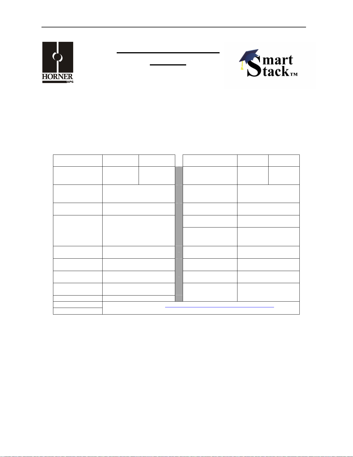
1 SPECIFICATIONS
Number of
Channels
Input Ranges
(Including overrange)
Resolution
Input Impedance
Maximum Error at
25°C
Required Power
(Steady State)
Required Power
(Inrush)
Maximum OverVoltage
Digital Filtering Yes
CE
UL
ADC010 ADC110
2 4
±10.23 VDC; ±5.11,
0 - +10.23, 0 - +5.11
12-Bits
10 MΩ <12 VDC or
6 MΩ >12 VDC Nom.
0.05% Full Scale Conversion Time
.09 W (4.1 mA @ 24 VDC)
Negligible
350 VDC Max.
See Compliance Table at http://www.heapg.com/Support/compliance.htm
Analog Inputs
Operating
Additional error for
ADC010 ADC110
Input Points
Required
External Power
Supply
Converter Type
Temperature
temperatures other
than 25°C
(PLC Update Rate)
Relative Humidity 5–95% Non-condensing
Terminal Type
Weight 9 oz. (256 g)
2 4
None
Successive
Approximation
0°–60° Celsius
0.005% / °C
Set by PLC Scan Time
Spring Clamp,
Removable
Information is subject to change without notice. SmartStack is a trademark of Horner APG, LLC.
Page 2
PAGE 2 10 NOV 2006 MAN0234-09
ADC010-110
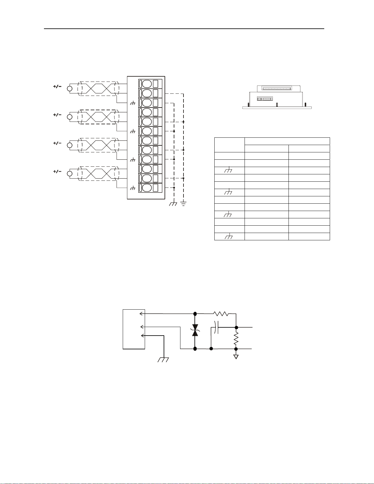
2 WIRING
V
V
INPU T
INPU T
1+
1-
*
*
2+
2-
INPU T
V
OCS Bottom View – Shows
Corresponding I/O Pin Location
INPU T
V
3+
3-
ADC110 ADC010
Signal
1+ Channel 1+ Channel 1+
1- Common Common
INPU T
V
4+
4-
Shield Shield
2+ Channel 2+ Channel 2+
2- Common Common
Shield Shield
3+ Channel 3+
001ADC001-R1
3- Common
Shield
4+ Channel 4+
4- Common
Shield
3 INTERNAL CIRCUIT SCHEMATIC
Field
Side
I/O Connector
1+
1-
Gnd
Shield
SmartStack
To
Controller
Information is subject to change without notice. SmartStack is a trademark of Horner APG, LLC.
.
Page 3
MAN0234-09 10 NOV 2006 PAGE 3
ADC010-110
4 CONFIGURATION
Note: The status of the I/O can be monitored in Cscape Software.
Preliminary configuration procedures that apply to SmartStack™ Modules are contained in the hardware
manual of the controller you are using. Refer to the Additional References section in this data sheet for a
listing of hardware manuals.
Selecting the I/O Map tab provides information about the I/O registers, which are assigned to a specific
SmartStack™ Module and where the module is located in the point map. The I/O Map is determined by
the model number and location within the SmartStack™. The I/O Map is not
edited by the user.
Module Setup Tab
a) Input range for each channel may be selected independently.
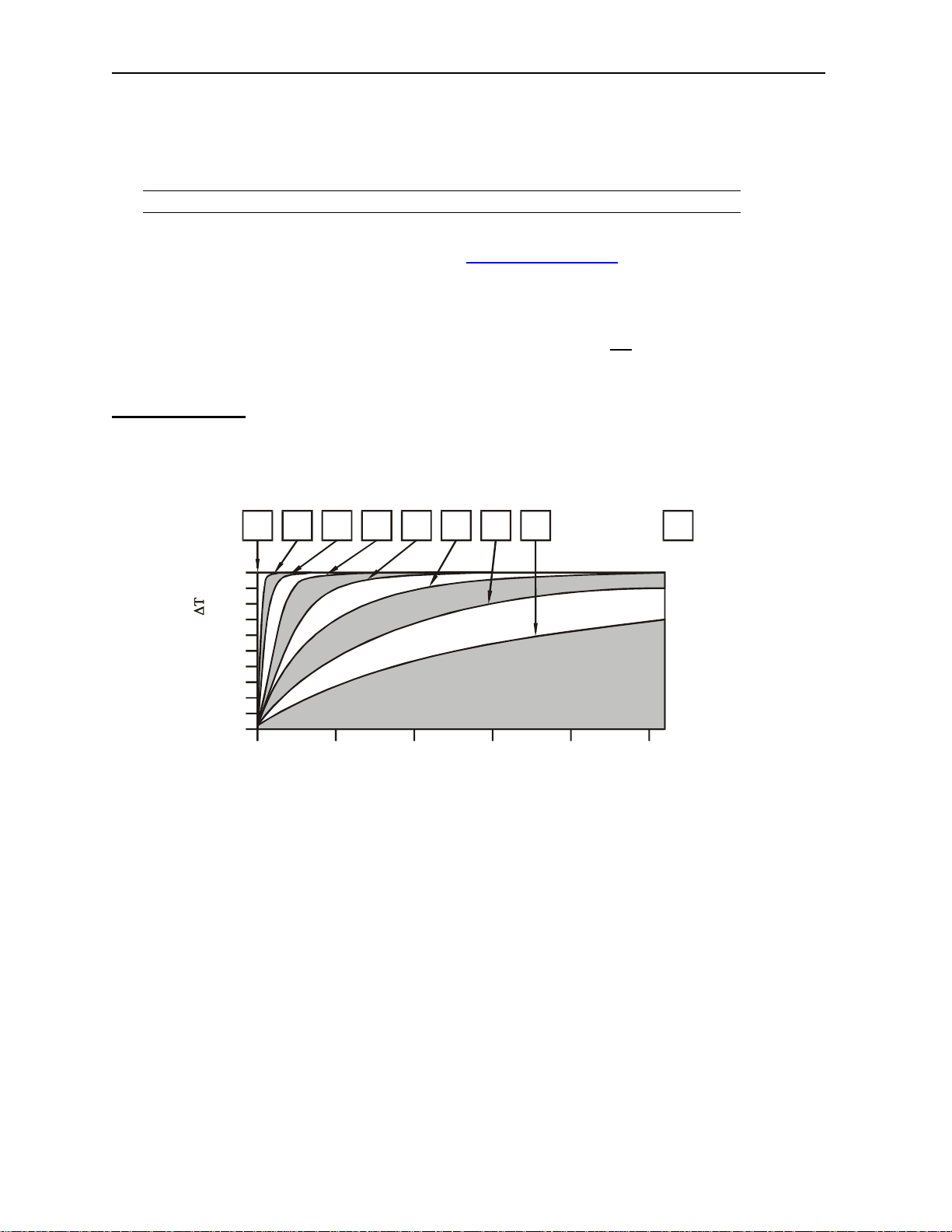
b) Filter Constant sets the level of digital filtering according to the following chart.
1
2 3 4 5 60 7
%Complete [ ]
100
90
80
70
60
50
40
30
20
10
0
60
Filter
Constant
10040 8020
Scans0
Digital Filtering: The illustration above demonstrates the effect of digital filtering (set with Filter Constant)
on module response to a temperature change.
Information is subject to change without notice. SmartStack is a trademark of Horner APG, LLC.
Page 4

PAGE 4 10 NOV 2006 MAN0234-09
ADC010-110
5 INPUT CONVERSION FACTOR
The following table describes how real-world inputs are scaled into the controller. Given a known input
voltage, the data value is configured by using the conversion factor from the table. The following formula
is used:
Data = Voltage In (Vin) / Conversion Factor
Example: The user selects a voltage range of 0 to +5 VDC:
1) The known input voltage is 3 VDC.
2) Using the table, the conversion factor for the voltage range of 0 to +5 VDC is .00015625.
3) To determine the data value, the formula is used:
Data = Vin / Conversion Factor
19200 = 3 VDC / 0.00015625
Conversion of Real-World Inputs into Controller
Selected Voltage
0 to +5.00 VDC
0 to +10.00 VDC
Range
+/-5.00 VDC
+/-10.00 VDC
Voltage In (Vin) VDC Data Out Conversion Factor
+5.11 32704
+5.00 32000
0.00 0
NA NA
NA NA
+10.23 32736
+10.00 32000
0.00 0
NA NA
NA NA
+5.11 32704
+5.00 32000
0 0
-5.00 -32000
-5.11 -32704
+10.23 32736
+10.00 32000
0 0
-10.00 -32000
-10.23 -32736
0.00015625
0.0003125
0.00015625
0.0003125
Information is subject to change without notice. SmartStack is a trademark of Horner APG, LLC.
.
Page 5

MAN0234-09 10 NOV 2006 PAGE 5
ADC010-110
6 INSTALLATION / SAFETY
Warning: Remove power from the OCS controller, CAN port, and any peripheral equipment
connected to this local system before adding or replacing this or any module.
a) All applicable codes and standards should be followed in the installation of this product.
b) Shielded, twisted-pair wiring should be used for best performance.
c) Shields may be terminated at the module terminal strip.
d) In severe applications, shields should be tied directly to the ground block within the panel.
e) Use the following wire type or equivalent:
Belden 8441
For detailed installation and a handy checklist
that covers panel box layout requirements and minimum
clearances, refer to the hardware manual of the controller you are using. (See the Additional References
section in this document.).
When found on the product, the following symbols specify:
Warning: Consult user documentation.
Warning: Electrical Shock Hazard.
WARNING: To avoid the risk of electric shock or burns, always connect the safety (or earth)
ground before making any other connections.
WARNING: To reduce the risk of fire, electrical shock, or physical injury it is strongly
recommended to fuse the voltage measurement inputs. Be sure to locate fuses as close to the
source as possible.
WARNING: Replace fuse with the same type and rating to provide protection against risk of fire
and shock hazards.
WARNING: In the event of repeated failure, do not replace the fuse again as a repeated failure
indicates a defective condition that will not clear by replacing the fuse.
WARNING: Only qualified electrical personnel familiar with the construction and operation of
this equipment and the hazards involved should install, adjust, operate, or service this
equipment. Read and understand this manual and other applicable manuals in their entirety
before proceeding. Failure to observe this precaution could result in severe bodily injury or loss
of life.
Information is subject to change without notice. SmartStack is a trademark of Horner APG, LLC.
Page 6

PAGE 6 10 NOV 2006 MAN0234-09
ADC010-110
For detailed installation and a handy checklist
that covers panel box layout requirements and minimum
clearances, refer to the hardware manual of the controller you are using. (See the Additional References
section in this document.):
• All applicable codes and standards need to be followed in the installation of this product.
• For I/O wiring (discrete), use the following wire type or equivalent: Belden 9918, 18 AWG or
larger.
Adhere to the following safety precautions whenever any type of connection is made to the module.
• Connect the green safety (earth) ground first before making any other connections.
• When connecting to electric circuits or pulse-initiating equipment, open their related breakers.
make connections to live power lines.
Do not
• Make connections to the module first; then connect to the circuit to be monitored.
• Route power wires in a safe manner in accordance with good practice and local codes.
• Wear proper personal protective equipment including safety glasses and insulated gloves
when making connections to power circuits.
• Ensure hands, shoes, and floor are dry before making any connection to a power line.
• Make sure the unit is turned OFF before making connection to terminals. Make sure all
circuits are de-energized before making connections.
• Before each use, inspect all cables for breaks or cracks in the insulation. Replace
immediately if defective.
Information is subject to change without notice. SmartStack is a trademark of Horner APG, LLC.
.
Page 7

MAN0234-09 10 NOV 2006 PAGE 7
ADC010-110
7 ADDITIONAL REFERENCES
The following information serves as a general listing of Horner controller products and other references of
interest and their corresponding manual numbers. Visit our website listed in the Technical Support section
to obtain user documentation and updates.
Note: This list is not intended for users to determine which products are appropriate for their
application; controller products differ in the features that they support. If assistance is required,
see the Technical Support section in this document.
Controller Manual Number
XLE Series (e.g., HE-XExxx) MAN0805
QX Series (e.g., HE-QXxxx) MAN0798
NX Series (e.g., HE-NXxxx) MAN0781
LX Series (e.g., LX-xxx; also covers RCS116) MAN0755
Color Touch OCS (e.g., OCSxxx) MAN0465
OCS (Operator Control Station) (e.g., OCS1xx / 2xx; Graphic
OCS250)
Remote Control Station (e.g., RCS2x0)
MiniOCS (e.g., HE500OCSxxx, HE500RCSxxx) MAN0305
Other Useful References
CAN Networks MAN0799
Cscape Programming and Reference MAN0313
Wiring Accessories and Spare Parts Manual MAN0347
DeviceNet™ Implementation SUP0326
Wiring Accessories and Spare Parts Manual MAN0347
MAN0227
8 TECHNICAL SUPPORT
For assistance and manual up-dates, contact Technical Support at the following locations:
North America:+
(317) 916-4274
www.heapg.com
Europe:
(+) 353-21-4321-266
www.horner-apg.com
Information is subject to change without notice. SmartStack is a trademark of Horner APG, LLC.
Page 8

PAGE 8 10 NOV 2006 MAN0234-09
ADC010-110
NOTES
Information is subject to change without notice. SmartStack is a trademark of Horner APG, LLC.
.
 Loading...