

Page 1
MAN0932-02-EN Specifications / Installation
__________________________________________________________________________________________________________________________________________________________________
1/3/2011 Page 1 of 1
1 Specifications
Specifications
DAC101
DAC106
Number of Channels
4
Output Range(s)
0-10V
0-20mA, 4-20mA
Absolute Maximum Output
DC ±15V
DC ±25mA
Resolution
12-Bit (2.5mV)
12-bit (5uA, 4uA)
Maximum Load
>2kΩ
<510Ω
Accuracy
< +/-0.5%
Isolation
500V (backplane)
Conversion Time
1mS/ch
Backplane Power Consumed
110mA @ 5V
External Power Required
62mA @ 24V
120mA @ 24V
Terminal Type
Screw Type, Removable 11-posn
Optional Spring-clamp Plug
HE599TRM011
Storage Temp.
-25° to 70° Celsius
Operating Temp.
-0° to 55° Celsius
Relative Humidity
5 to 95% Non-condensing
Dimensions WxHxD
20mm x 90mm x 60mm
0.79” x 3.54” x 2.36”
Weight
64g (2.3 oz.)
70g (2.5oz.)
CE & UL Compliance
CE, UL & C-UL
2 Wiring – I/O
3 Configuration DATA
The SmartRail Analog Output modules have a variety of parameters configured on a channel-bychannel basis. These parameters are set using Cscape (9.1 or later), and are listed below:
Cscape Configuration Data – Selectable per channel
Parameter
DAC101
DAC106
Hold Last State
Go to Minimum
Go to Mid-range
Hold Last State
Go to Maximum
4-20mA
Analog Output Range
0-10V
0-20mA
3.1 Output Scaling
The SmartRail Analog Outputs scale digital values from 0-4000, to the analog value (0-10V, 020mA, or 4-20mA). For every digital count the output is incremented, the analog output value will
increment an appropriate amount (2.5mV for 0-10V, 5uA for 0-20mA, 4uA for 4-20mA).
4 Installation / safety
a. All applicable codes and standards should be followed in the installation of this product.
b. Shielded, twisted-pair wiring should be used for best performance.
c. Shields should be grounded at one end only, preferably at the end providing the best noise
shunting.
d. Use the following wire type or equivalent: Belden 8441.
For detailed installation and a handy checklist that covers panel box layout requirements and
minimum clearances, refer to the hardware manual of the controller you are using.
When found on the product, the following symbols specify:
7 Technical Support
Technical Support at the following locations:
North America:
Tel: 317 916-4274
Fax: 317 639-4279
Web: http://www.heapg.com
Email: techsppt@heapg.com
Europe:
Tel: +353-21-4321266
Fax: +353-21-4321826
Web: http://www.horner-apg.com
Email: tech.support@horner-apg.com
DAC LED Status Indication
LED
Meaning
ON = Normal Operation
FLASH = I/O Error
RUN
OFF = No Power or I/O Error
SmartRail
0-10V or 4-20mA Analog Output Modules
HE599DAC101 (voltage) & HE599DAC106 (current)
12-Bit Resolution
No part of this publication may be reproduced without the prior agreement and written
permission of Horner APG, Inc. Information in this document is subject to change without
notice.
Warning: Remove power from the OCS controller and any peripheral equipment connected
to this local system before adding or replacing this or any module.
Warning: Consult
user documentation.
Warning: Electrical
Shock Hazard.
+
-
24VDC
N.C.
-
CH4
+
-
CH3
+
-
CH2
+
-
CH1
+
24VDC @ 120mA
External Power
SHIELD GROUNDED
AT O NE EN D O NLY
+
-
+
-
LOAD
+
-
LOAD
+
-
LOAD
+
-
LOAD
DAC106
DAC101
0-20mA
<510 OHM
LOAD
0-10V
>2k OHM
LOAD
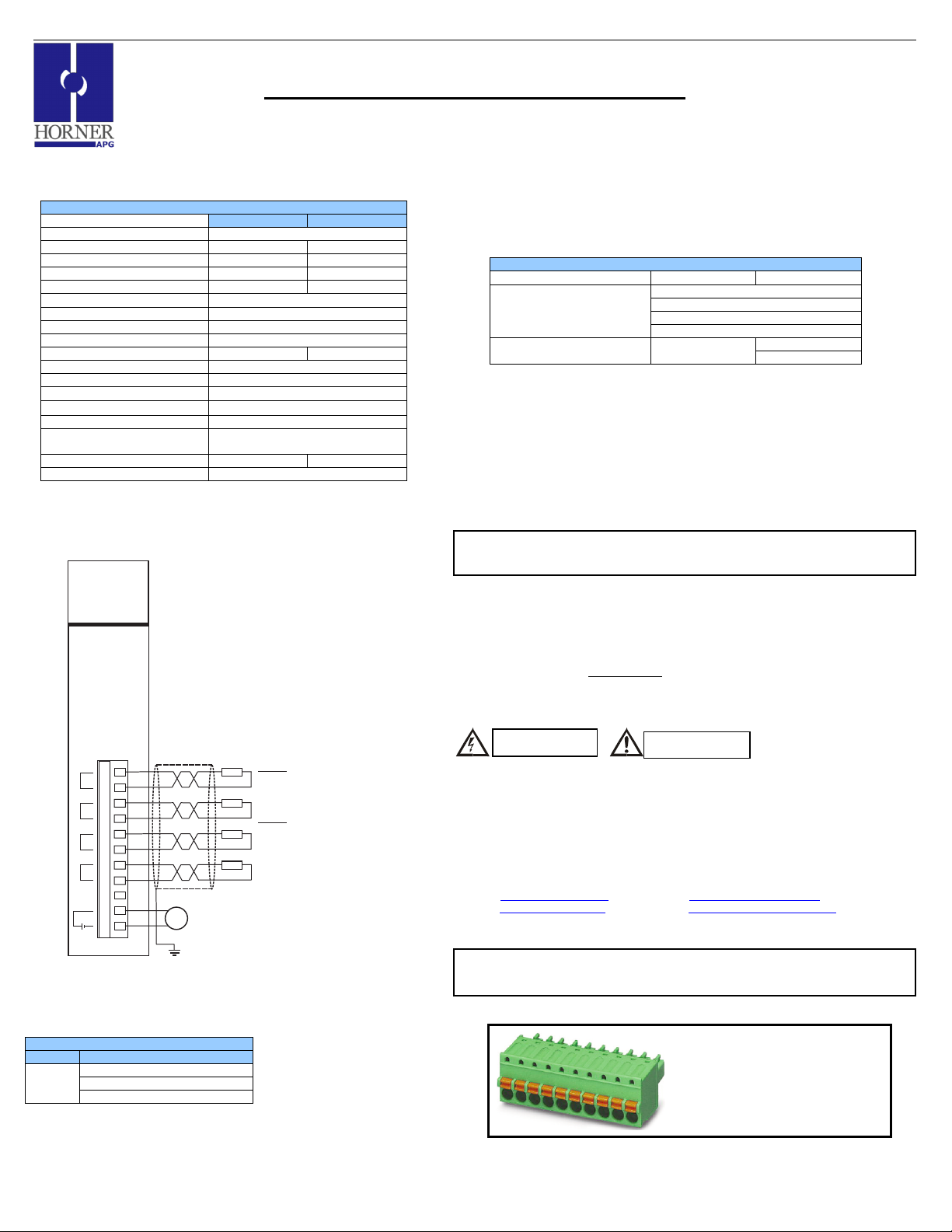
Prefer Spring-clamps?
Optional Spring-clamp style plugs are
available as economical wiring accessories.
See specification table for part number(s).
Representative 10-position plug shown.
 Loading...