

Page 1
MAN0951-02 12 May 2011 PAGE 1
HE-579ACM300
Information is subject to change without notice.
The SmartBlock ACM300 is a Power and Energy Monitor that is easy to setup, and provides a variety of
advanced features, including:
• 3-phase Power Monitoring with three
current (0-5A CTs) and voltage inputs
(480V, direct connect or PTs).
• CsCAN CAN network connection
provides a fast flexible communication
path.
• SmartBlock package allows convenient
mounting close to the source to be
monitored
• On board relay allows load shedding,
alarming or other local switching.
1 SPECIFICATIONS
CURRENT INPUTS
VOLTAGE INPUTS
Conversion
True RMS
78.1K samples/sec
Conversion
True RMS
CT Input
5A Secondary
PT Input (or direct)
480V Secondary
Burden
0.2VA
Burden
2.0Mohm
Range
1 to 150% of CT Primary
Input Range
40 to 600Vac
Full Scale
150% of CT Primary
Full Scale
600Vac
Accuracy
<1% of Full Scale
Accuracy
Better than 1% full scale
RELAY OUTPUT (Form C)
Current
1A max at 30Vdc
0.5A max at 125Vac
Contact Voltage
30Vdc, Max
125Vac, Max
MEASURED DATA VALUES
Phase A RMS voltage (Va)
Watts (W)
Phase B RMS voltage (Vb)
Power Factor (PF)
Phase C RMS voltage (Vc)
Volt-Amps (VA)
Phase A RMS current (Ia)
Volt-Amps Reactive (VAR)
Phase B RMS current (Ib)
Kilowatt Hour (KWhr)
Phase C RMS current (Ic)
Voltage Peak (Vpeak)
Frequency (Hz)
Current Peak (Ipeak)
GENERAL SPECIFICATIONS
Required Power (Steady State)
40mA @ 24VDC
Required Power
(Inrush)
14A for 50uSec
Primary Power Range
10-30VDC
Operating Temperature
0 to +60 C
Relative Humidity
5 to 95%, Non-condensing
Measurement Rating
CAT III Max 600V
CONNECTIVITY
CAN Port
Horner CsCAN Peer-to-Peer
SmartBlock Power and Energy Monitor
HE-579ACM300
Page 2
PAGE 2 12 May 2011 MAN0951-02
HE-559ACM300
Information is subject to change without notice.
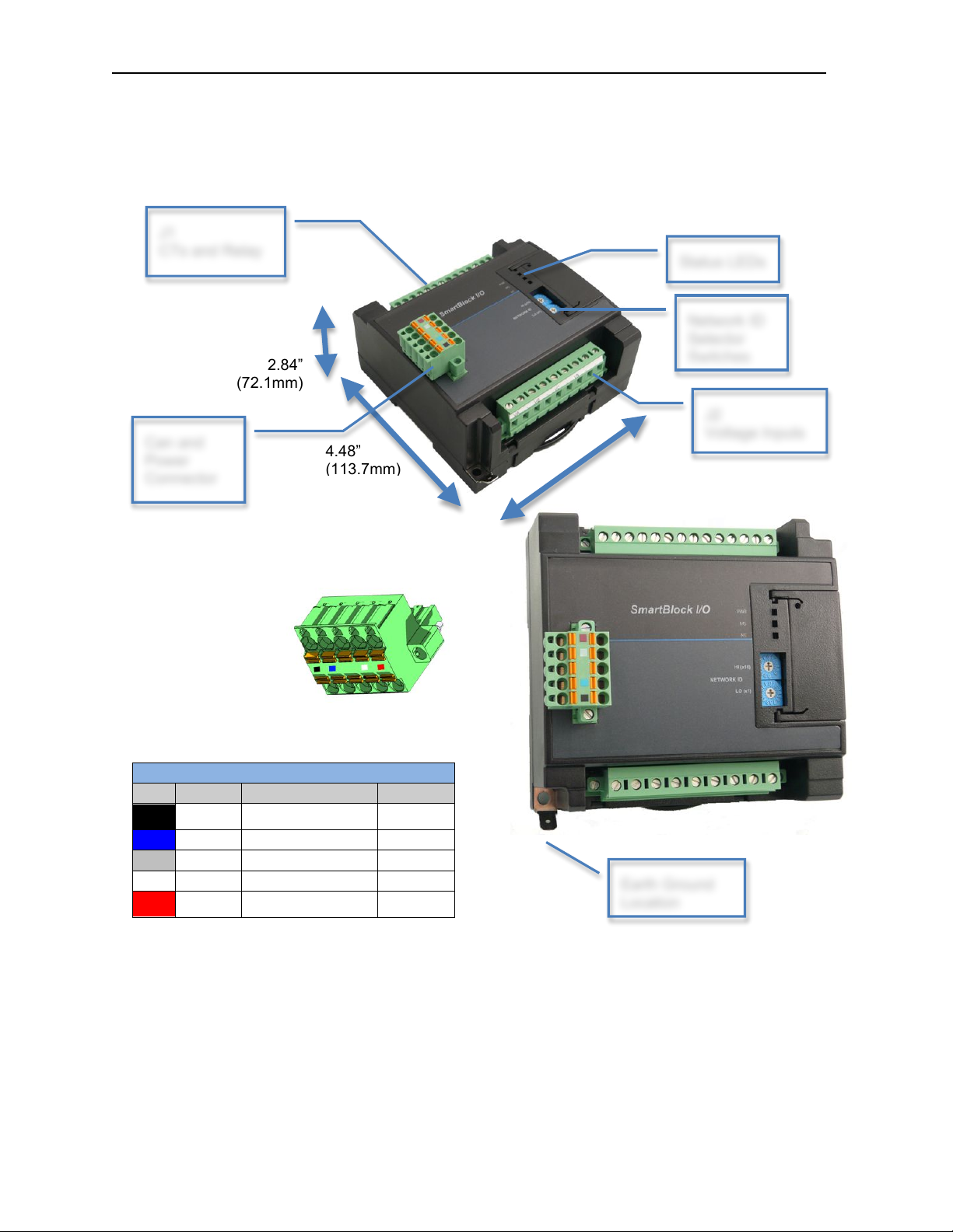
2 DIMENSIONS AND INSTALLATION
Network, Power and Grounding:
A single 5 pin connector is used to make both a network connection and power input. A quality class 2
power supply should be used for this product. If the power is run with the network cable, care must be
taken such that the voltage does not drop below the lower supply limit on longer runs.
A quality protective earth ground is required for safe and proper operation. The best protective earth
ground is achieved by screwing the lower left grounding location into a grounded back plate. Alternately
a protective earth ground can be connected to the spade lug.
Please see Horner manual MAN0799 for details on CAN wiring.
CAN Network & Power Port Pin Assignments
Pin
Signal
Signal Description
Direction
1
V-
CAN and Device
Ground - Black
!
2
CN_L
CAN Data Low - Blue
In/Out
3
SHLD
Shield Ground - None
!
4
CN_H
CAN Data High - White
In/Out
5
V+
Positive DC Voltage
Input (10-30VDC) - Red
!
4.56”
(115.8mm)
4.48”
(113.7mm)
2.16”
(54.8mm)
With connector
2.84”
(72.1mm)
CAN Network & Power
Connector
Torque rating 4.5 – 7 Lb-In
(0.50 – 0.78 N-m)
J1
CTs and Relay
J2
Voltage Inputs
Can and
Power
Connector
Network ID
Selector
Status LEDs
Earth Ground
Location
Page 3
MAN0951-02 12 May 2011 PAGE 3
HE-579ACM300
Information is subject to change without notice.
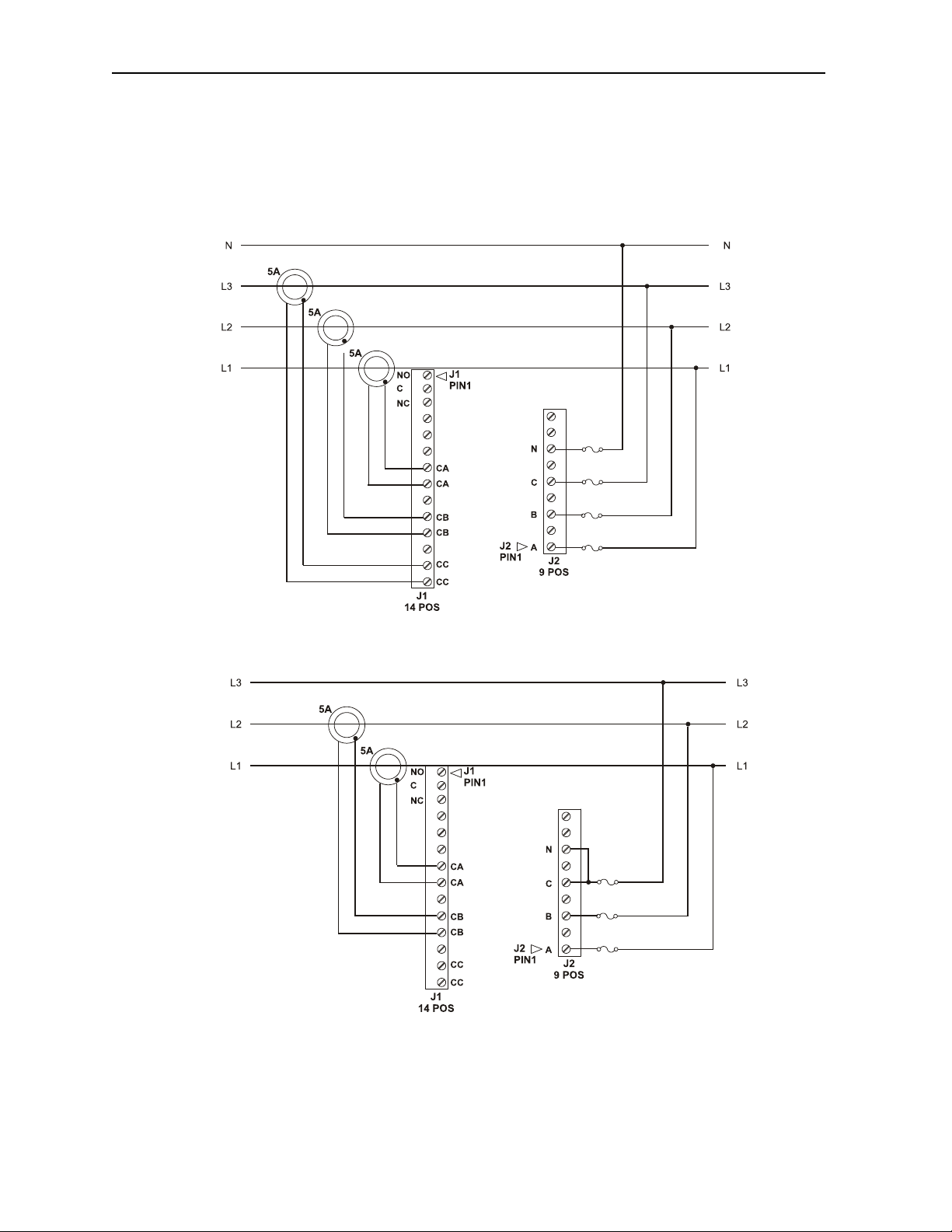
3 WIRING
4-wire Wye or 4-wire Delta
3-wire Delta
Page 4

PAGE 4 12 May 2011 MAN0951-02
HE-559ACM300
Information is subject to change without notice.
4 NETWORK DATA
Consumed Digital Data – This data is sent from the controller to the SmartBlock. For typical
applications the I/O configuration setup in Cscape will automatically populate this data. For more
advanced applications you may use NetPut functions to write this data. Please see the advanced
programming guide MAN0880 for more details.
Bit
Description
1
Q1 default
2
Q1 override
Upon module stop / timeout, if Q1 override is true, Q1 is set to Q1 default, otherwise the Q1
value is held. This override / hold polarity is consistent with OCS / Cscape usage but the
reverse of the legacy analog hold / override polarity in word 5.
3
Frequency Source, Set for phase B, Clear for phase A or C
4
Frequency Source, Set for phase C, Clear for phase A or B
If Clear
Always accumulate Watt-Hours
5
If Set
Do not accumulate Watt-Hours if load is under 0.005% of full scale to avoid meter
creep due to slight zero errors
6
Set to report period instead of frequency in AI13 / AI14
17
Relay output, set to ON to close N.O. and open N.C contacts.
23
Set to ON to clear KWhr, set to OFF to re-enable KWhr accumulator
24
Set to ON to clear Status flags, set to OFF to re-enable Status flags
Produced Digital Data – This data is sent from the SmartBlock to the controller. Normally this data is
mapped into specific registers in the I/O configuration in Cscape. For advanced applications NetGet
functions can be used to obtain this data. Since this data is broadcast to all controllers on the network
additional controllers can use NetGet functions to obtain this data as well.
Bit
Name
Description
I1
AEHF
Watt-Hour accumulator half full.
I2
REHF
VAR-Hour accumulator half full
I3
VAEHF
VA-Hour accumulator half
I4
SAGA
Voltage sag on Phase A
I5
SAGB
Voltage sag on Phase B
I6
SAGC
Voltage sag on Phase C
I7
ZXTOA
Zero Cross timeout on Phase A
I8
ZXTOB
Zero Cross timeout on Phase B
I9
ZXTOC
Zero Cross timeout on Phase C
I10
ZXA
Zero Cross detected on Phase A
I11
ZXB
Zero Cross detected on Phase B
I12
ZXC
Zero Cross detected on Phase C
I13
LENERGY
Reserved
I14
RESET
5V supply rail under 4 volts
I15
PKV
Peak voltage level exceeded
I16
PKI
Peak current level exceeded
I17
WFSM
Reserved
I18
REVPAP
Sign changed occurred in Watt calculation
I19
REVPRP
Sign changed occurred in VAR calculation
I20
SEQERR
A-B-C Rotation
Page 5

MAN0951-02 12 May 2011 PAGE 5
HE-579ACM300
Information is subject to change without notice.
Consumed Analog Data – This data is sent from the controller to the SmartBlock. For typical
applications the I/O configuration setup in Cscape will automatically populate this data. For more
advanced applications you may use NetPut functions to write this data. Please see the advanced
programming guide MAN0880 for more details.
Word
Description
Details
Word 1 / 2
REAL
PT A Ratio
Word 3 / 4
REAL
PT B Ratio
Word 5 / 6
REAL
PT C Ratio
Voltage Input Ratio
For example 120 to 480 step up enter 0.25
for 7200 to 480 step down enter 15
Word 7 / 8
REAL
CT A Ratio
Word 9 / 10
REAL
CT B Ratio
Word 11 / 12
REAL
CT C Ratio
Current Input Ratio
For example for 5A:100A CT enter 20
Word 13 / 14
REAL
CT A Phase Shift
Word 15 / 16
REAL
CT B Phase Shift
Word 17 / 18
REAL
CT C Phase Shift
Phase correction for CTs Enter in degrees
Min of -1.63° Lag, Max of +3.32 Lead
Word 19 / 20
REAL
Zero Cross Timeout
Seconds for zero cross alarm – max 2.5
Word 21 / 22
REAL
RMS Sag Voltage Level
Voltage Sag level in volts
Word 23
UINT
Sag Half Cycles
Number of half cycles before alarm
Word 24
UINT
Peak Level Half Cycles
Number of half cycles before alarm
Word 25 / 26
REAL
Voltage Peak Level
Voltage level for peak alarm
Word 27 / 28
REAL
Current Peak Level
Current level for peak alarm
Produced Analog Data – This data is sent from the SmartBlock to the controller. Normally this data is
mapped into specific registers in the I/O configuration in Cscape. For advanced applications NetGet
functions can be used to obtain this data. Since this data is broadcast to all controllers on the network
additional controllers can use NetGet functions to obtain this data as well.
Word
Function
Word 1 / 2
REAL
Phase A RMS Voltage
Word 3 / 4
REAL
Phase B RMS Voltage
Word 5 / 6
REAL
Phase C RMS Voltage
Word 7 / 8
REAL
Phase A RMS Current
Word 9 / 10
REAL
Phase B RMS Current
Word 11 / 12
REAL
Phase C RMS Current
Word 13 / 14
REAL
Frequency
Word 15 / 16
REAL
Watts
Word 17 / 18
REAL
PF Power Factor
Word 19 / 20
REAL
VA Volt-Amps
Word 21 / 22
REAL
VAR Volt-Amps Reactive
Word 23 / 24
REAL
KWhr
Word 25 / 26
REAL
Voltage Peak
Word 27 / 28
REAL
Current Peak
Page 6

PAGE 6 12 May 2011 MAN0951-02
HE-559ACM300
Information is subject to change without notice.
5 INSTALLATION / SAFETY
Warning: Remove power from the SmartBlock, CAN port, and any peripheral equipment
connected to this local system before adding or replacing this or any module.
Use the following wire type or equivalent:
• Belden 8917
• 16 AWG or larger
When found on the product, the following symbols specify:
WARNING: This unit should be located so that it is not accessible without the use of a tool.
WARNING: If this device is used in a way not specified by the manufacturer the safety provided
may be impaired.
WARNING: To avoid the risk of electric shock or burns, always connect the safety (or earth)
ground before making any other connections.
WARNING: To reduce the risk of fire, electrical shock, or physical injury it is strongly
recommended to fuse the voltage measurement inputs. Be sure to locate fuses as close to the
source as possible.
WARNING: Replace fuse with the same type and rating to provide protection against risk of fire
and shock hazards.
WARNING: In the event of repeated failure, do not replace the fuse again as a repeated failure
indicates a defective condition that will not clear by replacing the fuse.
WARNING: Only qualified electrical personnel familiar with the construction and operation of
this equipment and the hazards involved should install, adjust, operate, or service this
equipment. Read and understand this manual and other applicable manuals in their entirety
before proceeding. Failure to observe this precaution could result in severe bodily injury or loss
of life.
Warning: Consult user documentation.
Warning: Electrical Shock Hazard.
Note: Protective Earth Ground. Must be
connected to the system protective earth
ground for proper and safe operation
Page 7

MAN0951-02 12 May 2011 PAGE 7
HE-579ACM300
Information is subject to change without notice.
6 TECHNICAL SUPPORT
For assistance and manual up-dates, contact Technical Support at the following locations:
North America:
(317) 916-4274
www.heapg.com
Europe:
(+) 353-21-4321-266
www.horner-apg.com
 Loading...