

Page 1
MAN0561-02 27 FEB 2007 PAGE 1
x
Analog I/O Module
HE559MIX977
8 Input Channels
4 Sourcing Output Channels
±5V / ±10V / 4-20mA / ±20mA
CsCAN
SmartSti
Refer to SmartStix Analog Programming Guide (MAN0703) at www.HornerOCS.com
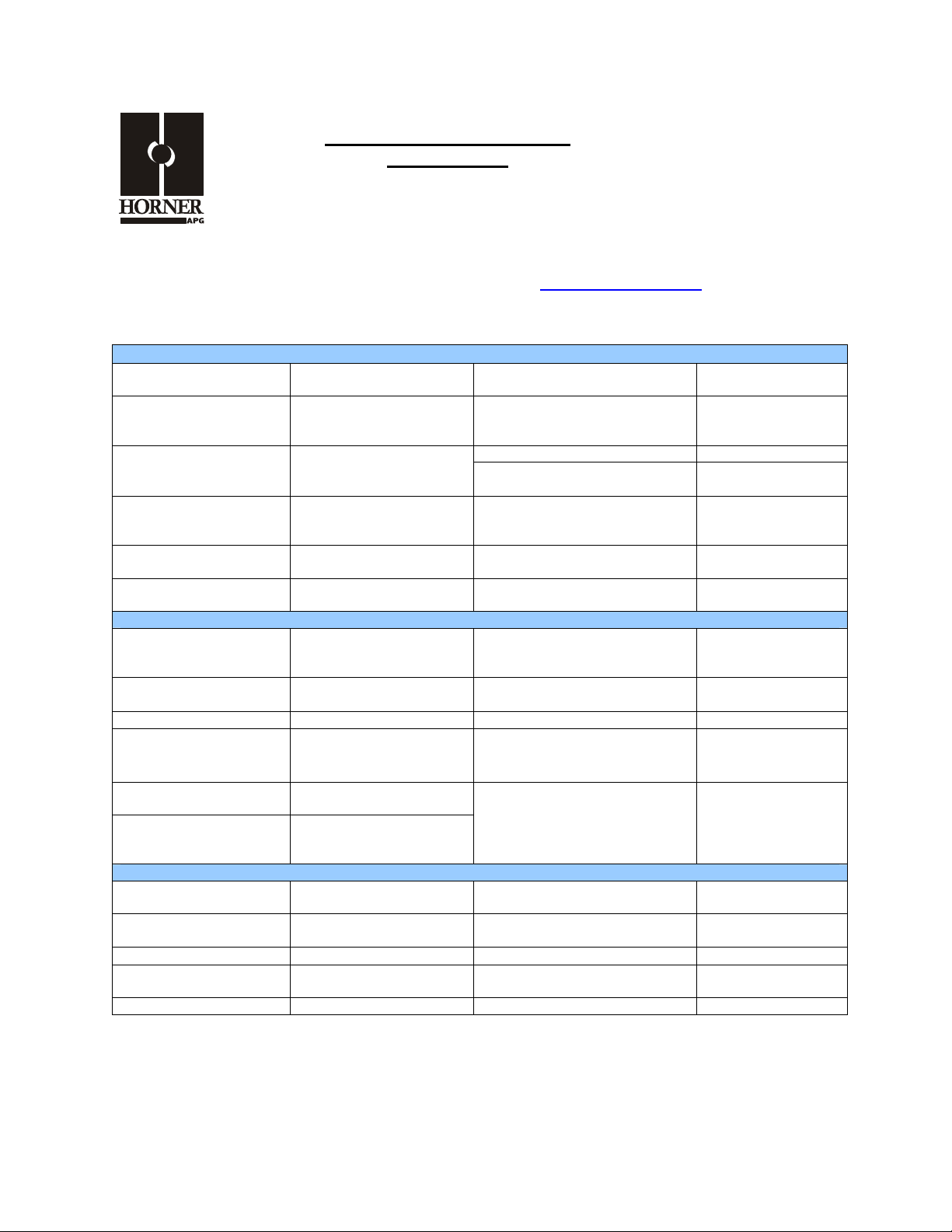
1 SPECIFICATIONS
ANALOG IN
Number of input points
Input Ranges
Resolution
Accuracy, 25°C
Input Impedance
Register Value for
Nominal Full Scale
Number of output
points
Output Ranges
Resolution
8
±5V, ±10V DC
4-20mA, ±20mA DC
14 bits
0.1%
V: 1 Megohm
mA: 150 Ohms
±32000
ANALOG OUT
4
±5, ±10V DC
4-20mA, ±20mA DC
14 bits
Conversion Time
Isolation
Isolation Method
Additional error for
temperatures other than 25°C
Maximum Continuous
Overload
Programmable Filter Time
Constants
Filter Modes
Isolation
Isolation Method
Output Clamp
.
10ms for all
Channels
1000V DC
IEC61010-1 300V
RMS
Magnetic
0.01% / °C
±10V: 150VAC
±20mA: ±30mA,
Clamped at ±6V
0.01 to 1.28 Seconds
Running Average or
Adaptive
1000V DC
IEC61010-1 300V
RMS
Magnetic
±12V, 600Wpk
Accuracy, 25°C
Load Resistance
Max Output current, mA
mode
Required Power
(Steady State)
Required Power
(Inrush)
Storage Temperature
Atmosphere
Cooling method
Free from corrosive gases
All information subject to change without notice.
0.1%
V: 600 Min
mA: 500 Max
3 channels driving 20mA
max output loads
GENERAL
3.6W
(150ma @ 24VDC)
8A @ 24VDC for 1ms
-25° to 70° C
and excessive dust
Self-cooling
Register Value for Nominal
Full Scale
Output Characteristic
Operating Temperature
Operating and Storage
Humidity
Altitude for use
Pollution degree
Weight
±32000
Sourcing
0° to 55° C
5 to 95% Non-
condensing
Up to 2,000m
2 or lower
9 oz. (256g)
Page 2
PAGE 2 27 FEB 2007 MAN0561-02
Vibration
Occasional Vibration
Frequency Acceleration Amplitude
10 ≤ f < 57 Hz
57 ≤ f ≤ 150
Hz
Frequency Acceleration Amplitude
10 ≤ f <
57 Hz
57≤ f ≤
150 Hz
Maximum shock acceleration
- 0.075 mm
9.8 m/s2 {1G} -
Continuous Vibration
- 0.035 mm
2
4.9 m/s
{0.5G}
-
Shocks
147 m/s
10 times in each direction for X,Y,Z
10 times in each direction for X,Y,Z
2
{15G}
Sweep
Count
Sweep
Count
Duration Time
Pulse Wave
Square wave impulse noise
Electrostatic Discharge
Radiated electromagnetic
field
Fast Transient
Burst Noise
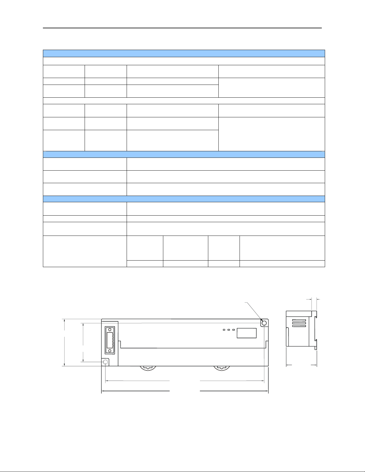
2 DIMENSIONS
1.97 [49.9mm]
1.62 [41.1mm]
Severity
level
Voltage
11 ms.
Half sine wave pulse (3 times in each of X, Y, Z directions)
Noise Immunity
AC: ± 1,500VDC
DC: ± 900VDC
Voltage: 4kV (contact discharge)
27 – 500MHz, 10V/m
All power
modules
2 kV 1 kV 0.25 kV
6.61 [167.9mm]
6.95 [176.5mm]
Digital
I/Os
(Ue ≥24V)
0.18 [4.6mm]
Digital I/Os
(Ue < 24 V)
Analog I/Os
Communication I/Os
0.31
[7.9mm]
[47.5mm]
HExx9-With
Removable
Terminal
1.87
Page 3
MAN0561-02 27 FEB 2007 Page 3
3 WIRING
FG
+/- 10V
+/- 10V
+/- 10V
FT
NC
NC
I2v
I2i
I4v
+/- 10V
I4i
+/-
20mA
+/-
20mA
+/-
20mA
+/-
20mA
+/- 10V
LOAD
+/- 10V
LOAD
+/- 20mA
LOAD
+/- 20mA
LOAD
C
I6v
I6i
I8v
I8i
C
Q2v
Q2i
Q4v
Q4i
C
24+
24C
FT
NC
I1v
I1i
I3v
I3i
I5v
I5i
I7v
I7i
Q1v
Q1i
Q3v
Q3i
C
C
C
*
**
Mix977
2 FG
4 FT
6 NC
8 NC
10 I2v
12 I2i
14 I4v
16 I4i
18 C
20 I6v
22 I6i
24 I8v
26 I8i
28 C
30 Q2v
32 Q2i
34 Q4v
36 Q4i
38 C
FT: Factory Test, Do Not Connect
Mix977
1 24+ *
3 24C **
5 FT
7 NC
9 I1v
11 I1i
13 C
15 I3v
17 I3i
19 I5v
21 I5i
23 C
25 I7v
27 I7i
29 Q1v
31 Q1i
33 C
35 Q3v
37 Q3i
006MIX002
C terminals are connected together internally but isolated from bus and power ci rcuits.
* and ** For CsCAN and DeviceNet versions, module power is usually derived from the CAN con ne ctor.
In that case, +24VDC and 24C are not
connected.
All information subject to change without notice.
Page 4

PAGE 4 27 FEB 2007 MAN0561-02
Ω
_
4 INTERNAL WIRING
I/O Connector
Voltage
Input
SmartStack Inputs
700K
Field
Side
+
To
Controller
Current
Input
300K
Ω
150Ω
Isolated
Common
6V
I/O Connector
Voltage
Output
Field
Side
Current
Output
Isolated
Common
100Ω
SmartStack Outputs
Mode
-
+
Ω
100
Mode
<
From
Controller
Page 5

MAN0561-02 27 FEB 2007 Page 5
5 Channel Mode, Programmable Filter, and Output Default Configuration
The network supplies configuration information to the HE550MIX977 in the Consumed Directed Digital
Data Words sent to the HE550MIX977. In the first word, the low 12 bits, 1 through 12, are channel mode
bits. A low mode bit selects ±10V and a high mode bit selects ±20mA. The next three bits, 13 through
15, are input digital filter time constant codes and the high bit, 16, is an adaptive filter enable bit. In the
second word, the low 12 bits are channel scale bits. A low scale bit selects ±10V or ±20mA for the
corresponding channel. A high scale bit selects ±5V or 4-20mA. The upper four bits are unused.
Bit Channel
1 AI1
2 AI2
3 AI3
4 AI4
5 AI5
6 AI6
7 AI7
8 AI8
9 AQ1
10 AQ2
11 AQ3
12 AQ4
Each analog input on the HE550MIX977 has a single pole 345Hz (461uS) cutoff high frequency noise
filter. In addition a second digital filter may be specified in the first configuration word with the following
time constants.
Bit Time Constant
15 14 13
0 0 0 10 milliseconds (Nominal hardware scan rate)
0 0 1 15 milliseconds
0 1 0 35 milliseconds
0 1 1 75 milliseconds
1 0 0 155 milliseconds
1 0 1 315 milliseconds
1 1 0 635 milliseconds
1 1 1 1.275 seconds
This digital filter is useful for applications with significant amounts of random noise. The slower time
constants, while yielding better noise suppression, take a longer time to settle after step changes and are
also sensitive to impulse noise which is treated like Gaussian noise and averaged.
Bit 16 of the first configuration word may be set to specify an adaptive filter algorithm that:
1. Responds much more quickly to large step changes at slower time constants with full filtering of low
level noise.
2. Suppresses impulse noise at the expense of slightly slower response at the shortest time constant
settings. (Approximately 10 additional milliseconds)
Note that actual system response time is network dependent.
All information subject to change without notice.
Page 6

PAGE 6 27 FEB 2007 MAN0561-02
Bits 9 through 12 of the 5th configuration word control the behavior of the analog outputs when network
communication is lost. The bit to channel correspondence is the same as for the mode and scale bits. If
the corresponding bit is set, the outputs hold the last state. If the corresponding bit is cleared, the outputs
are set to the respective value supplied to the HE550MIX977 in the second four words of the Consumed
Directed Analog Data sent by the OCS. The other bits of the 5th configuration word are unused.
Refer to SmartStix Analog Programming Guide.
6 INPUT and OUTPut conversion factorS
The following table describes how real-world values are scaled in the controller. For a given physical
voltage or current, the register data value may be calculated by using the conversion factor from the
table. The following formula is used: Data = Voltage or Current / Conversion Factor
Example: The user selects a voltage range of ±10V:
1. The physical voltage is 6 Volts.
2. Using the table, the conversion factor for the voltage range of ±10V is .0003125.
3. To determine the data value, the formula is used: Data = V / Conversion Factor
19200 = 6 VDC / 0.0003125
Conversion between Physical Values and Register Values
Selected Range Volts / mA Register Data Conversion Factor
> 5.11 32767
5.00 32000
±5.00 V
0.00 0
0.00015625
-5.00 -32000
< -5.11 -32768
> 10.23 32767
10.00 32000
±10.00 V
0.00 0
0.0003125
-10.00 -32000
< -10.23 -32768
< 20.37 32767
20.00 32000
* 4 to 20 mA
4.00 0
0.0005
-12.00 -32000
> -12.38 -32768
> 20.47 32767
20.00 32000
±20.00 mA
0 0
0.0006250
-20.00 -32000
< -20.47 -32768
* For the 4 to 20mA range, the offset, 4mA, must first be subtracted from the physical output value
before dividing by the scale factor to yield the register data value.
Page 7

MAN0561-02 27 FEB 2007 Page 7
7 SETTING ID SWITCHES
CsCAN Network IDs are set using the hexadecimal number system from 01 to FD. The decimal
equivalent is 1-253. Refer to following Conversion Table, which shows the decimal equivalent of
hexadecimal numbers. Set a unique Network ID by inserting a small Phillips screwdriver into the two
identical switches.
Note: The CsCAN Baud Rate for SmartStix I/O is fixed at 125KBaud
Power and Diagnostic
LEDs
Use this switch to set the
High Digit –has an x16
multiplier.
Use this switch to set
the Low Digit – has an
x1 multiplier.
SmartStix I/O
MS NSPWR
LO (x1) HI (x16)
Close-up of Switches
All information subject to change without notice.
Page 8

PAGE 8 27 FEB 2007 MAN0561-02
Decimal (Dec) to Hexadecimal (Hex) Conversion
Dec Hex Dec Hex Dec Hex Dec Dec Hex
HI LO HI LO HI LO HI LO HI LO
54 3 6 108 6 C
1 0 1 55 3 7 109 6 D
2 0 2 56 3 8 110 6 E
3 0 3 57 3 9 111 6 F
4 0 4 58 3 A 112 7 0
5 0 5 59 3 B 113 7 1
6 0 6 60 3 C 114 7 2
7 0 7 61 3 D 115 7 3
8 0 8 62 3 E 116 7 4
9 0 9 63 3 F 117 7 5
10 0 A 64 4 0 118 7 6
11 0 B 65 4 1 119 7 7
12 0 C 66 4 2 120 7 8
13 0 D 67 4 3 121 7 9
14 0 E 68 4 4 122 7 A
15 0 F 69 4 5 123 7 B
16 1 0 70 4 6 124 7 C
17 1 1 71 4 7 125 7 D
18 1 2 72 4 8 126 7 E
19 1 3 73 4 9 127 7 F
20 1 4 74 4 A 128 8 0
21 1 5 75 4 B 129 8 1
22 1 6 76 4 C 130 8 2
23 1 7 77 4 D 131 8 3
24 1 8 78 4 E 132 8 4
25 1 9 79 4 F 133 8 5
26 1 A 80 5 0 134 8 6
27 1 B 81 5 1 135 8 7
28 1 C 82 5 2 136 8 8
29 1 D 83 5 3 137 8 9
30 1 E 84 5 4 138 8 A
31 1 F 85 5 5 139 8 B
32 2 0 86 5 6 140 8 C
33 2 1 87 5 7 141 8 D
34 2 2 88 5 8 142 8 E
35 2 3 89 5 9 143 8 F
36 2 4 90 5 A 144 9 0
37 2 5 91 5 B 145 9 1
38 2 6 92 5 C 146 9 2
39 2 7 93 5 D 147 9 3
40 2 8 94 5 E 148 9 4
41 2 9 95 5 F 149 9 5
42 2 A 96 6 0 150 9 6
43 2 B 97 6 1 151 9 7
44 2 C 98 6 2 152 9 8
45 2 D 99 6 3 153 9 9
46 2 E 100 6 4 154 9 A
47 2 F 101 6 5 155 9 B
48 3 0 102 6 6 156 9 C
49 3 1 103 6 7 157 9 D
50 3 2 104 6 8 158 9 E
51 3 3 105 6 9 159 9 F
52 3 4 106 6 A 160 A 0
53 3 5 107 6 B 161 A 1
162
163
164
165
166
167
168
169
170
171
172
173
174
175
176
177
178
179
180
181
182
183
184
185
186
187
188
189
190
191
192
193
194
195
196
197
198
199
200
201
202
203
204
205
206
207
208
209
210
211
212
213
214
215
A 2
A 3
A 4
A 5
A 6
A 7
A 8
A 9
A A
A B
A C
A D
A E
A F
B 0
B 1
B 2
B 3
B 4
B 5
B 6
B 7
B 8
B 9
B A
B B
B C
B D
B E
B F
C 0
C 1
C 2
C 3
C 4
C 5
C 6
C 7
C 8
C 9
C A
C B
C C
C D
C E
C F
D 0
D 1
D 2
D 3
D 4
D 5
D 6
D 7
216
217
218
219
220
221
222
223
224
225
226
227
228
229
230
231
232
233
234
235
236
237
238
239
240
241
242
243
244
245
246
247
248
249
250
251
252
253
D 8
D 9
D A
D B
D C
D D
D E
D F
E 0
E 1
E 2
E 3
E 4
E 5
E 6
E 7
E 8
E 9
E A
E B
E C
E D
E E
E F
F 0
F 1
F 2
F 3
F 4
F 5
F 6
F 7
F 8
F 9
F A
F B
F C
F D
Page 9

MAN0561-02 27 FEB 2007 Page 9
8 LEDS
SmartStix I/O Modules provide diagnostic and status LED indicators.
a. Diagnostic LED Indicators
Diagnostic LED State Meaning
Solid Red RAM or ROM test failed
MS
(indicates fault status of the Module )
Blinking Red I/O test failed
Blinking Green Module is in power-up state
Solid Green Module is running normally
Solid Red Network Ack or Dup ID test failed
NS
(indicates fault status of the Network)
Blinking Red Network ID test failed
Blinking Green Module is in Life Expectancy default state
Solid Green Network is running normally
b. Status LED Indicators
The Power Status LED illuminates Red when power is applied to the module. There are I/O Status LED
indicators for each of the Digital I/O points, which illuminate Red when an I/O point is ON.
9 NETWORK CABLE
For detailed wiring information, refer to Chapter Two in the Control Station Hardware Manual
(MAN0227). A handy checklist is provided that covers panel box layout requirements and minimum
clearances.
Pin Description
RED 1 V+
WHT 2 CAN_H
SHD 3 Shield
BLU 4 CAN_L
BLK 5 V-
Recommended Cable
Thick: (Max Distance = 500m) Belden 3082A
Thin: (Max Distance = 100m) Belden 3084A
CN_LV-SHIELD121
V+
CN_H
CN_LV-SHIELD
V+
CN_H
CN_LV-SHIELD
V+
CN_H
CN_LV-SHIELD
V+
CN_H
Ω
BLU
BLK
RED
RED
WHT
-
+
12-25VDC
BLK
BLK
BLU
BLU
WHT
WHT
SHIELD
RED
RED
SHIELD
BLK
BLK
BLU
BLU
WHT
WHT
RED
RED
SHIELD
BLK
Ω
121
BLU
001CAN002
WHT
RED
CAN Wiring
Note: 12 - 24VDC must be supplied to the network.
All information subject to change without notice.
Page 10

PAGE 10 27 FEB 2007 MAN0561-02
10 INSTALLATION / SAFETY
a. All applicable codes and standards need to be followed in the installation of this product.
b. For I/O wiring (discrete), use the following wire type or equivalent: Belden 8441 or equivalent.
c. For detailed installation information, refer to Chapter Two in the Control Station Hardware Manual
(MAN0227). A handy checklist
is provided that covers panel box layout requirements and
minimum clearances.
Warning: Consult user documentation.
Warning: Electrical Shock Hazard.
11 TECHNICAL ASSISTANCE
For assistance, contact Technical Support at the following locations:
North America:
(317) 916-4274
www.heapg.com
Europe:
(+) 353-21-4321-266
www.horner-apg.com
 Loading...