

Page 1
MAN0896-01 Specifications / Installation
HE559-With Removable
6.95 [176.5mm]
Use this switch to set
Use this switch
to set the
Power and Diagnostic
LEDs
INPUT
3 9 12 13 14 15 16 10
3 9 12 13 14 15 16 10
1 GENERAL SPECIFICATIONS
Storage
Temperature
Operating
Temperature
Atmosphere
Vibration
Frequency Acceleration Amplitude
10 ≤ f < 57 Hz
57 ≤ f ≤ 150 Hz
Frequency Acceleration Amplitude
10 ≤ f <
57 Hz
57≤ f ≤
150 Hz
Shocks
Maximum shock
acceleration
Duration Time 11 ms.
Pulse Wave
Noise Immunity
Square wave impulse
noise
Electrostatic
Discharge
Radiated
electromagnetic field
Fast Transient
Burst Noise
16 DC Outputs (24VDC, positive logic, 0.5A) / 32 DC Outputs (24VDC, positive logic, 0.5A)
General Specifications
-25° to 70° C
0° to 55° C
Free from
corrosive gases
and excessive
dust
Occasional Vibration
- 0.075 mm
9.8 m/s2 {1G} -
Continuous Vibration
- 0.035 mm
4.9 m/s2 {0.5G} -
Severity
level
Voltage 2 kV 1 kV 0.25 kV
SmartStixTM HE559DQM606/HE559DQM706
Remote I/O for the OCS/RCS Family
Operating and
Storage
Humidity
Pollution
degree
Cooling
method
147 m/s2 {15G}
Half sine wave pulse (3 times in each of X, Y, Z
Voltage: 4kV (contact discharge)
All power
directions)
AC: ± 1,500VDC
DC: ± 900VDC
27 – 500MHz, 10V/m
modules
Digital
I/Os
(Ue ≥24V)
5 to 95% Non-
condensing
2 or lower
Self-cooling
Sweep
Count
10 times in
each direction
for X,Y,Z
Sweep
Count
10 times in
each direction
for X,Y,Z
Digital I/Os
(Ue < 24 V)
Analog I/Os
Communicatio
n I/Os
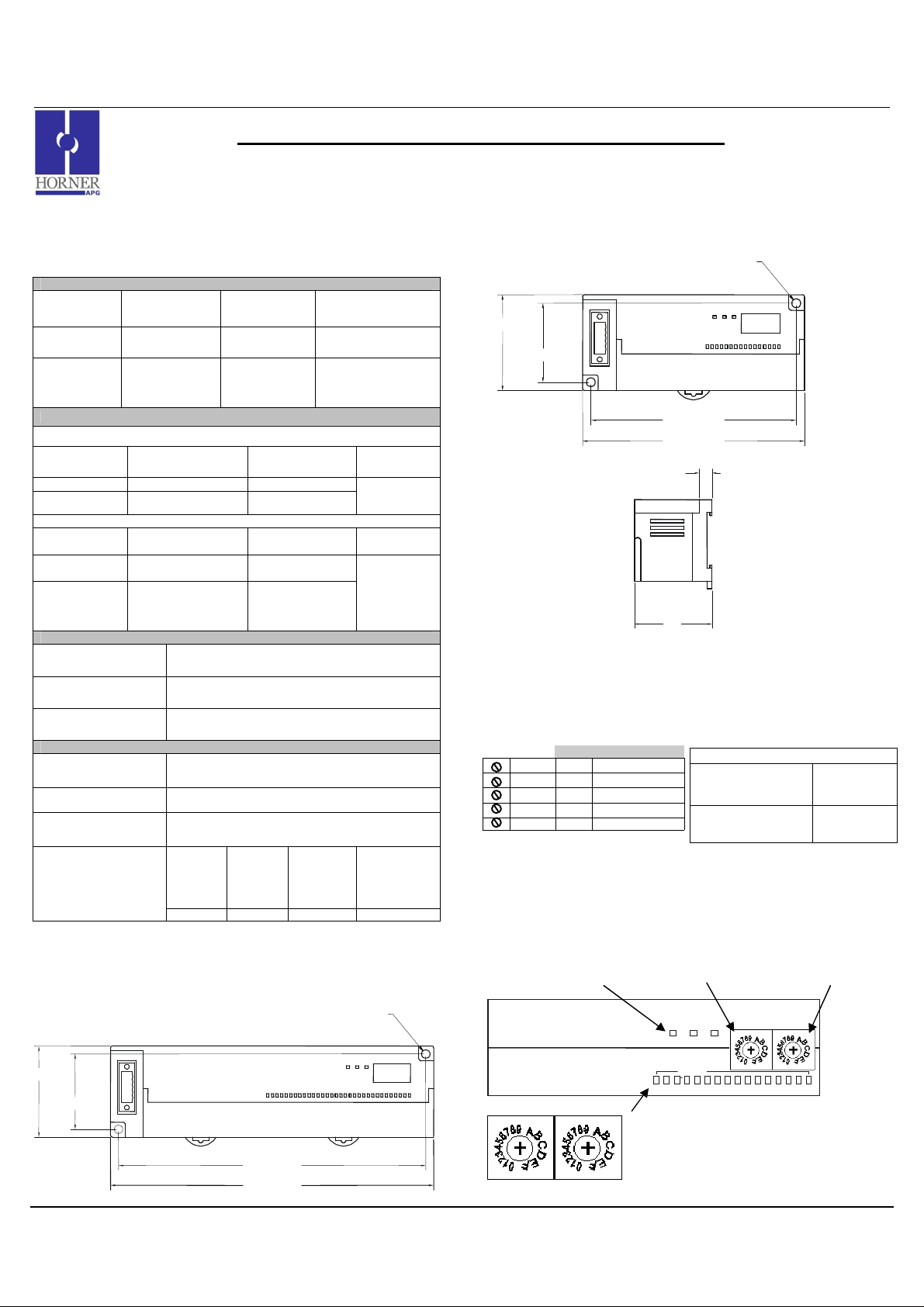
2 DIMENSIONS
a. DQM706
0.18 [4.6mm]
1.97 [49.9mm]
1.62 [41.1mm]
03/02/2009 Page 1 of 3 ECN # 952
6.61 [167.9mm]
b. DQM606
1.97 [49.9mm]
c. Terminal Strips
1.62 [41.1mm]
0.18 [4.6mm]
4.21 [106.9mm]
4.55 [115.6mm]
0.31
1.87
Strip
3 NETWORK CABLE
For detailed wiring information, refer to the Control Station Hardware Manual. A
handy checklist is provided that covers panel box layout requirements and minimum
clearances. See Section 10 for our web address.
Pin Description
RED 1 V+
WHT 2 CAN_H
NC 3 No Connection
BLU 4 CAN_L
BLK 5 V-
4 ID SWITCHES (SETTING CSCAN NETWORK IDs)
CsCAN Network IDs are set using the hexadecimal number system from 01 to FD. The
decimal equivalent is 1-253. Refer to Section 8, which shows the decimal equivalent of
hexadecimal numbers. Set a unique Network ID by inserting a small Phillips screwdriver
into the two identical switches. Note: The CsCAN Baud Rate for SmartStix I/O is fixed at
125KBaud
Recommended Cable
Thick:
(Max Distance =
500m)
Thin:
(Max Distance =
100m)
Belden 3082A
Belden 3084A
SmartStix I/O
SmartStix I/O
High Digit –has an x16
multiplier.
PWR
PWR
MS NS
MS NS
the Low Digit – has
an x1 multiplier.
HI (x16)
HI (x16)
LO (x1)
LO (x1)
I/O Status LEDs
INPUTS
2 1 4 5 6 7 8 11
2 1 4 5 6 7 8 11
Close-up of Switches
006DIM001
Page 2
MAN0896-01 Specifications / Installation
006DQM008
-
R2
Note:
If desired, C1 and C2 can
Field
From
5 LEDs
a. Diagnostic LED Indicators
Diagnostic LED State Meaning
MS: (indicates fault status of
Module )
NS: (indicates fault status of
Network)
b. Status LED Indicators
The Power Status LED illuminates Red when power is applied to the module. There are
I/O Status LED indicators for each of the Digital I/O points, which illuminate Red when an
I/O point is ON.
Solid Red RAM or ROM test failed
Blinking Red I/O test failed
Blinking Green Module is in power-up state
Solid Green Module is running normally
Solid Red Network Ack or Dup ID test failed
Blinking Red Network ID test failed
Blinking Green
Solid Green Network is running normally
Module is in Life Expectancy default
state
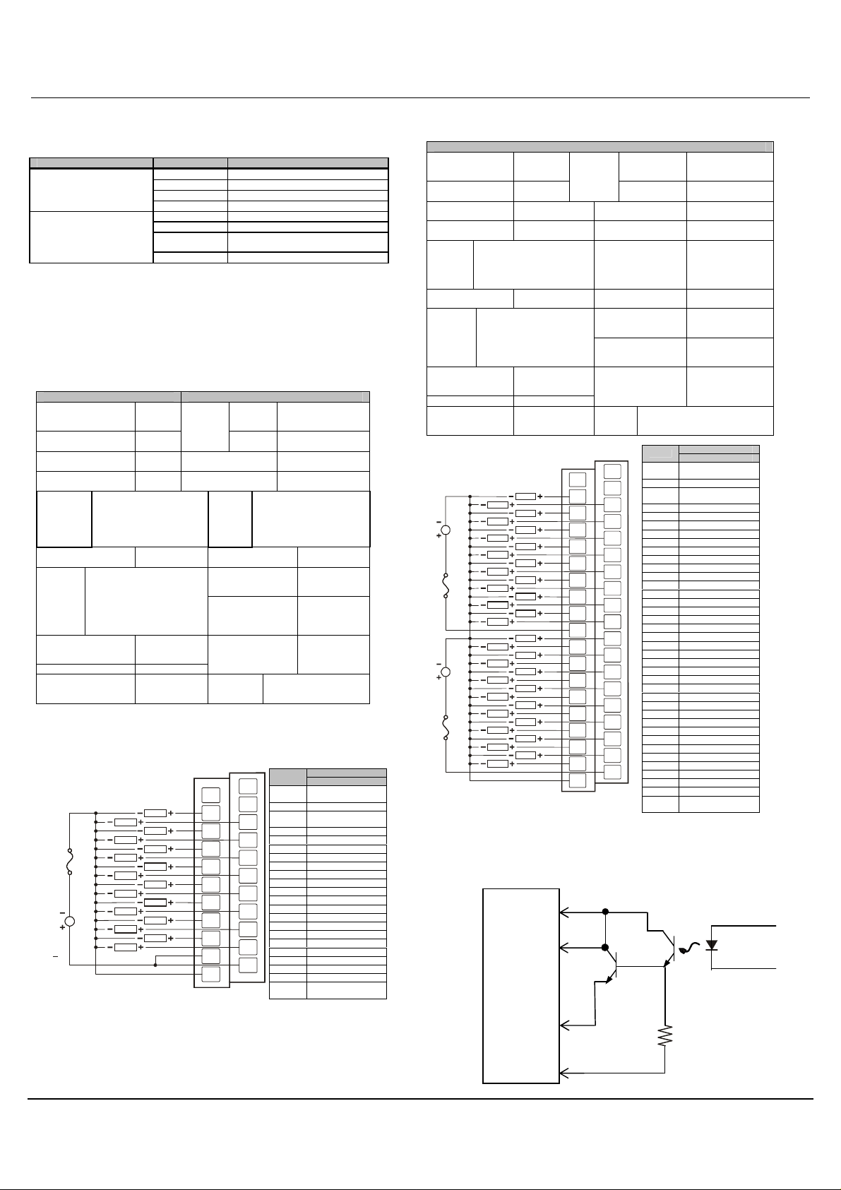
6 WIRING
a. 16 DC OUT, Positive Logic
DQM606 Outputs
Number of output
points
Commons per
Module
Operating Voltage
Rated Load Voltage
Max.
Load
Current
per
channel
OFF Leakage
Current
Max.
Inrush
Current
per
channel
Maximum Voltage
Drop during ON
circuit
Rated Voltage 11 – 25 VDC
Internal power
Consumption (mA)
0.5A Max. per output 3A
16 Voltage
1
24VDC
24VDC
per common
0.1mA or less Common Method
1A, 10ms
1.5VDC(0.5A)
280 Weight 6.7 oz. (191g)
External
Power
Supply
OFF to ON
Response
ON to OFF
Response
Current
Output
Type
Operating Indicator
External
connections
Isolation methods Photo Coupler
24VDC ± 10% (ripple
voltage: 4Vp-p or
less)
30mA (TYP, All
points ON)
2ms.
2ms.
Sourcing
16 points /
COM
LED turns on
during ON
state of output
Terminal block
connector
(M3 x 6
screws)
24VDC
LOAD
LOAD
LOAD
LOAD
LOAD
LOAD
LOAD
LOAD
LOAD
LOAD
LOAD
LOAD
LOAD
LOAD
LOAD
LOAD
FG
Q1
Q3
Q5
Q7
Q9
Q11
Q13
Q15
COM
0V
006DQM007-R1
Pin
NC
NC*
NC
FG Frame Ground
NC*
Q2
Q1 Output 1
Q2 Output 2
Q4
Q3 Output 3
Q4 Output 4
Q6
Q5 Output 5
Q6 Output 6
Q8
Q7 Output 7
Q10
Q12
Q14
Q16
COM
Q8 Output 8
Q9 Output 9
Q10 Output 10
Q11 Output 11
Q12 Output 12
Q13 Output 13
Q14 Output 14
Q15 Output 15
Q16 Output 16
COM Isolated Common
COM Isolated Common
0V
Signal
DQM606
No Connection
(*Do not Connect)
No Connection
(*Do not Connect)
Isolated Power
Negative
b. 32 DC OUT, Positive Logic
DQM706 Outputs
Number of output
points
Commons per
Module
Operating Voltage
Rated Load
Voltage
Max.
Load
Current
per
channel
OFF Leakage
Current
Max.
Inrush
Current
per
channel
Maximum Voltage
Drop during ON
circuit
Rated Voltage 11 – 25 VDC
Internal power
Consumption
(mA)
0.5A Max. per output 3A per
1A, 10ms
24VDC
24VDC
LOAD
LOAD
LOAD
LOAD
LOAD
LOAD
LOAD
LOAD
LOAD
LOAD
LOAD
LOAD
LOAD
LOAD
LOAD
LOAD
use a single supply.
7 INTERNAL WIRING
a. DQM606
I/O Connector
COM
Side
Q1
0V
32 Voltage
External
Power
Supply
2
24VDC
24VDC
common
0.1mA or less Common Method 16 points / COM
1.5VDC(0.5A)
380 Weight 10.22 (290g)
FG
LOAD
LOAD
LOAD
LOAD
LOAD
LOAD
LOAD
LOAD
LOAD
LOAD
LOAD
LOAD
LOAD
LOAD
LOAD
LOAD
Q16
Q1
Q3
Q5
Q7
Q9
Q11
Q13
Q15
C1
Q18
Q20
Q22
Q24
Q26
Q28
Q30
Q32
0V
Current
OFF to ON
Response
ON to OFF
Response
Output Type Sourcing
Operating Indicator LED turns on
External
connections
Isolation methods Photo Coupler
NC
NC
Q2
Q4
Q6
Q8
Q10
Q12
Q14
Q16
Q17
Q19
Q21
Q23
Q25
Q27
Q29
Q31
C2
24VDC ±
10%(ripple voltage:
4Vp-p or less)
30mA (TYP, All
points ON)
2ms.
2ms.
during ON state of
output
Terminal block
connector
(M3 x 6 screws)
Pin
NC*
FG* Frame Ground
NC*
Q1 Output 1
Q2 Output 2
Q3 Output 3
Q4 Output 4
Q5 Output 5
Q6 Output 6
Q7 Output 7
Q8 Output 8
Q9 Output 9
Q10 Output 10
Q11 Output 11
Q12 Output 12
Q13 Output 13
Q14 Output 14
Q15 Output 15
Q16 Output 16
C1 Isolated Common 1
Q17 Output 17
Q18 Output 18
Q19 Output 19
Q20 Output 20
Q21 Output 21
Q22 Output 22
Q23 Output 23
Q24 Output 24
Q25 Output 25
Q26 Output 26
Q27 Output 27
Q28 Output 28
Q29 Output 29
Q30 Output 30
Q31 Output 31
Q32 Output 32
C2 Isolated Common 2
0V
SmartStix
Signal
DQM706
No Connection
(*Do not Connect)
No Connection
(*Do not Connect)
Isolated Power
Negative
Controller
03/02/2009 Page 2 of 3 ECN # 952
Page 3

MAN0896-01 Specifications / Installation
Warning
: Connecting high voltage to any I/O pin may cause high voltage to
subject to change without notice.
Field
Q17 – Q32
From
From
Q1 – Q16
b. DQM706
I/O Connector
C1
SmartStix
Controller
Side
Typical
C2
Controller
Typical
0V
8 DECIMAL (DEC) TO HEXADECIMAL (HEX) CONVERSION TABLE
Dec Hex Dec Hex Dec Hex
HI LO HI LO HI LO
0 0 0 86 5 6
1 0 1 87 5 7 173 A D
2 0 2 88 5 8 174 A E
3 0 3 89 5 9 175 A F
4 0 4 90 5 A 176 B 0
5 0 5 91 5 B 177 B 1
6 0 6 92 5 C 178 B 2
7 0 7 93 5 D 179 B 3
8 0 8 94 5 E 180 B 4
9 0 9 95 5 F 181 B 5
10 0 A 96 6 0 182 B 6
11 0 B 97 6 1 183 B 7
12 0 C 98 6 2 184 B 8
13 0 D 99 6 3 185 B 9
14 0 E 100 6 4 186 B A
15 0 F 101 6 5 187 B B
16 1 0 102 6 6 188 B C
17 1 1 103 6 7 189 B D
18 1 2 104 6 8 190 B E
19 1 3 105 6 9 191 B F
20 1 4 106 6 A 192 C 0
21 1 5 107 6 B 193 C 1
22 1 6 108 6 C 194 C 2
23 1 7 109 6 D 195 C 3
24 1 8 110 6 E 196 C 4
25 1 9 111 6 F 197 C 5
26 1 A 112 7 0 198 C 6
27 1 B 113 7 1 199 C 7
28 1 C 114 7 2 200 C 8
29 1 D 115 7 3 201 C 9
30 1 E 116 7 4 202 C A
31 1 F 117 7 5 203 C B
32 2 0 118 7 6 204 C C
33 2 1 119 7 7 205 C D
34 2 2 120 7 8 206 C E
35 2 3 121 7 9 207 C F
36 2 4 122 7 A 208 D 0
172
A C
37 2 5 123 7 B 209 D 1
38 2 6 124 7 C 210 D 2
39 2 7 125 7 D 211 D 3
40 2 8 126 7 E 212 D 4
41 2 9 127 7 F 213 D 5
42 2 A 128 8 0 214 D 6
43 2 B 129 8 1 215 D 7
44 2 C 130 8 2 216 D 8
45 2 D 131 8 3 217 D 9
46 2 E 132 8 4 218 D A
47 2 F 133 8 5 219 D B
48 3 0 134 8 6 220 D C
49 3 1 135 8 7 221 D D
50 3 2 136 8 8 222 D E
51 3 3 137 8 9 223 D F
52 3 4 138 8 A 224 E 0
53 3 5 139 8 B 225 E 1
54 3 6 140 8 C 226 E 2
55 3 7 141 8 D 227 E 3
56 3 8 142 8 E 228 E 4
57 3 9 143 8 F 229 E 5
58 3 A 144 9 0 230 E 6
59 3 B 145 9 1 231 E 7
60 3 C 146 9 2 232 E 8
61 3 D 147 9 3 233 E 9
62 3 E 148 9 4 234 E A
63 3 F 149 9 5 235 E B
64 4 0 150 9 6 236 E C
65 4 1 151 9 7 237 E D
66 4 2 152 9 8 238 E E
67 4 3 153 9 9 239 E F
68 4 4 154 9 A 240 F 0
69 4 5 155 9 B 241 F 1
70 4 6 156 9 C 242 F 2
71 4 7 157 9 D 243 F 3
72 4 8 158 9 E 244 F 4
73 4 9 159 9 F 245 F 5
74 4 A 160 A 0 246 F 6
75 4 B 161 A 1 247 F 7
76 4 C 162 A 2 248 F 8
77 4 D 163 A 3 249 F 9
78 4 E 164 A 4 250 F A
79 4 F 165 A 5 251 F B
80 5 0 166 A 6 252 F C
81 5 1 167 A 7 253 F D
82 5 2 168 A 8 254 F E
83 5 3 169 A 9 255 F F
84 5 4 170 A A
85 5 5 171 A B
9 INSTALLATION / SAFETY
a. All applicable codes and standards need to be followed in the installation of
this product.
b. For I/O wiring (discrete), use the following wire type or equivalent: Belden
8441 or equivalent.
c. For detailed installation information, refer to Chapter Two in the Control
Station Hardware Manual (MAN0227). A handy checklist is provided that
covers panel box layout requirements and minimum clearances.
Warning: Consult user
documentation.
Warning: To protect the module and associated wiring from load faults, use
external fuse (5 A).
Warning: Electrical Shock Hazard.
appear at other I/O pins.
Warning: Wiring the line side of the AC source to loads connected to outputs 0
through 15 and the neutral side of the AC source to the output
common(s) would create a Negative Logic condition, which may be
considered an unsafe practice.
10 TECHNICAL ASSISTANCE
For assistance and manual updates, contact Technical Support at the following locations:
North America:
Tel: 317 916-4274
Fax: 317 639-4279
Web: http://www.heapg.com
Email: techsppt@heapg.com
Cscape, SmartStix and CsCAN are trademarks of Horner APG. This information is
Europe:
Tel: +353-21-4321266
Fax: +353-21-4321826
Web: http://www.horner-apg.com
Email: tech.support@horner-apg.com
03/02/2009 Page 3 of 3 ECN # 952
 Loading...