

Page 1
Analog Input Module
±5V / ±10V / 4-20mA / ±20mA
HE559ADC970
12 Input Channels
CsCAN
SmartStix
Refer to SmartStix Analog Programming Guide (MAN0703) at www.HornerOCS.com.
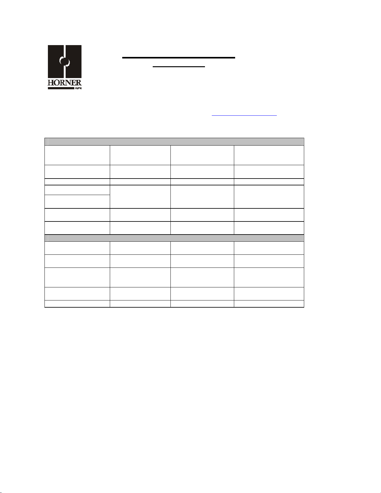
1 SPECIFICATIONS
ANALOG IN
Number of input
points
Input Ranges
Resolution 14 bits Isolation Method Magnetic
Accuracy, 25°C 0.1%
Input Impedance
Register Value for
Nominal Full Scale
Conversion Time 10ms for all
GENERAL
Required Power
(Steady State)
Required Power
(Inrush)
Atmosphere
Cooling method Self-cooling
Altitude for use Up to 2,000m Weight 8.0 oz. (227 g)
(75mA @ 24VDC)
Free from corrosive
gases and excessive
12
±5, ±10V DC
4-20, ±20mA DC
V: 1 Megohm
mA: 150 Ohms
32000
Channels
1.8W
8A @ 24VDC for
5ms
dust
Additional error for
temperatures other
than 25°C
Isolation
Maximum
Continuous
Overload
Programmable Filter
Time Constants
Filter Modes
Pollution degree 2 or lower
Operating
Temperature
Storage Temperature
Operating and
Storage Humidity
0.01% / °C
1000V DC
IEC61010-1 300V RMS
±10V: 150VAC
±20mA: ±30mA,
Clamped at ±6V
0.01 to 1.28 Seconds
Running Average or
Adaptive
0° to 55° C
-25° to 70° C
5 to 95% Non-
condensing
MAN0557-01
Page 2
PAGE 2 20 NOV 2003 ADC970
1.87
0.31
HExx9
-
With
Vibration
Occasional Vibration
Frequency Acceleration Amplitude
10 ≤ f < 57
Hz
57 ≤ f ≤ 150
Hz
- 0.075 mm
10 times in each direction for X,Y,Z
9.8 m/s2 {1G} -
Continuous Vibration
Frequency Acceleration Amplitude
10 ≤ f <
57 Hz
57≤ f ≤
150 Hz
- 0.035 mm
4.9 m/s
2
{0.5G}
10 times in each direction for X,Y,Z
-
Shocks
Maximum shock
acceleration
147 m/s2 {15G}
Duration Time 11 ms.
Pulse Wave Half sine wave pulse (3 times in each of X, Y, Z directions)
Sweep
Count
Sweep
Count
Noise Immunity
Square wave impulse noise
AC: ± 1,500VDC
DC: ± 900VDC
Electrostatic Discharge Voltage: 4kV (contact discharge)
Radiated electromagnetic
field
27 – 500MHz, 10V/m
Fast Transient
Burst Noise
Severity
level
All power
modules
Digital I/Os
(Ue ≥24V)
Communication I/Os
Voltage 2 kV 1 kV 0.25 kV
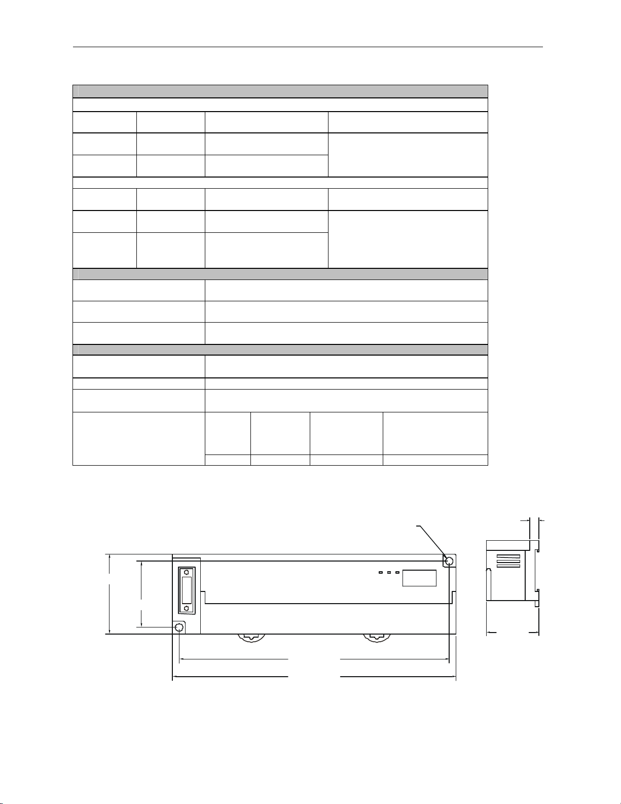
2 DIMENSIONS
0.18 [4.6mm]
1.97 [49.9mm]
1.62 [41.1mm]
6.61 [167.9mm]
6.95 [176.5mm]
Digital I/Os
(Ue < 24 V)
Analog I/Os
[7.9mm]
[47.5mm]
Removable
Terminal
Page 3
ADC970 20 NOV 2003 Page 3
** *
I11i
CNCI1v
I2iCI6v
I4v
I3v
I4i
I3i
I1iCI5iFGI5vCI6i
I7v
I8v
I7i
I8i
I9vCI9i
I11v
006ADC002
20mA
20mA
20mA
20mA
20mA
20mA
FT
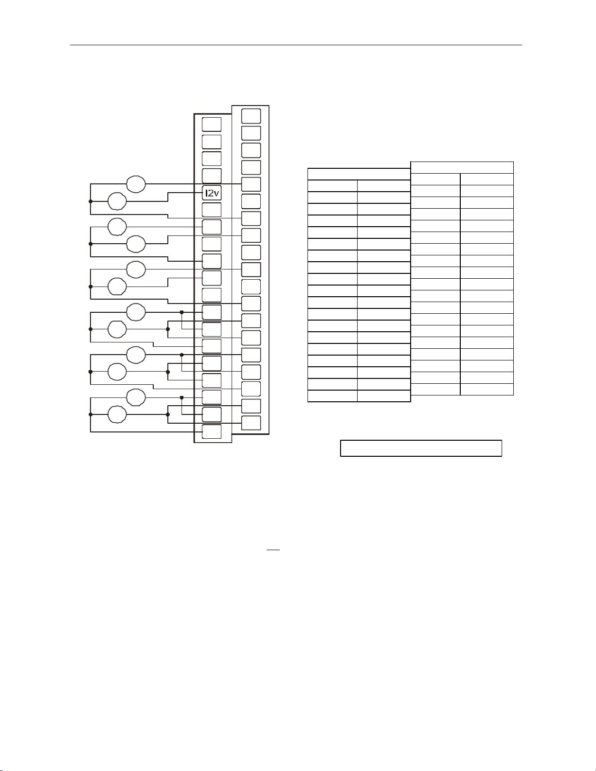
3 WIRING
+/- 10V
+/- 10V
FT
NC
NC
+/- 10V
+/- 10V
+/- 10V
+/- 10V
+/-
+/-
+/-
+/-
I10v
I10i
+/-
+/-
I12v
I12i
24+
24C
C
ADC970
2 FG
4 FT
6 NC
8 NC
10 I2v
12 I2i
14 I4v
16 I4i
18 C
20 I6v
22 I6i
24 I8v
26 I8i
28 C
30 I10v
32 I10i
34 I12v
36 I12i
38 C
ADC970
1 24+ *
3 24C **
5 FT
7 NC
9 I1v
11 I1i
13 C
15 I3v
17 I3i
19 I5v
21 I5i
23 C
25 I7v
27 I7i
29 I9v
31 I9i
33 C
35 I11v
37 I11i
FT: Factory Test, Do Not Connect
C terminals are connected together internally but isolated from bus and power circuits.
* and * * For CsCAN and DeviceNet versions, module power is usually derived from the CAN connector.
In that case, +24VDC and 24C are not connected.
Page 4

PAGE 4 20 NOV 2003 ADC970
To
Field
Voltage
Current
Isolated
+
4 INTERNAL WIRING
I/O Connector
SmartStack Inputs
Input
700KΩ
Side
Input
Common
6V
300KΩ
150Ω
_
Controller
5 INPUT MODE AND PRO GRAMMABLE FILTER CONFIGURATION
The network supplies configuration information to the HE550ADC970 in the Consumed Directed Digital
Data Words sent to the HE550ADC970. In the first word, the low 12 bits, 1 through 12, are channel mode
bits. A low mode bit selects ±10V and a high mode bit selects ±20mA. The next three bits, 13 through
15, are input digital filter time constant codes and the high bit, 16, is an adaptive filter enable bit. In the
second word, the low 12 bits are channel scale bits. A low scale bit selects ±10V or ±20mA for the
corresponding channel. A high scale bit selec ts ±5V or 4-20mA. The upper four bits are unused.
Bit Channel
1 AI1
2 AI2
3 AI3
4 AI4
5 AI5
6 AI6
7 AI7
8 AI8
9 AI9
10 AI10
11 AI11
12 AI12
Page 5

ADC970 20 NOV 2003 Page 5
Each analog input on the HE550ADC970 has a single pole 345Hz (461uS) cutoff high frequency noise
filter. In addition a second digital filter may be specified in the first configuration word with the following
time constants.
Bit
15 14 13
0 0 0 10 milliseconds (Nominal hardware scan rate)
0 0 1 15 milliseconds
0 1 0 35 milliseconds
0 1 1 75 milliseconds
1 0 0 155 milliseconds
1 0 1 315 milliseconds
1 1 0 635 milliseconds
1 1 1 1.275 seconds
This digital filter is useful for applications with significant amounts of random noise. The slower time
constants, while yielding bet ter noise suppression, take a longer time to settle after step changes and are
also sensitive to impulse noise which is treated like Gaussian noise and averaged.
Bit 16 of the first configuration word may be set to specify an adaptive filter algorithm that:
1. Responds much more quickly to large step changes at slower time constants with full filtering of low
level noise.
2. Suppresses impulse noise at the expense of slightly slower response at the shortest time constant
settings. (Approximately 10 additional milliseconds)
Note that actual system response time is network dependent.
See the SmartStix Programming Guide for more information.
Time Constant
6 INPUT CONVERSION FACTOR
The following table describes how real-world inputs are scaled into the controller. Given a known input
voltage or current, the register data value may be calculated by using the conversion factor from the
table. The following formula is used: Data = Voltage or Current In / Conversion Factor
Example: The user selects a voltage range of ±5 V:
1. The known input voltage is 3 VDC.
2. Using the table, the conversion factor for the voltage range of ±5 V is .00015625.
3. To determine the data value, the formula is used: Data = Vin / Conversion Factor
19200 = 3 VDC / 0.00015625
Page 6

PAGE 6 20 NOV 2003 ADC970
MS NS
Use this switch to set
Use this switch to set the
Conversion of Real-World Inputs into Register Values
Selected Range
Input
mA or Volts
Data Out Conversion Factor
> +5.11 32767
+5.00 32000
±5.00 V
0.00 0
0.00015625
-5.00 -32000
< -5.11 -32768
> +10.23 32767
+10.00 32000
±10.00 V
0.00 0
0.0003125
-10.00 -32000
< -10.23 -32768
< +20.37 32767
+20.00 32000
4.20 mA
+4.00 0
0.0005
-12.00 -32000
> -12.38 -32768
> +20.47 32767
+20.00 32000
±20.00 mA
0 0
0.0006250
-20.00 -32000
< -20.47 -32768
Note: For the 4 to 20mA range, the offset, 4mA, must first be subtracted from the physical input value
before dividing by the scale factor to yield the expected %AQG value for the given input.
7 SETTING ID SWITCHES
CsCAN Network IDs are set using the hexadecimal number system from 01 to FD. The decimal
equivalent is 1-253. Refer to following Conversion Table, which shows the decimal equivalent of
hexadecimal numbers. Set a unique Network ID by inserting a small Phillips screwdriver into the two
identical switches.
Note: The CsCAN Baud Rate for SmartStix I/O is fixed at 125KBaud
Power and Diagnostic
LEDs
High Digit –has an x16
multiplier.
the Low Digit – has an
x1 multiplier.
SmartStix I/O
PWR
HI (x16)
LO (x1)
006DIQ001
Close-up of Switches
Page 7

ADC970 20 NOV 2003 Page 7
Page 8

PAGE 8 20 NOV 2003 ADC970
Decimal (Dec) to Hexadecimal (Hex) Conversion
Dec Hex Dec Hex Dec Hex Dec Dec Hex
HI LO HI LO HI LO HI LO HI LO
54 3 6 108 6 C 162 A 2 216 D 8
1 0 1 55 3 7 109 6 D 163 A 3 217 D 9
2 0 2 56 3 8 110 6 E 164 A 4 218 D A
3 0 3 57 3 9 111 6 F 165 A 5 219 D B
4 0 4 58 3 A 112 7 0 166 A 6 220 D C
5 0 5 59 3 B 113 7 1 167 A 7 221 D D
6 0 6 60 3 C 114 7 2 168 A 8 222 D E
7 0 7 61 3 D 115 7 3 169 A 9 223 D F
8 0 8 62 3 E 116 7 4 170 A A 224 E 0
9 0 9 63 3 F 117 7 5 171 A B 225 E 1
10 0 A 64 4 0 118 7 6 172 A C 226 E 2
11 0 B 65 4 1 119 7 7 173 A D 227 E 3
12 0 C 66 4 2 120 7 8 174 A E 228 E 4
13 0 D 67 4 3 121 7 9 175 A F 229 E 5
14 0 E 68 4 4 122 7 A 176 B 0 230 E 6
15 0 F 69 4 5 123 7 B 177 B 1 231 E 7
16 1 0 70 4 6 124 7 C 178 B 2 232 E 8
17 1 1 71 4 7 125 7 D 179 B 3 233 E 9
18 1 2 72 4 8 126 7 E 180 B 4 234 E A
19 1 3 73 4 9 127 7 F 181 B 5 235 E B
20 1 4 74 4 A 128 8 0 182 B 6 236 E C
21 1 5 75 4 B 129 8 1 183 B 7 237 E D
22 1 6 76 4 C 130 8 2 184 B 8 238 E E
23 1 7 77 4 D 131 8 3 185 B 9 239 E F
24 1 8 78 4 E 132 8 4 186 B A 240 F 0
25 1 9 79 4 F 133 8 5 187 B B 241 F 1
26 1 A 80 5 0 134 8 6 188 B C 242 F 2
27 1 B 81 5 1 135 8 7 189 B D 243 F 3
28 1 C 82 5 2 136 8 8 190 B E 244 F 4
29 1 D 83 5 3 137 8 9 191 B F 245 F 5
30 1 E 84 5 4 138 8 A 192 C 0 246 F 6
31 1 F 85 5 5 139 8 B 193 C 1 247 F 7
32 2 0 86 5 6 140 8 C 194 C 2 248 F 8
33 2 1 87 5 7 141 8 D 195 C 3 249 F 9
34 2 2 88 5 8 142 8 E 196 C 4 250 F A
35 2 3 89 5 9 143 8 F 197 C 5 251 F B
36 2 4 90 5 A 144 9 0 198 C 6 252 F C
37 2 5 91 5 B 145 9 1 199 C 7 253 F D
38 2 6 92 5 C 146 9 2 200 C 8
39 2 7 93 5 D 147 9 3 201 C 9
40 2 8 94 5 E 148 9 4 202 C A
41 2 9 95 5 F 149 9 5 203 C B
42 2 A 96 6 0 150 9 6 204 C C
43 2 B 97 6 1 151 9 7 205 C D
44 2 C 98 6 2 152 9 8 206 C E
45 2 D 99 6 3 153 9 9 207 C F
46 2 E 100 6 4 154 9 A 208 D 0
47 2 F 101 6 5 155 9 B 209 D 1
48 3 0 102 6 6 156 9 C 210 D 2
49 3 1 103 6 7 157 9 D 211 D 3
50 3 2 104 6 8 158 9 E 212 D 4
51 3 3 105 6 9 159 9 F 213 D 5
52 3 4 106 6 A 160 A 0 214 D 6
53 3 5 107 6 B 161 A 1 215 D 7
Page 9

ADC970 20 NOV 2003 Page 9
+CN_LV-SHIELD
N_HV+CN_LV-SHIELDCN_HREDWHTBLUBLK121ΩV+CN_LV-SHIELDCN_HREDWHTBLUBLK
RED
WHT
RED
WHT
BLU
BLKV+CN_LV-SHIELDCN_H
001CAN002
8 LEDS
SmartStix I/O Modules provide diagnostic and status LED indicators.
a. Diagnostic LED Indicators
Diagnostic LED State Meaning
MS
(indicates fault status
of the Module )
NS
(indicates fault status
of the Network)
Solid Red RAM or ROM test failed
Blinking Red I/O test failed
Blinking Green Module is in power-up state
Solid Green Module is running normally
Solid Red Network Ack or Dup ID test failed
Blinking Red Network ID test failed
Blinking Green Module is in Life Expectancy default state
Solid Green Network is running normally
b. Status LED Indicators
The Power Status LED illuminates Red when power is applied to the module. There are I/O Status LED
indicators for each of the Digital I/O points, which illuminate Red when an I/O point is ON.
9 NETWORK CABLE
For detailed wiring information, refer to Chapter Two in the Control Station Hardware Manual
(MAN0227). A handy checklist is provided that covers panel box layout requirements and minimum
clearances.
Pin Description
RED 1 V+
WHT 2 CAN_H
SHD 3 Shield
BLU 4 CAN_L
BLK 5 V-
Recommended Cable
Thick: (Max Distance = 500m) Belden 3082A
Thin: (Max Distance = 100m) Belden 3084A
V
C
Ω
RED
121
-
+
12-25VDC
BLK
BLK
BLU
BLU
WHT
WHT
SHIELD
RED
RED
SHIELD
BLK
BLU
SHIELD
CAN Wiring
Note: 12 - 24VDC must be supplied to the network.
Page 10

PAGE 10 20 NOV 2003 ADC970
10 INSTALLATION / SAFETY
a. All applicable codes and standards need to be followed in the installation of this product.
b. For I/O wiring (discrete), use the following wire type or equivalent: Belden 8441 or equivalent.
c. For detailed installation information, refer to Chapter Two in the Control Station Hardware Manual
(MAN0227). A handy checklist is provided that covers panel box layout requirements and
minimum clearances.
Warning: Consult user documentation.
Warning: Electrical Shock Hazard.
11 TECHNICAL ASSISTANCE
For assistance, contact Technical Support at the following locations:
North America:
(317) 916-4274
www.heapg.com
Europe:
(+) 353-21-4321-266
www.horner-apg.com
 Loading...