

Page 1
OCX510 10 MAR 2003 PAGE 1
Mixed I/O Module
12/24 Vdc In, Positive/Negative Logic
HE500OCX510
3A Relay Out
Mini OCS/RCS
1 SPECIFICATIONS
INPUT
Inputs per Module 16 isolated Minimum ON Current 1mA
Isolated Commons
per Module
Input Voltage Range 12/24VDC OFF to ON Response 1ms.
Peak Voltage 35VDC Max. ON to OFF Response 1ms.
ON Voltage level Min. 9VDC
OFF Voltage level Max. 3VDC
Input Impedance
OUTPUT
Outputs per Module
Isolated Commons
per Module
Output Type Relay Minimum Load None
Coil Voltage
Contact Voltage
ON Voltage drop 0.2V Max.
250VAC / 30VDC Max.
3
> 10K Ohms
12 relay
4
20-28VDC
General Specifications
Required Power
(Steady State)
Required Power (Inrush) 770 mA @ 10ms.,
Relative Humidity 5 to 95%
Operating Temperature
230mA @ 24VDC
24VDC
Non-condensing
0° to 50° Celsius
Maximum OFF Current
Isolation between
Common and Ground
Maximum Load current
(resistive) per
output
Maximum Inrush Current
Isolation (Channel to
Channel and Channel to
Common)
Maximum Leakage
Current
UL
CE
Terminal
Type
Weight 9.5 oz. (270 g)
Please refer to Compliance Table located at
http://www.heapg.com/Support/compliance.htm
Spring Clamp, Removable
500VDC
200µA
3A
5A
500VDC
5µA
MAN0574-01
Information is subject to change without notice. Sm artStack is a trademark of Horner APG, LLC.
Page 2
PAGE 2 10 MAR 2003 OCX510
*
*
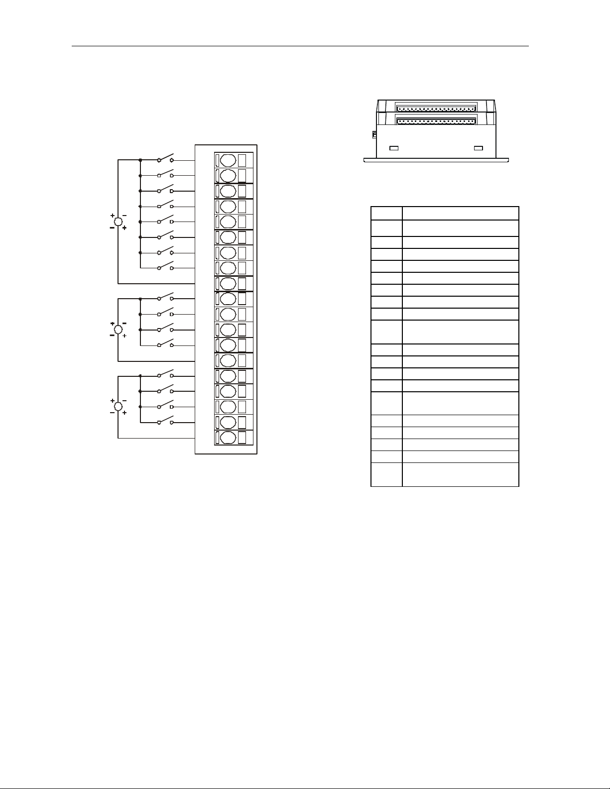
Mini Input Connector
2 WIRING
2.1 Input Connector Wiring
12-24VDC
12-24VDC
12-24VDC
I1
I2
I3
I4
I5
I6
I7
I8
C1
19
I10
I11
I12
C2
I13
I14
I15
I16
C3
001OCX002
(top connector only) – Shows
corresponding I/O pin location
Pin Signal
*I1
I2 Input 2
I3 Input 3
I4 Input 4
I5 Input 5
I6 Input 6
I7 Input 7
I8 Input 8
C1
I9 Input 9
I10 Input 10
I11 Input 11
I12 Input 12
C2
I13 Input 13
I14 Input 14
I15 Input 15
I16 Input 16
C3
inputs 9-12 (isolated)
inputs 13 -16 (isolated)
Input 1
Input common for
inputs 1-8 (isolated)
Input common for
Input common for
Information is subject to change without notice. SmartStack is a trademark of Horner APG, LLC.
Page 3

OCX510 10 MAR 2003 PAGE 3
*
Mini Output Connector
Warning: Wiring the line side of the AC source to loads connected to outputs 1 through 12 and the
*
2.2 Output Connector Wiring
5-250VAC
OR
5-30VDC
5-250VAC
OR
5-30VDC
5-250VAC
OR
5-30VDC
5-250VAC
OR
5-30VDC
20-28VDC
LOAD
N
L
N
L
N
L
N
L
LOAD
LOAD
LOAD
LOAD
LOAD
LOAD
LOAD
LOAD
LOAD
LOAD
LOAD
Q1
Q2
Q3
C4
Q4
Q5
Q6
C5
Q7
Q8
Q9
C6
Q10
Q11
Q12
C7
NC
VC
V+
001OCX001
(bottom connector only) – Shows
corresponding I/O pin location
Pin Signal
*Q1
Output 1
Q2 Output 2
Q3 Output 3
C4
Output common for
Outputs 1-3 (Isolated)
Q4 Output 4
Q5 Output 5
Q6 Output 6
C5
Output common for
Outputs 4-6 (Isolated)
Q7 Output 7
Q8 Output 8
Q9 Output 9
C6
Output common for
Outputs 7-9 (isolated)
Q10 Output 10
Q11 Output 11
Q12 Output 12
Output common for
C7
Outputs 10 -12
(isolated)
NC No Connection
Relay power common,
VC
connected internally to
digital ground
V+
Relay power, 20 -
28VDC, 100ma nominal
Warning: To protect the module and associated wiring from load faults, use external fuse (10 A) as
shown.
Warning: Connecting high voltage to any I/O pin may cause high voltage to appear at other I/O pins.
neutral side of the AC source to the output common(s) would create a Negative Logic
condition, which may be considered an unsafe practice.
Information is subject to change without notice. Sm artStack is a trademark of Horner APG, LLC.
Page 4

PAGE 4 10 MAR 2003 OCX510
To
Field
+
Q1
Q2
Q3
C2
Field
3 INTERNAL CIRCUIT SCHEMATIC
Specification for transient voltage suppressors (transorbs) used on output circuitry is 400VDC
bi-directional 400 watts.
Note: Electro-mechanical relays comply with IEC1131-2.
Input Connector
I1
Side
C
Side
Output Connector
Mini
VCC
Controller
Mini
+20-28V
-
+
-
-
+
4 CONFIGURATION
Note: The status of the I/O can be monitored in Cscape Software.
Selecting the I/O Map tab provides information about the I/O registers. The I/O Map is not edited by the
user.
The Module Setup is used in applications where it is necessary to change the default states of the
outputs when the controller (e.g., Mini) enters idle/stop mode. The default turns the outputs OFF when
the controller enters idle/stop mode. By selecting the Module Setup tab, each output can be set to either
turn ON, turn OFF or to hold the last state. Generally, most applications use the default settings.
Information is subject to change without notice. SmartStack is a trademark of Horner APG, LLC.
Page 5

OCX510 10 MAR 2003 PAGE 5
Warning: The default turns the outputs OFF when the controller enters idle/stop mode. To avoid
Digital Input Chart
Warning: Previous versions of this product provided internal fuses on the output
injury of personnel or damages to equipment, exercise extreme caution when changing the default
setting using the Module Setup tab.
5 INSTALLATION / SAFETY
a. All applicable codes and standards are to be followed in the installation of this produc t.
b. Use the following wire type or equivalent: Belden 8917, 16 AWG or larger.
For detailed installation information, refer to Mini Hardware Manual. A handy checklist is provided that
covers panel box layout requirements and minimum clearances.
circuits (relay contacts). Due to CE Low Voltage Directive (LVD) marking
requirements, these fuses have been removed and replaced with solid
wire. Therefore, it is now the responsibility of the user of this equipment
to ensure that adequate fusing is installed externally on each relay output
circuit.
Warning: Consult user documentation.
Warning: Electrical Shock Hazard.
6 INPUT / OUTPUT CHA RACTERISTICS
0.125(±±15%) V-A
0
35VDC
7 TECHNICAL SUPPORT
North America:
(317) 916 -4274
www.heapg.com
Europe:
(+) 353-21-4321-266
www.horner-apg.com
Information is subject to change without notice. Sm artStack is a trademark of Horner APG, LLC.
Page 6

PAGE 6 10 MAR 2003 OCX510
NOTES
Information is subject to change without notice. SmartStack is a trademark of Horner APG, LLC.
 Loading...