

Page 1
MAN0838-04-EN Specifications / Installation
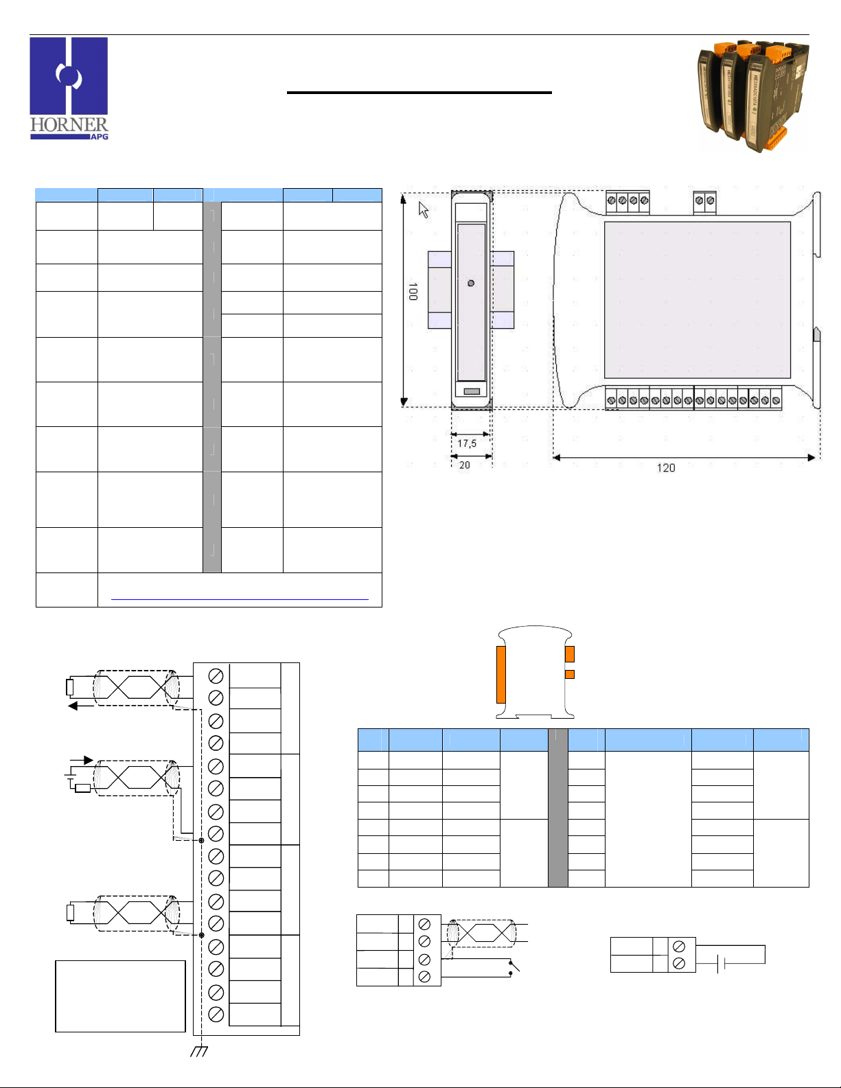
SmartMod
1
µA or
1 mV Resolution
1 Specifications
DAC007 DAC107 DAC007 DAC107
Number of
Channels
Output
Ranges
Resolution 1 µA or 1 mV
Load
Resistance
Output
Calibration
External
Power
Supply
Voltage
Required
Power
(Steady
State)
Required
Power
(Inrush)
Isolation
CE & UL
Compliance
2 4
0-20mA or 0-10V
Voltage: >5Kohm
Current: <500ohm
Voltage: +/-10mV
Current: +/-20uA
18-30Vdc Weight 150g (6 oz.)
30mA @ 24Vdc,
typical
(100mA max)
Negligible
2000Vac for 60
seconds
(Input/Power &
Input/Comms)
See Compliance Table at
http://www.heapg.com/Pages/TechSupport/ProductCert.html
Auxiliary
Voltage
Terminal
Type
Storage
Temp.
Operating
Temp.
Relative
Humidity
Dimensions
WxHxD
Communica-
tions
Factory
Default
Communica-
tions
Parameters
Supported
Modbus
Commands
(family)
Analog Output Module
-40° to 85° Celsius
-10° to 60° Celsius
RS-485 half duplex
38400 baud, N, 8, 1,
Default Modbus ID 1
1,2,3,4,5,6,8,15,16
2 Wiring – I/O
1
I
2
AUX
ACTIVE
3
IN
0
V
LOOP
4
GNA
5
I
6
AUX
PASSIVE
LOOP
+
VOLTAGE
NOTE: EACH
CHANNEL MAY BE
WIRED
INDEPENDENTLY
7
8
9
10
11
12
13
14
15
16
V
GNA
I
AUX
V
GNA
I
AUX
V
GNA
IN
1
IN
2
IN
3
HE359DAC007 / HE359DAC107
Selectable 0-20mA or 0-10V
12V @ 20mA (4
channels)
Screw Type,
Removable
5 to 95% Non-
condensing
17.5mm x 100mm
x 120mm
0.69” x 3.94” x
4.72”
Modbus/RTU
(binary)
no h/s
Notes:
Both ends of the RS-485 network should be terminated with a 100ohm, 1/4W, 1% resistor. Many OCS controllers
feature dip switches or jumpers which enable appropriate termination if the OCS is located on a network end.
Pin
DAC007 DAC107
#
1 I I 9 I
2 AUX AUX 10 AUX
3 V V 11 V
4 GNA GNA
5 I I 13 I
6 AUX AUX 14 AUX
7 V V 15 V
8 GNA GNA
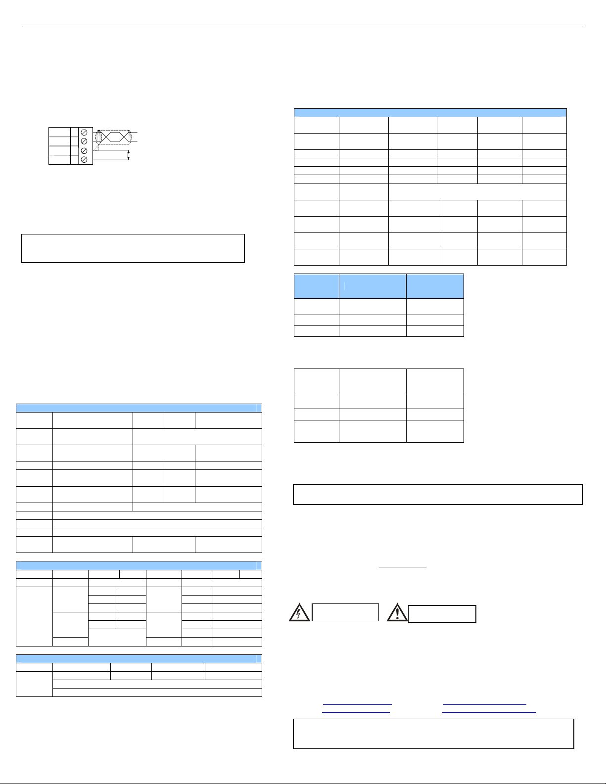
DD+
GND
INIT
A
B
C
D
Dimensions in inches are 0.69”W x 3.95”H x 4.72”D
Note: Number of I/O terminal connections vary from model to model
RS-485
I/O
OUT 0
OUT 1
Wiring RS-485
DC IN
Pin
#
12 GNA
16
DAC007 DAC107
Only Terminals
1 through 8 are
present on the
DAC007 model
VV+
Wiring DC IN
I
J
GNA
10-30Vdc
OUT 2
OUT 3
__________________________________________________________________________________________________________________________________________________________________
5/11/2009 Page 1 of 2 ECN # 950
Page 2
MAN0838-04-EN Specifications / Installation
0 = 7 Data
1 = 8 Data
INIT
3 Init Default Setup
Communication parameters will be set to INIT default after performing the
procedure:
1. Install jumper between INIT and GND terminals of the RS-485 port.
2. Apply power to Smartmod unit.
3. Read parameter words to see current parameters.
4. Write changes if necessary.
The INIT Default RS485 Settings Are:
Modbus ID = 1
Baud rate = 9600
Parity = None
Stop Bits = 1
Data Bits = 8
No handshake
Note: There are 2 types of default settings possible:
1. Factory default as described in section 1 (Specifications)
2. Default after INIT as described in section 3 (INIT Default Setup)
4 Configuration DATA
SmartMod Configuration settings are mapped into Modbus Register space. This
configuration data may be modified with any Modbus/RTU Master device. For
convenience, Horner APG has developed a variety of Cscape application files
which allow an OCS (Xle, NX, LX, QX) to act as a SmartMod configurator. Initial
configuration of SmartMod module should be done on an individual basis, since
all modules come from the factory with a default Modbus ID of 1. Once each
module on the network has its own unique Modbus ID, further configuration
adjustments can be made with the entire network powered.
All configuration parameters listed below (except 40012 Channel Enable) are
stored in EPROM. That means they should not be constantly rewritten.
Configuration Parameters – Registers 40001 through 40013
Modbus
Register
40001-
40005
40006
40007 Modbus ID 1 255 1
40008
40009
40010 Modbus Coil Data Not Configuration Data – See I/O Data
40011 Reserved
40012 Reserved
40013 Reserved
40014 Output Type See Table
Register 40006 (Communications Parameters) Bit Definition
Bits 7-15 Bit 6 Bit 5 Bit 4 Bit 3 Bit 2 Bit 1 Bit 0
Unused Mode Parity Data Bits
Bit 4-15 Bit 3 Bit 2 Bit 1 Bit 0
Unused
A
D-
B
D+
C
GND
D
Description Min Max
Reserved
Communications
Parameters
Rx/Tx Delay (in 2mS
steps)
Watchdog Timer (in
0.5s steps)
0 = ASCII
Mode
1 = RTU
Mode
Value Meaning
0 Mark 0 1200 baud
1 Even
2 Odd 2 4800 baud
3 Space 3 9600 baud
Register 40014 (Output Type) Bit Definition
Output 3 Output 2 Output 1 Output 0
See Table
0 255 0mS
0 255 10 (5s)
Bits
Bits
5-7 38400 baud
0 = Current (0-20mA)
1 = Voltage (0-10V)
38.4kbaud, N, 8,
1, RTU Mode
0 (All Channels
Baud Rate
Value Meaning
1 2400 baud
4 19200 baud
Default
Current)
5 Input/Output DATA
SmartMod Analog I/O utilizes both Modbus Registers (40001-40030) and Coils (1-11). It is
possible to access all data using Registers only, because the Coils can be accessed through
Register 40010.
The following tables lists all Modbus I/O data available.
Modbus
Register Description Access Minimum Maximum Units
40010
40015 Output 0 Read/Write 0 20000 1uA or 1mV
40016 Output 1 Read/Write 0 20000 1uA or 1mV
40017 Output 2 Read/Write 0 20000 1uA or 1mV
40018 Output 3 Read/Write 0 20000 1uA or 1mV
40019-
40022
40023
40024
40025
40026
Modbus
Coil
00009
00010 Watchdog Event Read/Write
00011 Power-up Event Read/Write
Modbus
Register
40010 bit 0
40010 bit 1 Watchdog Event Read/Write
40010 bit 2 Power-up Event Read/Write
6 Installation / safety
Warning: Remove power from the OCS controller, CAN port, and any peripheral
equipment connected to this local system before adding or replacing this or any module.
a. All applicable codes and standards should be followed in the installation of this product.
b. Shielded, twisted-pair wiring should be used for best performance.
c. Shields may be terminated at the module terminal strip.
d. In severe applications, shields should be tied directly to the ground block within the panel.
e. Use the following wire type or equivalent: Belden 8441.
For detailed installation and a handy checklist that covers panel box layout requirements and
minimum clearances, refer to the hardware manual of the controller you are using.
When found on the product, the following symbols specify:
7 Technical Support
Warning: Electrical
Shock Hazard.
I/O Register Data (Registers 40010-40026)
Mirror of
Coil Data
Reserved
Default/Safe
Value Out 0
Default/Safe
Value Out 1
Default/Safe
Value Out 2
Default/Safe
Value Out 3
Description Access
Watchdog
Enabled
Description Access
Watchdog
Enabled
Read/Write n/a n/a n/a
Read/Write 0 20000 1uA or 1mV
Read/Write 0 20000 1uA or 1mV
Read/Write 0 20000 1uA or 1mV
Read/Write 0 20000 1uA or 1mV
Read/Write
Read/Write
Warning: Consult
user documentation.
Watchdog Event &
Power-up Event
Operation
If Coil 9 (Watchdog
Enabled) is set, Coil 10
(Watchdog Event) will set
if the Watchdog Timeout
value is exceeded. The
Watchdog Timeout value
is set in Register 40009.
When set, Coil 10 can be
reset by the controller
when normal
communications
resumes.
The Power-up Event
(Coil 11) is set every time
the power is applied. It
can be cleared by the
controller if desired.
Technical Support at the following locations:
North America:
Tel: 317 916-4274
Fax: 317 639-4279
Web: http://www.heapg.com
Email: techsppt@heapg.com
No part of this publication may be reproduced without the prior agreement and written
permission of Horner APG, Inc. Information in this document is subject to change without
notice.
Europe:
Tel: +353-21-4321266
Fax: +353-21-4321826
Web: http://www.horner-apg.com
Email: tech.support@horner-apg.com
__________________________________________________________________________________________________________________________________________________________________
5/11/2009 Page 2 of 2 ECN # 950
 Loading...