

Page 1
Application Bulletin
August 3. 2007
Garmin GPS to XLe
Garmin GPS to XLe Application Note
Overview
The HE200GPS183 GPS Receiver (GPS183) is an OCS accessory that provides a variety of GPS data to the control
system with a high degree of accuracy. GPS stands for “Global Positioning System” – which consists of a set of earthorbiting satellites and ground stations. GPS allows a portable receiver to calculate with a high degree of accuracy its
current position, time, velocity, etc.
The GPS183 uses NMEA0183 protocol – which is a standard established by the National Marine Educators
Association. The GPS183 utilizes RS-232 for data communications, and is powered by 5Vdc. Most OCS models (NX,
LX, QX) provide an appropriate 5V output on their serial ports. The XLe does not feature a 5V output – it requires an
external 5V, 60mA power supply to power the GPS183.
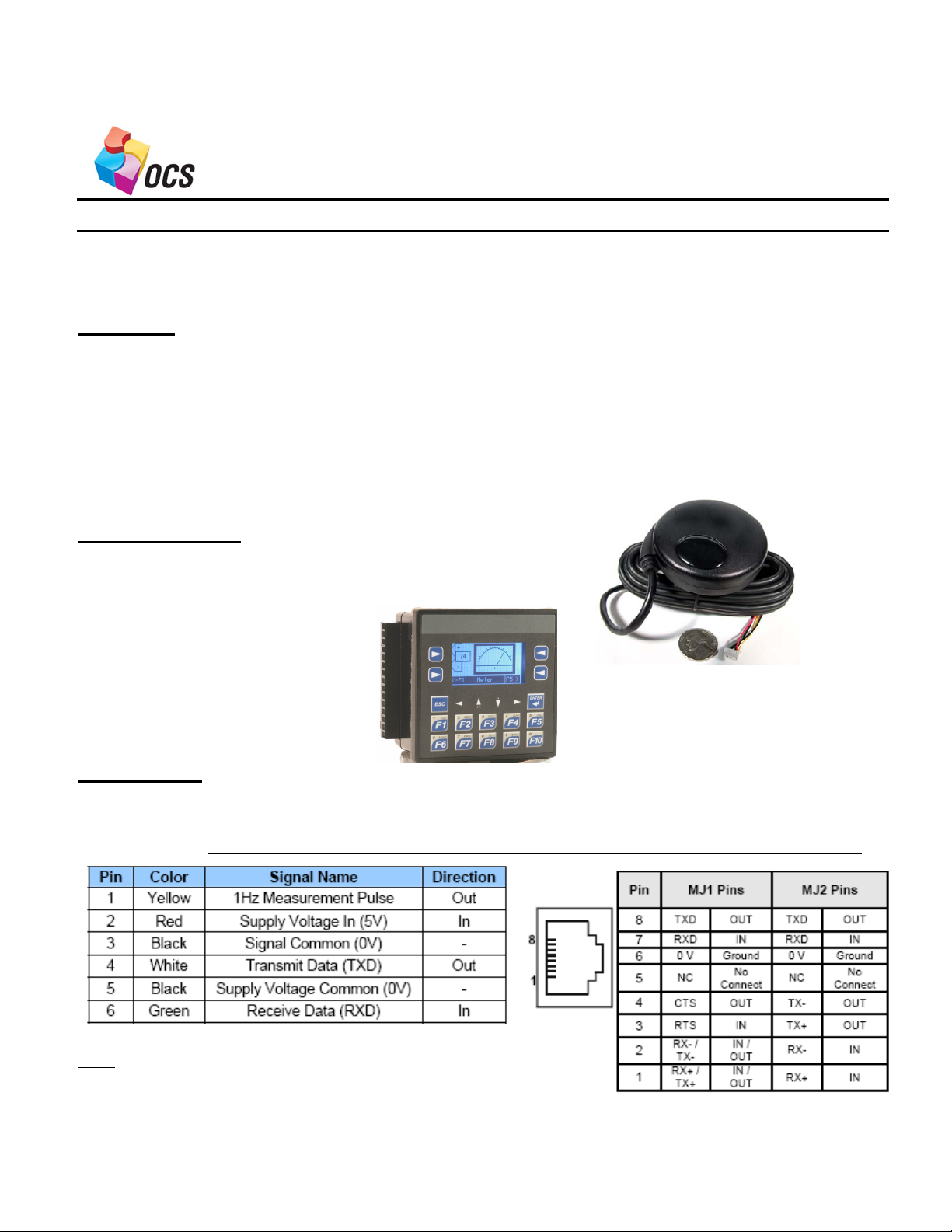
Products used:
HE200GPS183 Horner GPS
HE-XE105 Horner XLe
References:
Horner GPS Manual MAN0857-01
XLE Hardware Manual MAN0808-01, 0809-01 and 0810-01
GPS Cable Pin out XLe Port Pin out
Note:
1. The Yellow wire from the GPS is NOT used
2. The Thicker Black wire is for the supply voltage
common
3. The XLe pin out is for the port, NOT the cable connector
Page 2
Wiring Diagram
GPS XLe(MJ2)
1 Yellow (Not Used)
2 Red ---------------------------------------------- Supply Voltage 5 VDC
3 Black (small) ---------------------------------- 6 Ground
4 White ------------------------------------------- 7 RXD
5 Black (Thick) ---------------------------------- Supply Voltage Common (0V)
6 Green -------------------------------------------- 8 TXD
Configuration inside of CsCAPE (v8.10 or higher)
Use comm. Port 2 (MJ2) on the XLe. This will keep you programming port (MJ1) available for CsCAPE programming,
diagnostics, and troubleshooting.
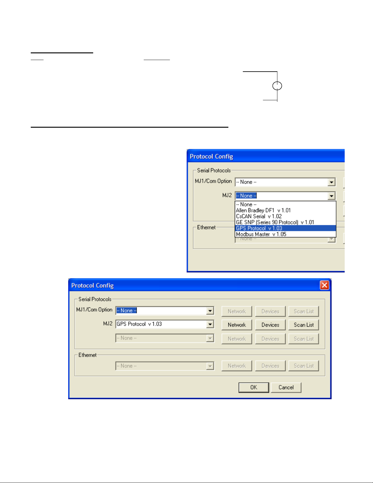
Use CsCAPE to set MJ2 protocol to the GPS protocol
1. Open CsCAPE
2. Set the hardware configuration to your
model of XLe
3. Select Program then Protocol Config…
4. From the drop down list on MJ2 select
GPS Protocol v1.03
This will add the GPS Protocol to the MJ2
field. You are now ready to start the three
steps required for any protocol
configuration
5 VDC
+
-
Page 3

5. The first step is to set the Network Setup parameters. This is to configure the comm. Port settings.
Baud Rate, Parity, Data Bits, Stop Bits, Handshaking, Protocol, RS232 or RS485, Scan Update Rate,
Timeout and retries. All of these parameters are defaulted to the correct parameters. The only thing you
need to set in this box is the Status Registers. I used %R1 for this demo. This will give you
information about the status of the communications between the GPS and the XLe on MJ2.
Page 4
6. The second tab is to configure the
device. In this case there is only one
device and this has been done for
you. With the GPS protocol
selected, you will not be able to
select this tab.
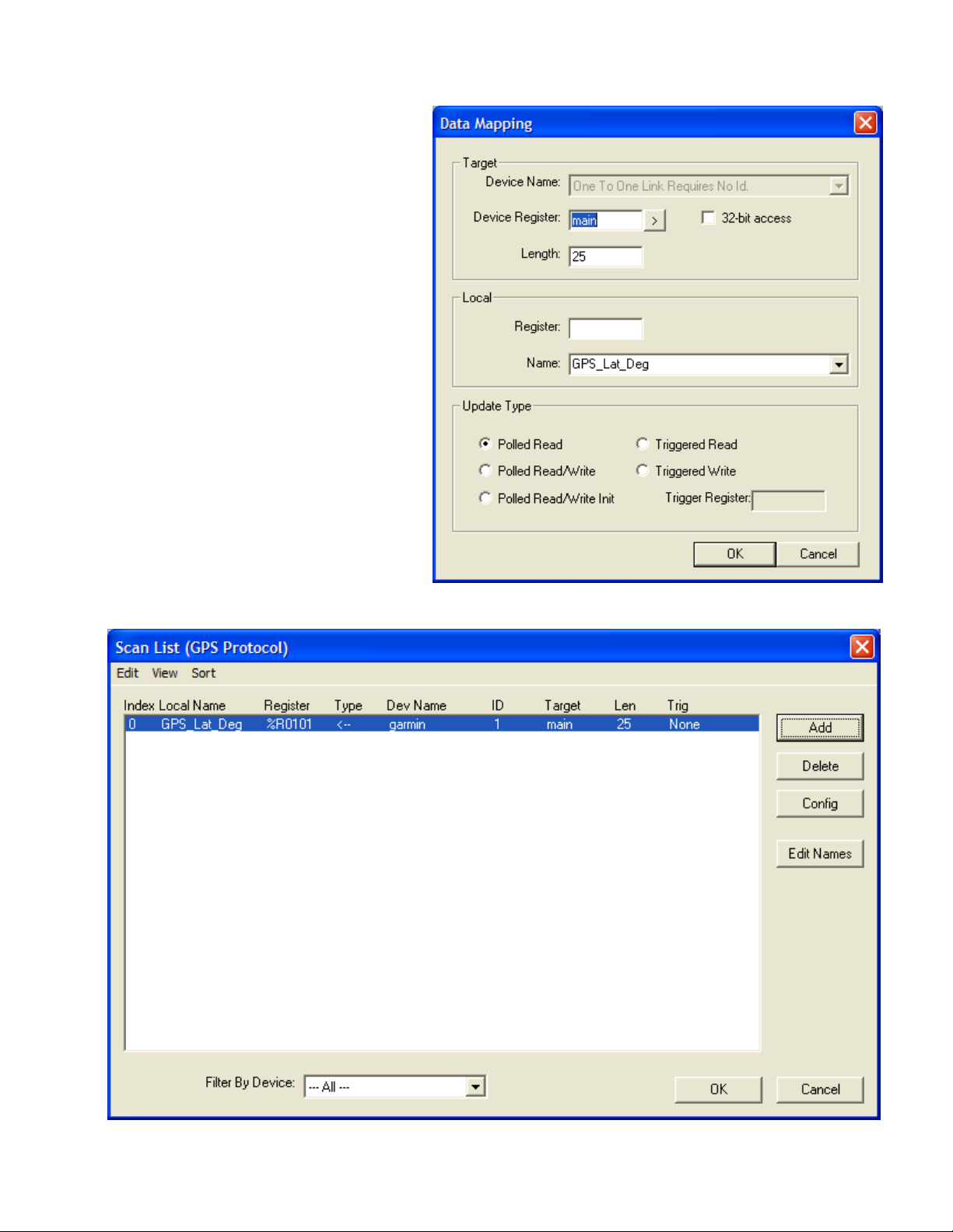
7. The last step in the protocol setup is
to set the scan list.
Click this tab and select the Add
Button.
You only need to fill in two fields in
this area.
Set the Length (number of words)
to 25
Set the Local Register Address (I
used %R101).
Note that the Target-Device Register
defaults to main. You do not need to
fill this in
8. Click OK. You should see your scan list updated to the following
Page 5
9. Click OK to accept the Scan List
10. Click OK to Accept the Protocol Configuration.
You are now done with the protocol setup
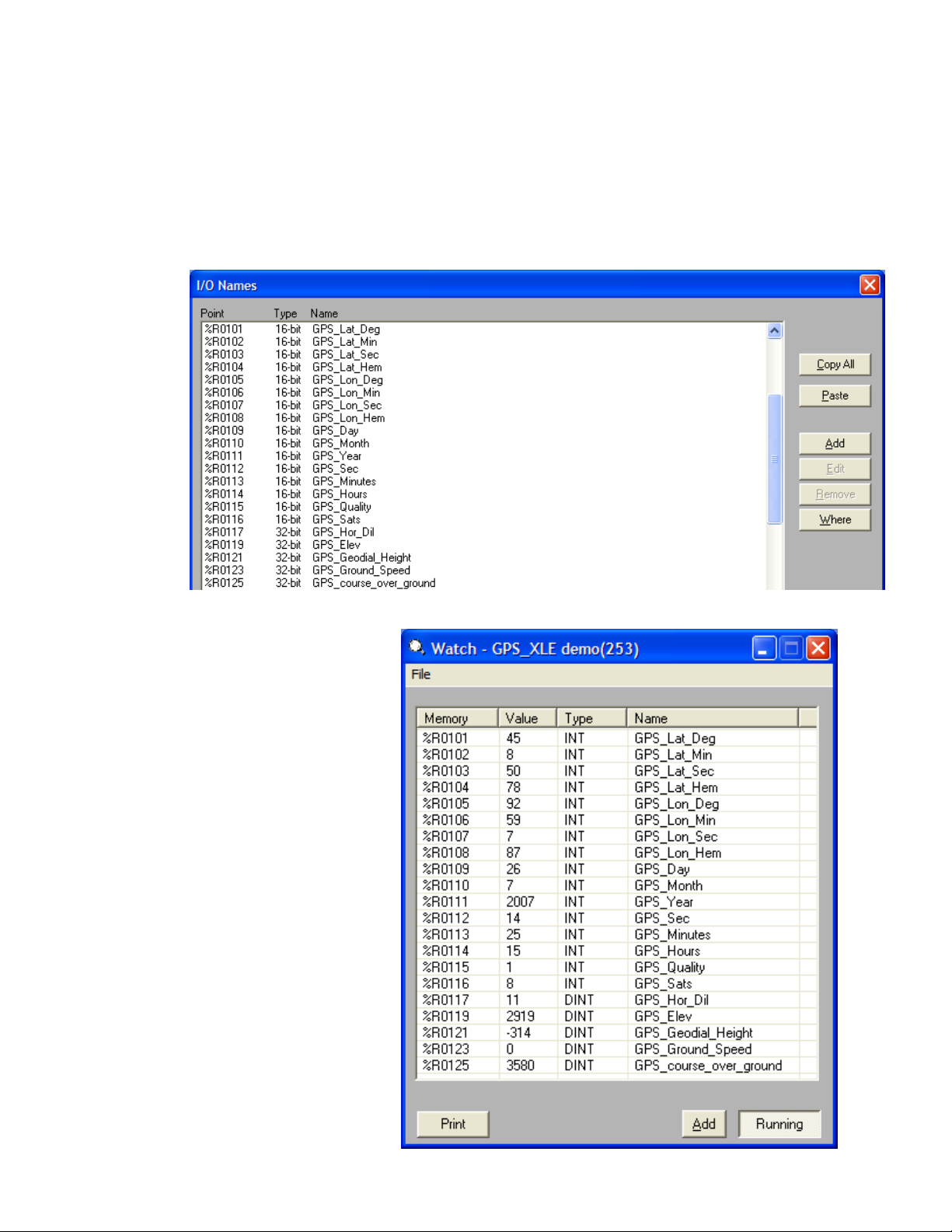
11. The next step is to do the I/O Name setup for all of the GPS data. This data will start at %R101 and go
through %R125.
See Table below for actual GPS data descriptions: (The GPS Manual will also give you detailed
descriptions, Ranges, and engineering units for each data point)
12. Create a Data Watch window
with all of the GPS data in it.
See this to the right:
Page 6

13. The last step is to use the GPS data in your Relay Ladder Logic, Data Logging or Display Screens.
See Examples of GPS Data on the XLe Screens Below:
Additional Information to Connect GPS to other OCS X Products (see Below table)
Summary
Horner APG wrote this document on August 3, 2007. Questions or comments can be directed to the Tech Support
Department by phone at 317-916-4274 or email techsppt@heapg.com.
 Loading...