

Page 1

User Manual for XL7 OCS
MAN0974-09-EN_XL7_UserManual
HE-XW1E0 / HEXT391C100
HE-XW1E2 / HEXT391C112
HE-XW1E3 / HEXT391C113
HE-XW1E4 / HEXT391C114
HE-XW1E5 / HEXT391C115
HE-XW1E6 / HEXT391C116
Page 2

MAN0974-09-EN_XL7_UserManual
March 4th, 2019 Page 2 | 185
PREFACE
This manual explains how to use the XL7 OCS.
Copyright© 2013 Horner APG, LLC, 59 South State Avenue, Indianapolis, Indiana 46201. All
rights reserved. No part of this publication may be reproduced, transmitted, transcribed,
stored in a retrieval system, or translated into any language or computer language, in any
form by any means, electronic, mechanical, magnetic, optical, chemical, manual or otherwise,
without the prior agreement and written permission of Horner APG, Inc.
All software described in this document or media is also copyrighted material subject to the
terms and conditions of the Horner Software License Agreement.
Information in this document is subject to change without notice and does not represent a
commitment on the part of Horner APG.
Cscape, SmartStack, SmartStix, SmartRail, SmartMod, and CsCAN are trademarks of Horner
APG.
Ethernet™ is a trademark of Xerox Corporation.
microSD™ and CompactFlash are registered trademarks of SanDisk Corporation.
For user manual updates, please visit our website:
North America:
Tel: (+) (317) 916-4274
Fax: (+) (317) 639-4279
Website: https://hornerautomation.com
Email: techsppt@heapg.com
Europe:
Tel: (+) 353-21-4321-266
Fax: (+) 353-21-4321-826
Website: http://www.horner-apg.com
Email: technical.support@horner-apg.com
Page 3

MAN0974-09-EN_XL7_UserManual
March 4th, 2019 Page 3 | 185
LIMITED WARRANTY AND LIMITATION OF LIABILITY
Horner APG, LLC, ("HE-APG") warrants to the original purchaser that the XL7 (HEXW/HEXT391) OCS module manufactured by HE-APG is free from defects in material and
workmanship under normal use and service. The obligation of HE-APG under this warranty shall
be limited to the repair or exchange of any part or parts which may prove defective under
normal use and service within two (2) years from the date of manufacture or eighteen (18)
months from the date of installation by the original purchaser whichever occurs first, such
defect to be disclosed to the satisfaction of HE-APG after examination by HE-APG of the
allegedly defective part or parts. THIS WARRANTY IS EXPRESSLY IN LIEU OF ALL OTHER
WARRANTIES EXPRESSED OR IMPLIED INCLUDING THE WARRANTIES OF MERCHANTABILITY
AND FITNESS FOR USE AND OF ALL OTHER OBLIGATIONS OR LIABILITIES AND HE-APG
NEITHER ASSUMES, NOR AUTHORIZES ANY OTHER PERSON TO ASSUME FOR HE-APG, ANY
OTHER LIABILITY IN CONNECTION WITH THE SALE OF THIS XL7 OCS module. THIS WARRANTY
SHALL NOT APPLY TO THIS XL7 OCS module OR ANY PART THEREOF WHICH HAS BEEN
SUBJECT TO ACCIDENT, NEGLIGENCE, ALTERATION, ABUSE, OR MISUSE. HE-APG MAKES NO
WARRANTY WHATSOEVER IN RESPECT TO ACCESSORIES OR PARTS NOT SUPPLIED BY HEAPG. THE TERM "ORIGINAL PURCHASER", AS USED IN THIS WARRANTY, SHALL BE DEEMED
TO MEAN THAT PERSON FOR WHOM THE XL7 OCS module IS ORIGINALLY INSTALLED. THIS
WARRANTY SHALL APPLY ONLY WITHIN THE BOUNDARIES OF THE CONTINENTAL UNITED
STATES.
In no event, whether as a result of breach of contract, warranty, tort (including negligence) or
otherwise, shall HE-APG or its suppliers be liable of any special, consequential, incidental or
penal damages including, but not limited to, loss of profit or revenues, loss of use of the
products or any associated equipment, damage to associated equipment, cost of capital, cost
of substitute products, facilities, services or replacement power, down time costs, or claims of
original purchaser's customers for such damages.
To obtain warranty service, return the product to your distributor with a description of the
problem, proof of purchase, postpaid, insured and in a suitable package.
ABOUT PROGRAMMING EXAMPLES
Any example programs and program segments in this manual or provided on accompanying
media are included solely for illustrative purposes. Due to the many variables and requirements
associated with any particular installation, Horner APG cannot assume responsibility or liability
for actual use based on the examples and diagrams. It is the sole responsibility of the system
designer utilizing the XL7 OCS module to appropriately design the end system, to appropriately
integrate the XL7OCS module and to make safety provisions for the end equipment as is usual
and customary in industrial applications as defined in any codes or standards which apply.
NOTE: The programming examples shown in this manual are for illustrative purposes only.
Proper machine operation is the sole responsibility of the system integrator.
Page 4
MAN0974-09-EN_XL7_UserManual
March 4th, 2019 Page 4 | 185
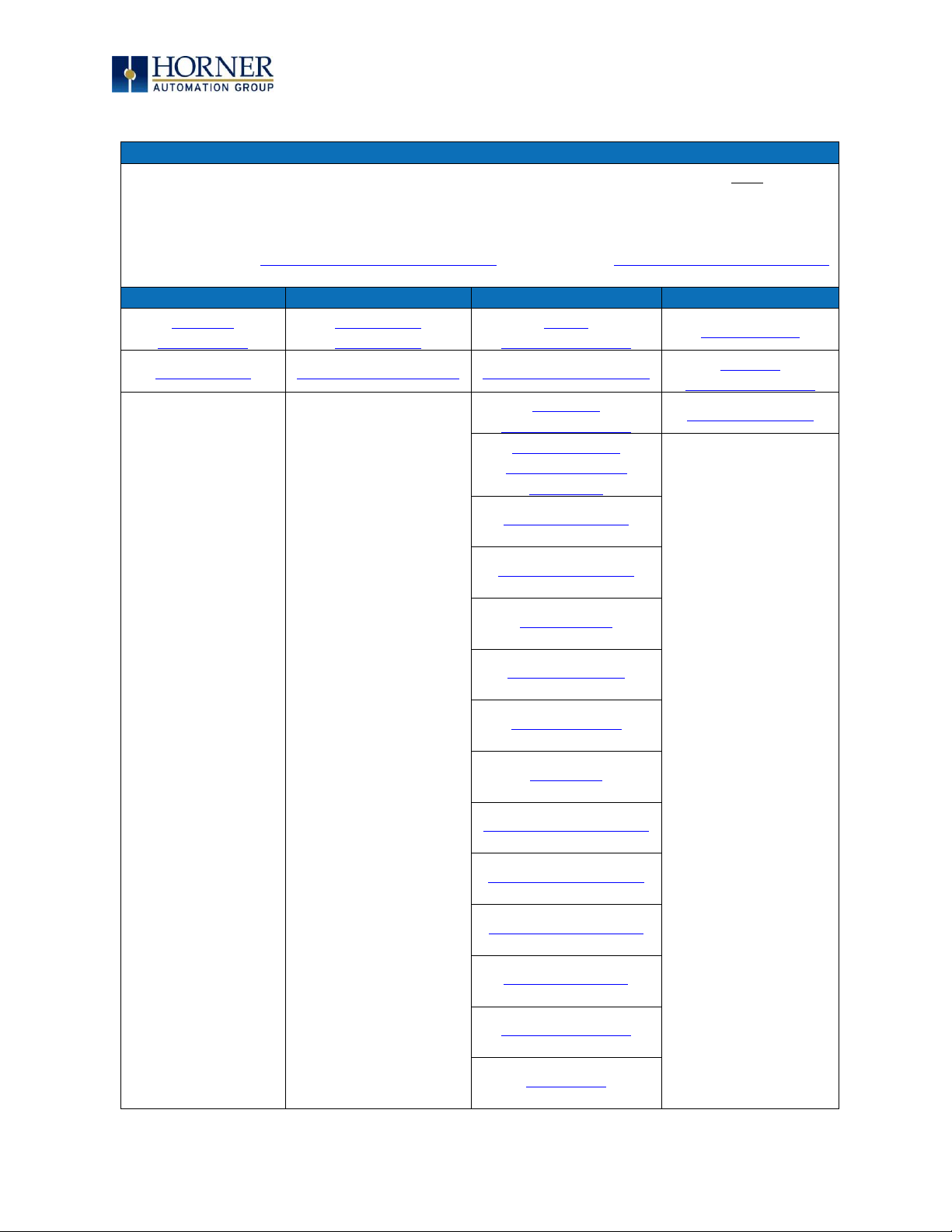
VISUAL MAP OF CHAPTERS
FIRST STEP of ANY TASK: DATASHEET
Each XL7 OCS unit is sent with a datasheet in the box. The datasheets are the first
documents to refer to for model-specific information related to XL7 OCS models for
specific installation information. To obtain updates to datasheets, manuals and user
documentation, visit a Horner website.
North America https://hornerautomation.com Europe http://www.horner-apg.com
QUICK START
INSTALLATION
PROGRAMMING
TROUBLESHOOTING
Safety /
Compliance
Mechanical
Installation
Serial
Communications
Maintenance
Introduction
Electrical Installation
CAN Communications
Modbus
Communications
Ethernet
Communications
Troubleshooting
Downloadable
Communication
Protocols
System Settings
Removable Media
General I/O
High-Speed I/O
User Interface
Registers
Cscape Configuration
Audio Configuration
Video Configuration
Back-up Battery
Fail-Safe System
Clone Unit
Page 5

MAN0974-09-EN_XL7_UserManual
March 4th, 2019 Page 5 | 185
TABLE OF CONTENTS
PREFACE ..................................................................................................................................................... 2
ABOUT PROGRAMMING EXAMPLES ....................................................................................................... 3
VISUAL MAP OF CHAPTERS .................................................................................................................... 4
TABLE OF CONTENTS ............................................................................................................................... 5
CHAPTER 1: SAFETY / COMPLIANCE .................................................................................................. 9
1.1 Safety Warnings and Guidelines ............................................................................................... 9
1.2 Grounding ...................................................................................................................................... 10
1.3 Compliance ................................................................................................................................... 10
CHAPTER 2: INTRODUCTION ................................................................................................................. 11
2.1 Visual Overview of XL7 OCS ...................................................................................................... 11
2.2 Connectivity to the XL7 OCS .................................................................................................... 13
2.3 Features of XL7 OCS .................................................................................................................. 14
2.4 Accessories ................................................................................................................................... 15
2.5 Useful Documents and References ......................................................................................... 15
2.6 Opening Cscape Help File .......................................................................................................... 15
CHAPTER 3: MECHANICAL INSTALLATION ...................................................................................... 16
3.1 Overview ........................................................................................................................................ 16
3.2 Mounting Requirements ............................................................................................................ 16
3.3 Mounting Orientation ................................................................................................................. 17
3.4 Panel Cut-Out ............................................................................................................................... 19
3.5 Factors Affecting Panel Layout Design and Clearances .................................................. 20
CHAPTER 4: ELECTRICAL INSTALLATION ...................................................................................... 22
4.1 Grounding Definition ................................................................................................................. 22
4.2 Ground Specifications ............................................................................................................... 22
4.3 How to Test for Good Ground ................................................................................................. 23
4.4 Primary Power Port ................................................................................................................... 24
CHAPTER 5: SERIAL COMMUNICATIONS ......................................................................................... 25
5.1 Overview ....................................................................................................................................... 25
5.2 Port Descriptions ........................................................................................................................ 25
5.3 Wiring and Dip Switches ........................................................................................................... 25
5.4 RS485 Termination ................................................................................................................... 26
5.5 RS485 Biasing ............................................................................................................................. 26
5.6 Cscape Programming via Serial Port .................................................................................... 27
5.7 Ladder-Controlled Serial Communication ............................................................................ 27
5.8 Configuration via Mini-B USB .................................................................................................. 27
CHAPTER 6: CAN COMMUNICATIONS............................................................................................... 28
6.1 Overview ....................................................................................................................................... 28
6.2 Port Description .......................................................................................................................... 28
6.3 CAN Port Wiring .......................................................................................................................... 29
6.4 Cscape Programming via CAN ................................................................................................ 29
6.5 Ladder-Controlled CAN Communication .............................................................................. 29
6.6 Using CAN for I/O Expansion (Network I/O) ........................................................................ 29
CHAPTER 7: ETHERNET COMMUNICATION ..................................................................................... 30
7.1 Ethernet Module Protocols and Features ............................................................................ 30
Page 6

MAN0974-09-EN_XL7_UserManual
March 4th, 2019 Page 6 | 185
7.2 Ethernet System Requirements ............................................................................................. 30
7.3 Ethernet Module Specifications .............................................................................................. 30
7.4 Ethernet Module Configuration ............................................................................................... 31
7.5 Ethernet Configuration – IP Parameters .............................................................................. 34
7.6 Ethernet Module Protocol Configuration ............................................................................. 34
CHAPTER 8: DOWNLOADABLE COMMUNICATION PROTOCOLS ............................................... 35
8.1 Overview ....................................................................................................................................... 35
8.2 Protocol Config ........................................................................................................................... 37
8.3 Network Configuration.............................................................................................................. 38
8.4 Device List and Device Configuration ................................................................................... 40
8.5 Scan List ........................................................................................................................................ 41
8.6 Data Mapping Configuration (Scan List Entry) ................................................................... 42
CHAPTER 9: SYSTEM SETTINGS AND ADJUSTMENTS ................................................................ 44
9.1 System Menu - Overview .......................................................................................................... 44
9.2 System Menu – Navigation and Editing ................................................................................. 45
9.3 System Menu – Details .............................................................................................................. 47
9.4 Touch screen calibration .......................................................................................................... 66
CHAPTER 10: REMOVABLE MEDIA ..................................................................................................... 67
10.1 Overview ....................................................................................................................................... 67
10.2 microSD Cards ......................................................................................................................... 67
10.3 microSD File System .............................................................................................................. 67
10.4 Using the Removable Media Manager ............................................................................... 68
10.5 Using Removable Media to Log Data ................................................................................. 68
10.6 Using Removable Media to Load and Save Applications .............................................. 69
10.7 Using Removable Media to View and Capture Screens ................................................ 69
10.8 Configuration of a Removable Media ................................................................................ 70
10.9 Removable Media (RM) Function Blocks in Cscape ........................................................ 70
10.10 Removable Media (RM) Features—Program Features .................................................... 71
10.11 Removable Media (RM) Features—Graphic/Screen Editor ............................................ 71
10.12 Removable Media (RM) Features—Additional Configuration ........................................ 71
10.13 Filenames used with the Removable Media (RM) Function Blocks ............................ 72
10.14 System Registers used with RM .......................................................................................... 73
CHAPTER 11: GENERAL I/O ................................................................................................................... 74
11.1 Overview ....................................................................................................................................... 74
11.2 Removing the XL7 OCS I/O Cover .......................................................................................... 74
11.3 Model and I/O Overview ........................................................................................................... 76
11.4 Solid-State Digital Outputs ...................................................................................................... 77
11.5 Relay Outputs .............................................................................................................................. 78
11.6 Digital Inputs................................................................................................................................ 80
11.7 Analog Inputs ............................................................................................................................... 81
11.8 Universal Analog Inputs ............................................................................................................ 82
11.9 Analog Outputs ........................................................................................................................... 83
CHAPTER 12: HIGH SPEED I/O (HSC / PWM) ................................................................................... 84
12.1 Overview ....................................................................................................................................... 84
12.2 Glossary ........................................................................................................................................ 85
12.3 High Speed Counter (HSC) Functions ................................................................................... 86
12.4 HSC Functions Register Map ............................................................................................... 94
12.5 High Speed Output Functions .............................................................................................. 97
12.6 High Speed Output Functions Register Map .................................................................... 101
Page 7

MAN0974-09-EN_XL7_UserManual
March 4th, 2019 Page 7 | 185
12.7 PWM Examples ...........................................................................................................................102
12.8 STP Examples ......................................................................................................................... 103
12.9 HSC I/O Filtering ................................................................................................................... 104
CHAPTER 13: USER INTERFACE ......................................................................................................... 107
13.1 Overview ...................................................................................................................................... 107
13.2 Screen Specifications ............................................................................................................... 107
13.3 Displaying and Entering Data ................................................................................................ 108
13.4 Alpha-numeric Keypad ........................................................................................................ 109
13.5 Screen Navigation ....................................................................................................................... 111
13.6 Ladder Based Screen Navigation ....................................................................................... 112
13.7 Beeper Acknowledgement ....................................................................................................... 112
13.8 Touch (Slip) Sensitivity ......................................................................................................... 113
13.9 Alarms ....................................................................................................................................... 114
13.10 Removable Media ................................................................................................................... 116
13.11 Screen Saver............................................................................................................................ 118
13.12 Screen Brightness .................................................................................................................. 118
13.13 Touch Screen Pressure ......................................................................................................... 119
CHAPTER 14: REGISTERS ..................................................................................................................... 121
14.1 Register Definitions ................................................................................................................... 121
14.2 Useful %S and %SR registers ............................................................................................. 121
14.3 Register Map for XL7 OCS I/O ............................................................................................ 125
14.4 Resource Limits ..................................................................................................................... 127
CHAPTER 15: CSCAPE CONFIGURATION ......................................................................................... 128
15.1 Overview ...................................................................................................................................... 128
15.2 Cscape Status Bar ................................................................................................................. 128
15.3 Establishing Communications ................................................................................................ 129
15.4 Configuration .......................................................................................................................... 137
15.5 Digital / HSC Input Configuration ...................................................................................... 139
15.6 Digital / PWM Output Configuration ................................................................................ 140
15.7 Analog Input Configuration ..................................................................................................... 141
15.8 Analog Output Configuration ............................................................................................. 142
CHAPTER 16: AUDIO PLAYBACK CONFIGURATION ...................................................................... 143
16.1 Audio Configuration in Cscape .............................................................................................. 143
16.2 Audio Config Details ............................................................................................................ 144
16.3 Audio Files .............................................................................................................................. 144
CHAPTER 17: VIDEO OBJECT............................................................................................................. 146
17.1 Video Object Overview ............................................................................................................ 146
17.2 Opening Video Object in Cscape............................................................................................ 147
17.3 Video Properties: Video Type ................................................................................................ 149
17.4 Video Properties: Control ................................................................................................... 150
17.5 Configuring Display Properties ............................................................................................... 151
17.6 Video Object Performance ....................................................................................................... 151
17.7 Web Cameras............................................................................................................................... 151
CHAPTER 18: BACK-UP BATTERY ..................................................................................................... 152
18.1 Overview ...................................................................................................................................... 152
18.2 Storing Register Contents ................................................................................................... 152
18.3 Battery Life ............................................................................................................................. 152
18.4 Lithium Battery Safety ......................................................................................................... 152
18.5 Battery Charging Cycle ........................................................................................................ 153
Page 8

MAN0974-09-EN_XL7_UserManual
March 4th, 2019 Page 8 | 185
18.6 Battery Charging Status ...................................................................................................... 153
18.7 Battery Charging State ........................................................................................................ 153
18.8 Battery Status in System Registers .................................................................................. 153
CHAPTER 19: FAIL – SAFE SYSTEM ................................................................................................. 154
19.1 Overview ..................................................................................................................................... 154
19.2 Settings ....................................................................................................................................155
19.3 Backup / Restore Data .........................................................................................................155
19.4 AutoLoad .................................................................................................................................159
19.5 AutoRun .................................................................................................................................... 161
CHAPTER 20: CLONE UNIT ................................................................................................................. 162
20.1 Overview .................................................................................................................................. 162
20.2 Clone ......................................................................................................................................... 162
20.3 Load Clone ............................................................................................................................. 166
CHAPTER 21: MAINTENANCE ............................................................................................................ 168
21.1 Firmware Updates .................................................................................................................... 168
21.2 Backup Battery ......................................................................................................................... 169
CHAPTER 22: MODBUS COMMUNICATIONS .................................................................................... 171
22.1 Modbus Overview ....................................................................................................................... 171
22.2 Modbus Slave Overview ........................................................................................................ 171
22.3 Modbus Master Overview .................................................................................................... 172
22.4 Modbus Addressing Table ................................................................................................... 173
CHAPTER 23: TROUBLESHOOTING & TECHNICAL SUPPORT.................................................... 174
23.1 Connecting to the XL7 OCS .................................................................................................... 174
23.2 Local Controller and Local I/O ........................................................................................... 176
23.3 CsCAN Network ...................................................................................................................... 177
23.4 Removable Media - Basic Troubleshooting ..................................................................... 178
23.5 Technical Support Contacts ................................................................................................ 178
MAIN INDEX ........................................................................................................................................... 179
INDEX OF FIGURES & TABLES ........................................................................................................ 183
Page 9

MAN0974-09-EN_XL7_UserManual
March 4th, 2019 Page 9 | 185
CHAPTER 1: SAFETY / COMPLIANCE
1.1 Safety Warnings and Guidelines
When found on the product, the following symbols specify:
Warning: Consult user documentation.
Warning: Electrical Shock Hazard.
WARNING – EXPLOSION HAZARD – Do not disconnect equipment unless power has been
switched off or the area is known to be non-hazardous
WARNING: To avoid the risk of electric shock or burns, always connect the safety (or earth)
ground before making any other connections.
WARNING: To reduce the risk of fire, electrical shock, or physical injury it is strongly
recommended to fuse the voltage measurement inputs. Be sure to locate fuses as close to
the source as possible.
WARNING: Replace fuse with the same type and rating to provide protection against risk of
fire and shock hazards.
WARNING: In the event of repeated failure, do not replace the fuse again as a repeated
failure indicates a defective condition that will not clear by replacing the fuse.
WARNING – EXPLOSION HAZARD: Substitution of components may impair suitability for
Class I, Division 2
WARNING: The USB parts are for operational maintenance only. Do not leave permanently
connected unless area is known to be non-hazardous
WARNING – EXPLOSION HAZARD - BATTERIES MUST ONLY BE CHANGED IN AN AREA
KNOWN TO BE NON-HAZARDOUS
WARNING: Battery May Explode If Mistreated. Do not recharge, disassemble or dispose of in
fire.
WARNING: Only qualified electrical personnel familiar with the construction and operation of
this equipment and the hazards involved should install, adjust, operate, or service this
equipment. Read and understand this manual and other applicable manuals in their entirety
before proceeding. Failure to observe this precaution could result in severe bodily injury or
loss of life.
Page 10

MAN0974-09-EN_XL7_UserManual
March 4th, 2019 Page 10 | 185
a. All applicable codes and standards need to be followed in the installation of this product.
b. For I/O wiring (discrete), use the following wire type or equivalent: Belden 9918, 18 AWG
or larger.
Adhere to the following safety precautions whenever any type of connection is made to the
module.
a. Connect the green safety (earth) ground first before making any other connections.
b. When connecting to electric circuits or pulse-initiating equipment, open their related
breakers. Do not make connections to live power lines.
c. Make connections to the module first; then connect to the circuit to be monitored.
d. Route power wires in a safe manner in accordance with good practice and local codes.
e. Wear proper personal protective equipment including safety glasses and insulated
gloves when making connections to power circuits.
f. Ensure hands, shoes, and floors are dry before making any connection to a power line.
g. Make sure the unit is turned OFF before making connection to terminals. Make sure all
circuits are de-energized before making connections.
h. Before each use, inspect all cables for breaks or cracks in the insulation. Replace
immediately if defective.
1.2 Grounding
Grounding is covered in various chapters within this manual.
1.3 Compliance
To check for compliance and updates, visit the Horner website.
North America https://hornerautomation.com
Europe http://www.horner-apg.com
Page 11
MAN0974-09-EN_XL7_UserManual
March 4th, 2019 Page 11 | 185
CHAPTER 2: INTRODUCTION
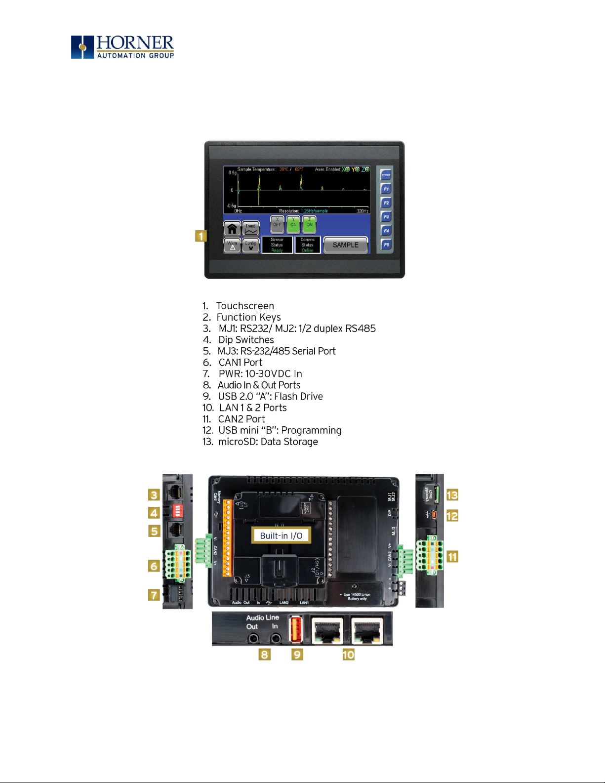
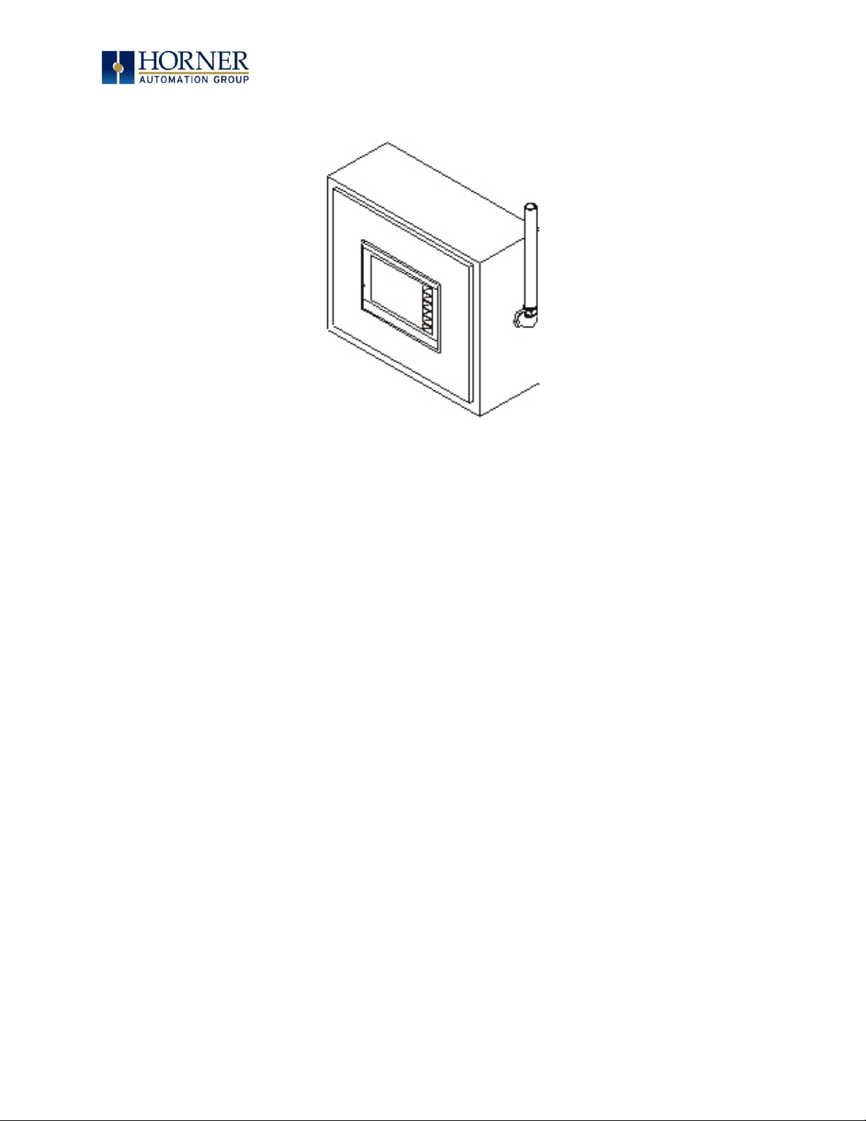
2.1 Visual Overview of XL7 OCS
Figure 2.1 – Overview of the XL7
Page 12

MAN0974-09-EN_XL7_UserManual
March 4th, 2019 Page 12 | 185
2.1.1 Where to Find Information about the XL7 OCS
a. Datasheet - The datasheet is the first document to refer to for key information
related to specific XL7 OCS models. The datasheets for all XL7 OCS models are
available on the Horner websites and contain pin-outs, jumper settings and
other model specific information.
Table 2.1 – Datasheet Manual Numbers
Model 0
MAN1161
Model 2
MAN1162
Model 3
MAN1163
Model 4
MAN1164
Model 5
MAN1165
Model 6
MAN1166
b. User Manual -This manual provides general information that is common to XL7 OCS
models and can be downloaded from our web. Visit the Horner website to obtain user
documentation and updates.
North America https://hornerautomation.com
Europe http://www.horner-apg.com
2.1.2 Four main types of information are covered in this manual
a) Safety and Installation guidelines / instructions (Mechanical and Electrical)
b) Descriptions of hardware features (Serial ports, Removable Media, Communication
Options, etc.)
c) Configuration and Use of the XL7 OCS
d) Maintenance and Support
2.1.3 Manual Index
Major topics of interest may be found in the Index towards the end of this manual.
2.1.4 Table of Figures
Location of important drawing, illustrations (etc.) may be found in the Table of Figures.
Page 13
MAN0974-09-EN_XL7_UserManual
March 4th, 2019 Page 13 | 185
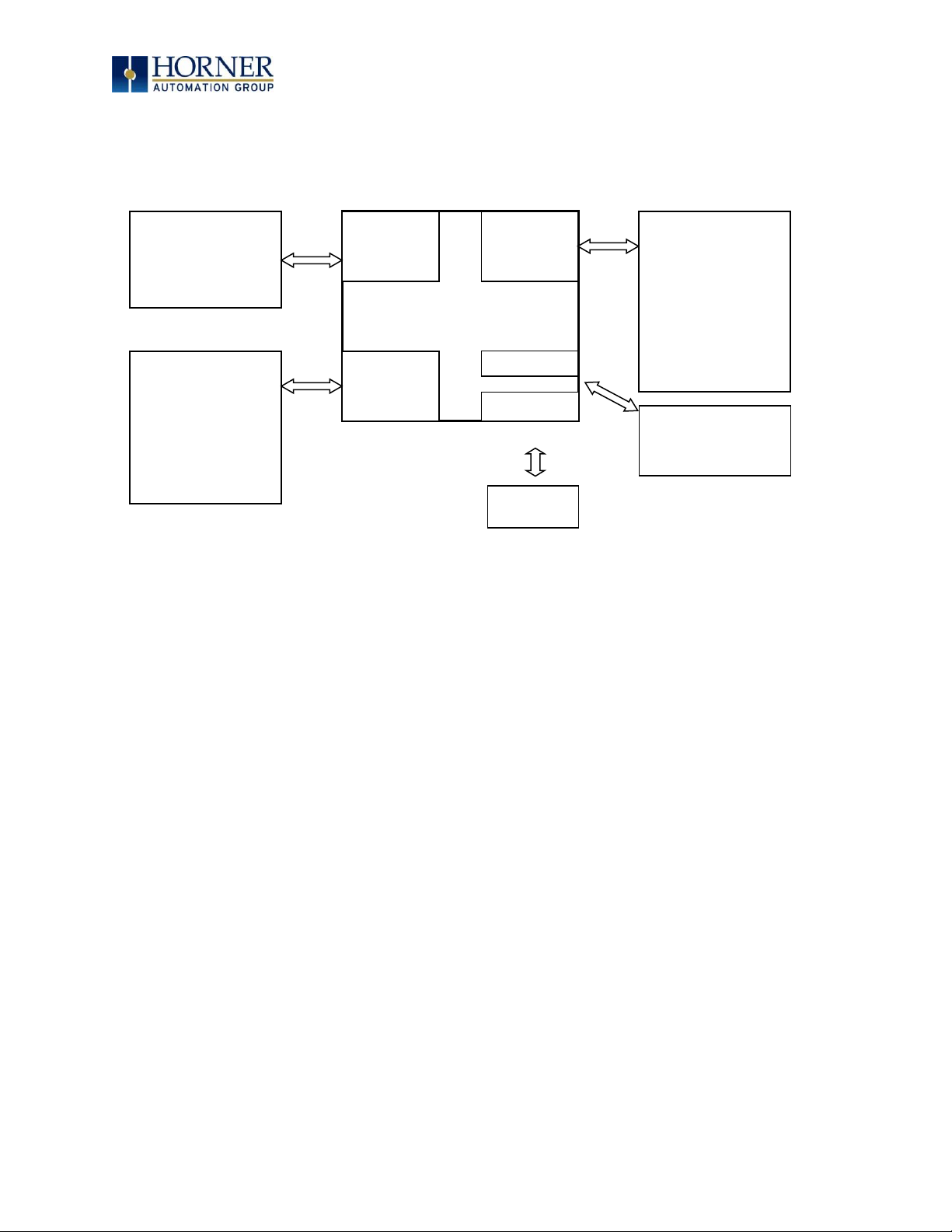
2.2 Connectivity to the XL7 OCS
The XL7 OCS has excellent capabilities for connecting to a variety of devices. The diagram
below shows some examples of devices that can be used with the XL7 OCS.
Figure 2.2 – Visual Overview of Types of Devices that can be connected to XL7 OCS
CAN
Serial
I/O
XL7 OCS
Other OCS Devices
Drives
PLCs
Bar Code Readers
Printers
SCADA
OPC Servers
Serial I/O
Sensors
Indicators
Alarms
Encoders
Pumps
Relays
Solenoids
Other OCS Devices
Smart Stix I/O
RCX116 I/O Base
OPC Server
Ethernet
Cscape
OPC Server
Modbus TCP Devices
USB
Flash Drive
Cscape
Page 14

MAN0974-09-EN_XL7_UserManual
March 4th, 2019 Page 14 | 185
2.3 Features of XL7 OCS
The XL7 OCS are all-in-one industrial control devices. They combine control, user interface,
I/O and networking into a single, integrated package. Unique features of the XL7 OCS include:
- Bright, 65,536 color graphical touch sensing LCD display in all models of XL7.
- Display of complex graphical objects including trends, gauges, meters and animations.
- High performance graphic processing.
- Advanced control capabilities including floating point, multiple auto-tuning PID loops
and string handling capabilities.
- Removable media for 32GB of storage of programs, data logging or screen captures.
- CsCAN networking port for communication with remote I/O, other controllers or PCs.
- High speed USB port for communication with PCs and programming of controller.
- Configurable serial protocols for communication to drives, PLCs, or other serial
peripherals.
- Full featured, built-in I/O including high resolution analog, thermocouple, RTD, high
speed counters, PWM outputs and relays (depending upon the XL7 OCS model used).
- Advanced high speed I/O capabilities.
- Cscape programming software that allows all aspects of the XL7 OCS to be programmed
and configured from one integrated application.
- Optional communication add-on modules.
- On board Ethernet port (10/100Mbps) for Cscape programming and application defined
communication, with Auto MDI/MDI-X.
Page 15
MAN0974-09-EN_XL7_UserManual
March 4th, 2019 Page 15 | 185
2.4 Accessories
Please visit the Horner Control Accessories website for communication, programming, and I/O
accessories.
North America http://hornerautomation.com/product-category/home/control-accessories/
Europe http://horner-apg.com/en/products.aspx
2.5 Useful Documents and References
Visit our website to obtain user documentation, supplemental documents, certificates, and
other documentation.
North America https://hornerautomation.com
Europe http://www.horner-apg.com
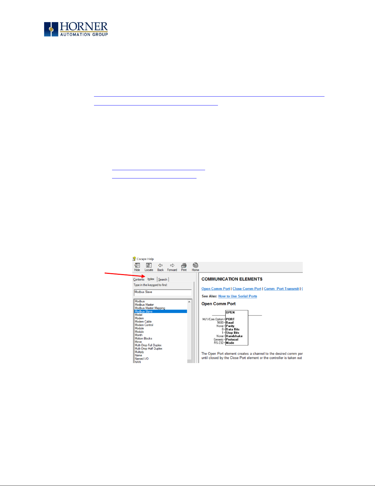
2.6 Opening Cscape Help File
After opening the Cscape Help file, either use the Contest, Index or Search tabs to located
information. The Cscape Help file has more information than the scope of this user manual.
Select “Index” tab.
Page 16

MAN0974-09-EN_XL7_UserManual
March 4th, 2019 Page 16 | 185
CHAPTER 3: MECHANICAL INSTALLATION
NOTE: The datasheet is the first document to refer to for model-specific information related
to XL7 OCS models such as pin-outs, jumper settings, and other key installation information.
Visit the Horner websites to obtain datasheets, user documentation, and updates.
North America https://hornerautomation.com
Europe http://www.horner-apg.com
3.1 Overview
The mechanical installation greatly affects the operation, safety and appearance of the
system. Information is provided to mechanically install the unit such as cut-out sizes,
mounting procedures and other recommendations for the proper mechanical installation of
the unit.
3.2 Mounting Requirements
3.2.1 Mounting Procedures (Installed in a Panel Door)
Figure 3.1 – Panel Mounting of an XL7 Series OCS
Page 17

MAN0974-09-EN_XL7_UserManual
March 4th, 2019 Page 17 | 185
Once the panel design has been completed using the criteria and suggestions in the following
sections, use the following steps to panel mount the XL7 OCS.
1. Remove all connectors from the XL7 OCS unit.
2. Make sure the gasket is installed on the XL7 OCS and is free from dust and debris.
Check that the corners of the gasket are secure.
3. Pass the unit through the panel.
4. Insert each of the four (4) mounting clips into the slots in the XL7 OCS case. One clip
should be installed on each corner. Lightly tighten each screw so the clip is held in
place.
5. Tighten the screws on the clips such that the gasket is compressed against the panel.
Recommended torque is 7-10 in-lbs (0.8-1.13 Nm).
3.3 Mounting Orientation
3.3.1 XL7 OCS Mounting Clip
Figure 3.2 – XL7 OCS with Mounting Clips
Slots for mounting clips
Page 18
MAN0974-09-EN_XL7_UserManual
March 4th, 2019 Page 18 | 185
3.3.2 XL7 OCS Mounting Orientation
Figure 3.3 – Orientation of XL7 OCS
NOTE: There are no orientation restrictions on the XL7 OCS. However, the above orientation
provides for optimum readability of the screen and ease of use of the keypad.
Page 19
MAN0974-09-EN_XL7_UserManual
March 4th, 2019 Page 19 | 185
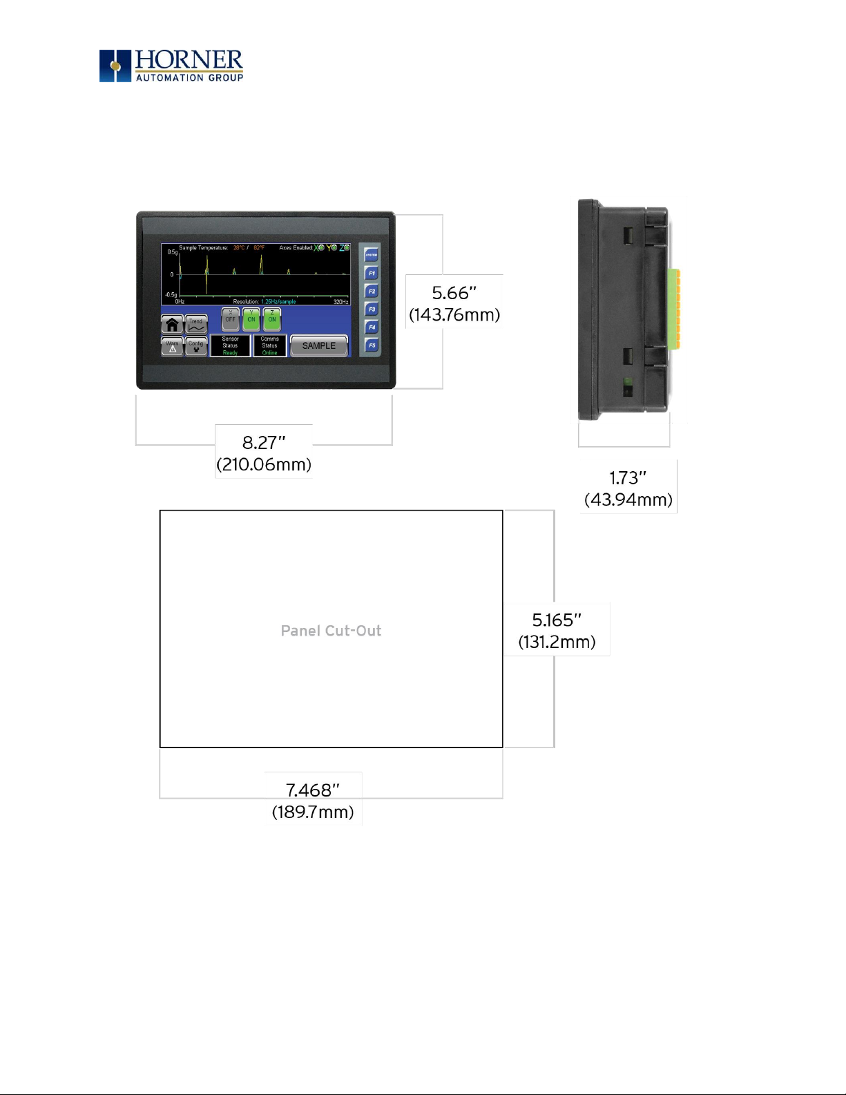
3.4 Panel Cut-Out
For installations requiring NEMA 4X liquid and dust protection the panel cutout should be cut
with a tolerance of +/- 0.005” (0.1mm).
Figure 3.5 – XL7 OCS Dimensions
Page 20

MAN0974-09-EN_XL7_UserManual
March 4th, 2019 Page 20 | 185
3.5 Factors Affecting Panel Layout Design and Clearances
The designer of a panel layout needs to assess the requirements of a particular system and to
consider the following design factors
.
3.5.1 Clearance / Adequate Space
Install devices to allow sufficient clearance to open and close the panel door.
Table 3.1 – Minimum Clearance Requirements for Panel Box and Door
Minimum Distance between
base of device and sides of cabinet
2” (50.80mm)
Minimum Distance between
base of device and wiring ducts
1.5” (38.10mm)
If more than one device installed in panel
box (or on door): Minimum Distance
between bases of each device
4” (101.60mm) between bases of each device
When door is closed:
Minimum distance between device and
closed door
(Be sure to allow enough
depth for the OCS.)
2” (50.80mm)
3.5.2 Grounding
Panel box: The panel box must be properly connected to earth ground to provide a good
common ground reference.
Panel door: Tie a low impedance ground strap between the panel box and the panel door to
ensure that they have the same ground reference.
3.5.3 Temperature / Ventilation
Ensure that the panel layout design allows for adequate ventilation and maintains the specified
ambient temperature range. Consider the impact on the design of the panel layout if operating
at the extreme ends of the ambient temperature range. For example, if it is determined that a
cooling device is required, allow adequate space and clearances for the device in the panel box
or on the panel door.
WARNING: It is important to follow the requirements of the panel manufacturer
and to follow all applicable electrical codes and standards.
WARNING: Be sure to meet the ground requirements of the panel manufacturer and meet
applicable electrical codes and standards.
Page 21

MAN0974-09-EN_XL7_UserManual
March 4th, 2019 Page 21 | 185
3.5.4 Orientation
When panel-mounted, there are no orientation restrictions on the XL7 OCS.
3.5.5 Noise
Consider the impact on the panel layout design and clearance requirements if noise
suppression devices are needed. Be sure to maintain an adequate distance between the XL7
OCS and noisy devices such as relays, motor starters, etc.
For details on output protection, especially when using contactors, solenoids, etc., see
MAN0962.
3.5.6 Shock and Vibration
The XL7 OCS has been designed to operate in typical industrial environments that may inflict
some shock and vibration on the unit. For applications that may inflict excessive shock and
vibration please use proper dampening techniques or relocate the XL7 OCS to a location that
minimizes shock and/or vibration.
3.5.7 Panel Layout Design and Clearance Checklist
The following list provides highlights of panel layout design factors:
Meets the electrical code and applicable standards for proper grounding, etc.?
Meets the panel manufacturer’s requirements for grounding, etc.?
Is the panel box properly connected to earth ground? Is the panel door properly
grounded? Has the appropriate procedure been followed to properly ground the
devices in the panel box and on the panel door?
Are minimum clearance requirements met? Can the panel door be easily opened
and closed? Is there adequate space between device bases as well as the sides of
the panel and wiring ducts?
Is the panel box deep enough to accommodate the XL7 OCS?
Is there adequate ventilation? Is the ambient temperature range maintained? Are
cooling or heating devices required?
Are noise suppression devices or isolation transformers required? Is there
adequate distance between the base of the XL7 OCS and noisy devices such as
relays or motor starters? Ensure that power and signal wires are not routed in the
same conduit.
Are there other requirements that impact the particular system, which need to be
considered?
Page 22

MAN0974-09-EN_XL7_UserManual
March 4th, 2019 Page 22 | 185
CHAPTER 4: ELECTRICAL INSTALLATION
NOTE: The datasheets are the first documents to refer to for model-specific information
related to XL7 OCS models such as pin-outs, jumper settings, and other key installation
information. Visit the Horner websites to obtain datasheets, user documentation, and updates.
North America https://hornerautomation.com
Europe http://www.horner-apg.com
4.1 Grounding Definition
Ground: The term ground is defined as a conductive connection between a circuit or piece of
equipment and the earth. Grounds are fundamentally used to protect an application from harmful
interference causing either physical damage such as by lightning or voltage transients or from
circuit disruption often caused by radio frequency interference (RFI). Grounding is also for the
safety of the user.
4.2 Ground Specifications
Ideally, a ground resistance measurement from equipment to earth ground is 0Ω. In reality, it
typically is higher. The U.S. National Electrical Code (NEC) states the resistance to ground shall
not exceed 25Ω. Horner APG recommends less than 15Ω resistance from our equipment to
ground. Resistance greater than 25Ω can cause undesirable or harmful interference to the
device.
Page 23
MAN0974-09-EN_XL7_UserManual
March 4th, 2019 Page 23 | 185
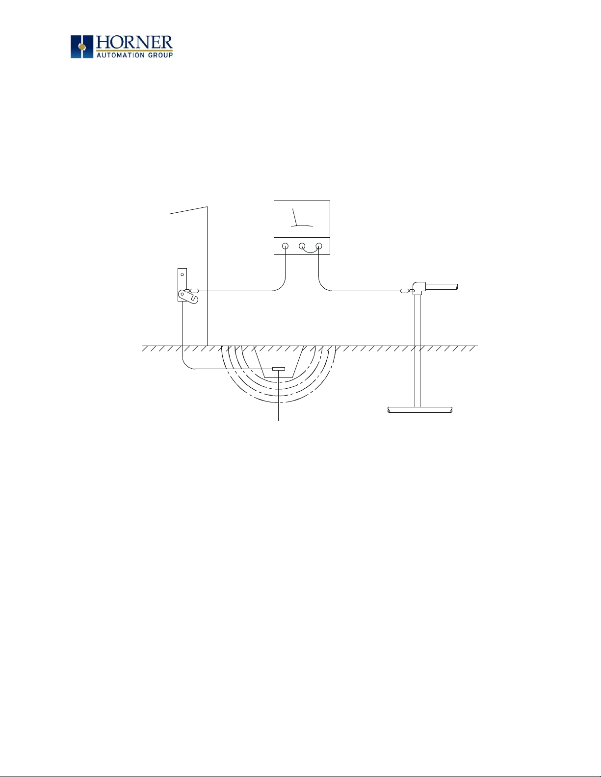
4.3 How to Test for Good Ground
In order to test ground resistance, a Ground Resistance Tester must be used. A typical Ground
Resistance Meter Kit contains a meter, two or three wire leads, and two ground rods. Instructions
are supplied for either a two-point or three-point ground test.
Figure 4.1 – Two-Point Ground Connection Test
METAL WATER PIPE OR
OTHER GOOD GROUND
GROUND ROD
GROUND
DISCONNECTED
FROM SERVICE
GROUND RESISTANCE METER
Page 24
MAN0974-09-EN_XL7_UserManual
March 4th, 2019 Page 24 | 185
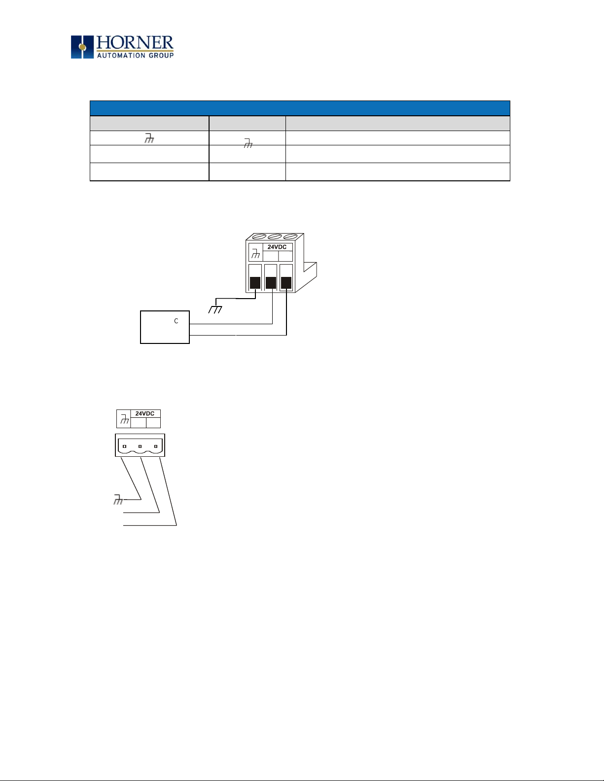
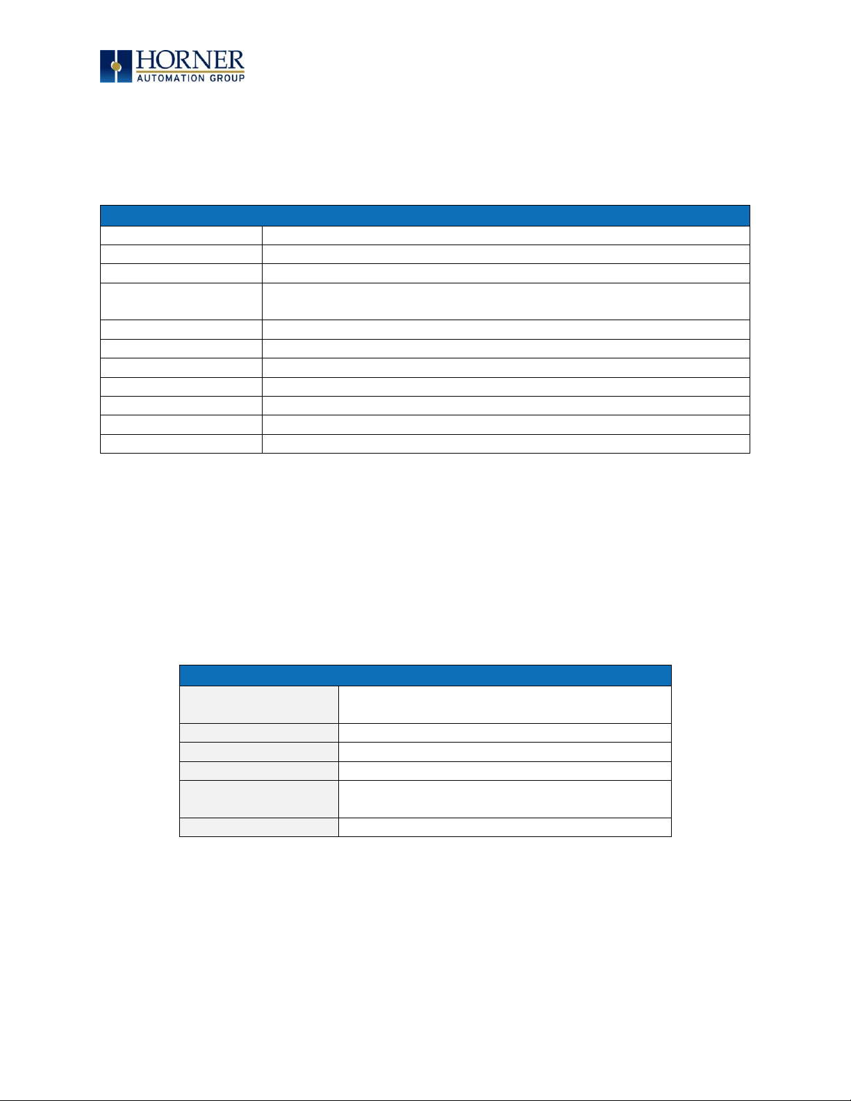
4.4 Primary Power Port
Table 4.1 – Primary Power Port Pins
PIN
Signal
Description
Frame Ground
-
0V
Input power supply ground
+
+24V
Input power supply positive voltage
Figure 4.1 – Power Connector (Primary Power Port)
Figure 4.2 – Primary Power Port
--
+
+
10-30VDC
supply
+
+
DC INPUT / FRAME
Solid/Standard Wire: 12-24 awg (2.5-0.2mm).
Strip Length: 0.28” (7mm).
Torque Rating: 4.5 – 7 in-lbs (0.50 – 0.78 N-m).
DC- is internally connected to I/O, but is isolated from
CAN-V.
A Class 2 power supply must be used.
Page 25

MAN0974-09-EN_XL7_UserManual
March 4th, 2019 Page 25 | 185
CHAPTER 5: SERIAL COMMUNICATIONS
5.1 Overview
All XL7 OCS models provide two independent serial ports, on the first 8-pin modular RJ45
connector, which is labeled MJ1/MJ2. The MJ1 serial port is RS232 while the MJ2 port is
RS485. By default, MJ1 can be connected to the COM port of a PC running Cscape, for OCS
programming. In addition, both MJ1 and MJ2 can be used for application-specific
communication, using a variety of standard data exchange protocols.
The second 8-pin modular RJ45 connector, which is labeled MJ3, provides a multiplexed serial
port, which can be configured for either RS232 or RS485. MJ3 can be optionally set for OCS
programming via the System Menu for connection to the COM port of a PC running Cscape.
5.2 Port Descriptions
The MJ1 serial port contains an RS232 interface with RTS/CTS handshaking. The MJ2 serial port
contains a half-duplex RS485 interface with no handshaking. The MJ3 serial port can be
configured as either RS232 or RS485. The MJ2 and MJ3 RS485 interfaces provide switchable
termination and bias resistors internally, which can be enabled/disabled with DIP switches.
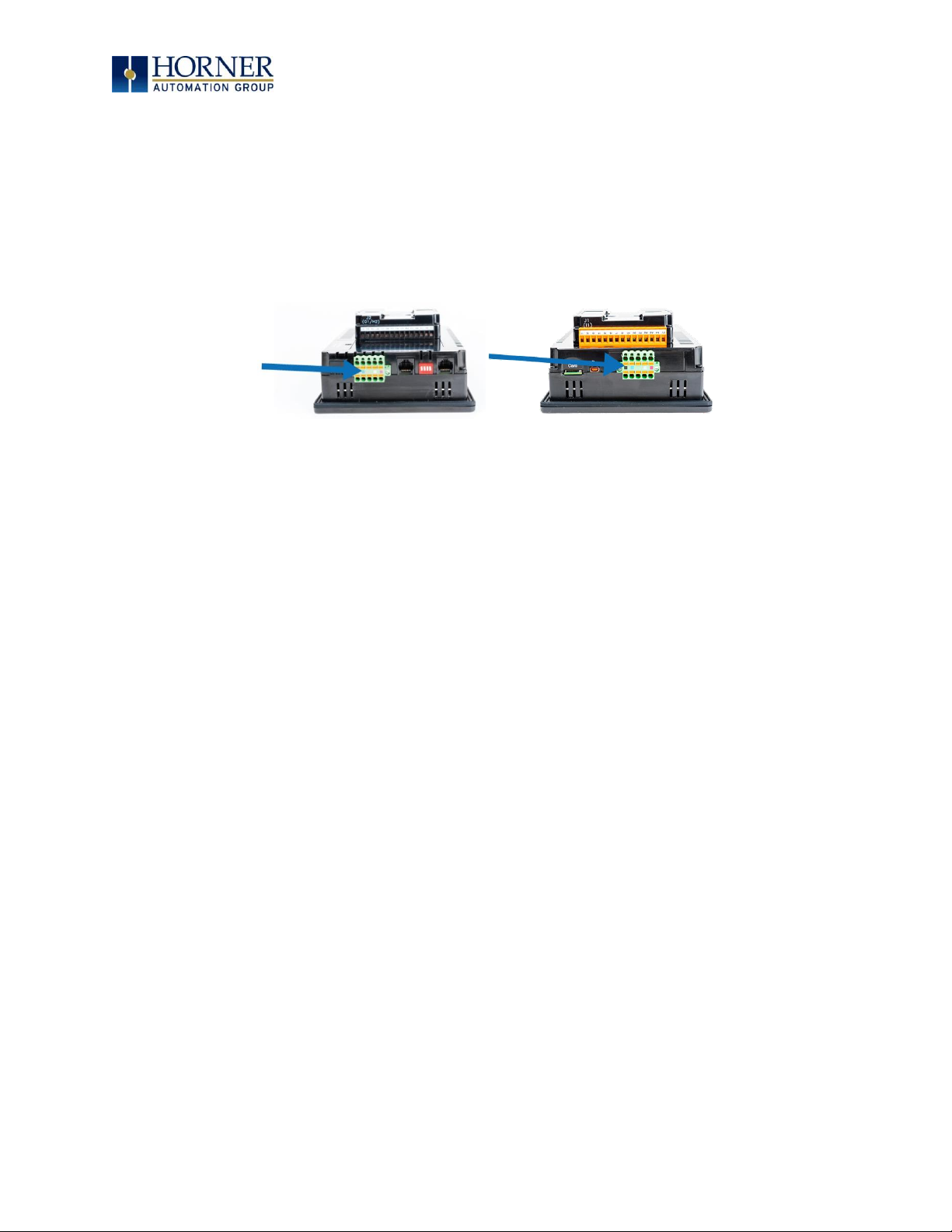
5.3 Wiring and Dip Switches
Figure 5.1 – Serial Ports
Page 26
MAN0974-09-EN_XL7_UserManual
March 4th, 2019 Page 26 | 185
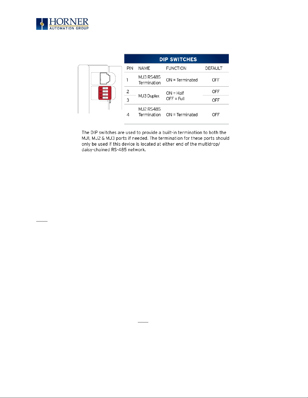
Figure 5.2 – Dip Switches
5.4 RS485 Termination
Proper RS485 termination minimizes signal reflections and improves reliability.
Both the MJ2 and MJ3 serial ports allow an internal termination resistor to be placed across
Pins 1 and 2 by DIP Switch Setting.
Only the two devices physically located at the endpoints of the RS485 network should be
terminated.
5.5 RS485 Biasing
RS485 biasing passively asserts a line-idle state when no device is actively transmitting, which
is useful for multi-drop RS485 networking.
Both the MJ2 and MJ3 serial ports allow internal bias resistors to be switched in, pulling pin 1
up to 3.3 V and pulling Pin 2 down to ground. The Set Serial Ports item in the System Menu
can be used to enable RS485 biasing. Also, an application graphics screen that writes to
%SR164 can do the same thing. Setting %SR164.1 enables MJ2 biasing and setting %SR164.2
enables MJ3 biasing.
If biasing is used, it should be enabled in only one of the devices attached to the RS485
network.
Page 27

MAN0974-09-EN_XL7_UserManual
March 4th, 2019 Page 27 | 185
5.6 Cscape Programming via Serial Port
The XL7 OCS MJ1 and MJ3 serial ports support CsCAN Programming Protocol. If a PC COM
port is connected to the XL7 OCS MJ1 or MJ3 serial port, Cscape can access the XL7 OCS for
programming and monitoring. Programming can also be done via the CAN port, USB A port, or
Ethernet.
5.7 Ladder-Controlled Serial Communication
Using Serial Communication function blocks, MJ1, MJ2, and MJ3 serial ports support Generic
Modbus Master and Modbus Slave Protocols. In addition, external modems can be connected
and accessed using Init, Dial and Answer Modem function blocks.
5.8 Configuration via Mini-B USB
NOTE: The unit must be connected via the mini-USB port to the PC or laptop.
It is possible to load the program and monitor data via the Mini-B USB. To load via Mini-B USB,
configure the communications port in Cscape as follows:
Select Tools from the toolbar → Application Settings → Communications → USB button
It is possible to download or upload and use the data monitoring functions once connected.
NOTE: It is advisable to use an isolated USB cable between the PC or laptop and the EXL6 when
third party devices are connected to the EXL6 to avoid damage to the PC or laptop and/or the
EXL6.
Page 28
MAN0974-09-EN_XL7_UserManual
March 4th, 2019 Page 28 | 185
CHAPTER 6: CAN COMMUNICATIONS
NOTE: For additional CAN information, refer to the CAN Networks manual (MAN0799) on the
Horner websites.
6.1 Overview
All XL7 OCS models provide two CAN network ports, which are implemented with 5-pin
connectors. The connectors are labeled CAN1 and CAN2.
Figure 6.1 – CAN1 & CAN2 Connector Locations
The CAN1 port allows the XL7 OCS to exchange global data with other OCS/RCS controllers and
to access remote Network I/O devices (SmartStix, Smart Blocks and Smart Rail Modules).
The CAN1 port also supports pass-through communications for programming multiple OCS
controllers over the CsCAN network.
CAN2 port supports CsCAN, CANopen, J1939 and DeviceNet Master (layer 3 as a selectable
option – one only).
6.2 Port Description
The XL7 OCS CAN ports implement the ISO 11898-2 physical layer and the CAN 2.0 A data link
layer standards. Also, since the CAN ports are powered by an internal isolated power supply,
external CAN power is not required.
NOTE: The CAN ports do not supply power to the network.
CAN1
CAN2
Page 29
MAN0974-09-EN_XL7_UserManual
March 4th, 2019 Page 29 | 185
6.3 CAN Port Wiring
Figure 6.2 – CAN1 / CAN2 Port Pins
6.4 Cscape Programming via CAN
The CAN1 port supports CsCAN Programming Protocol. If a PC has a CAN interface installed
(via PCI card or USB), and the PC CAN port is connected to the XL7 OCS CAN1 port, Cscape
can access the XL7 OCS for programming and monitoring.
In addition, the XL7 OCS supports single-point-programming of all XL7 OCS and other
OCS/RCS devices that are connected to the CAN1 port network. If the PC COM port is
connected to the XL7 OCS MJ1 serial port, the XL7 OCS can act as a pass-through gateway
allowing Cscape to access all XL7 OCS and OCS/RCS devices that are attached to the CAN1
port network.
6.5 Ladder-Controlled CAN Communication
Using Put and Get Network Words function blocks, the CAN 1 port can exchange digital and
analog global data with other XL7 OCS or OCS/RCS devices (nodes) attached to the CAN1 port
network.
In addition, Put and Get Network Heartbeat function blocks allow nodes on the CAN 1 port
network to regularly announce their presence and to detect the presence (or absence) of other
nodes on the network.
6.6 Using CAN for I/O Expansion (Network I/O)
Connecting Network I/O devices (SmartStix, SmartBlock, SmartMod or SmartRail) to the XL7
OCS CAN1 or CAN2 port, allows the XL7 OCS I/O to be economically expanded and distributed.
A variety of modules are available for this purpose.
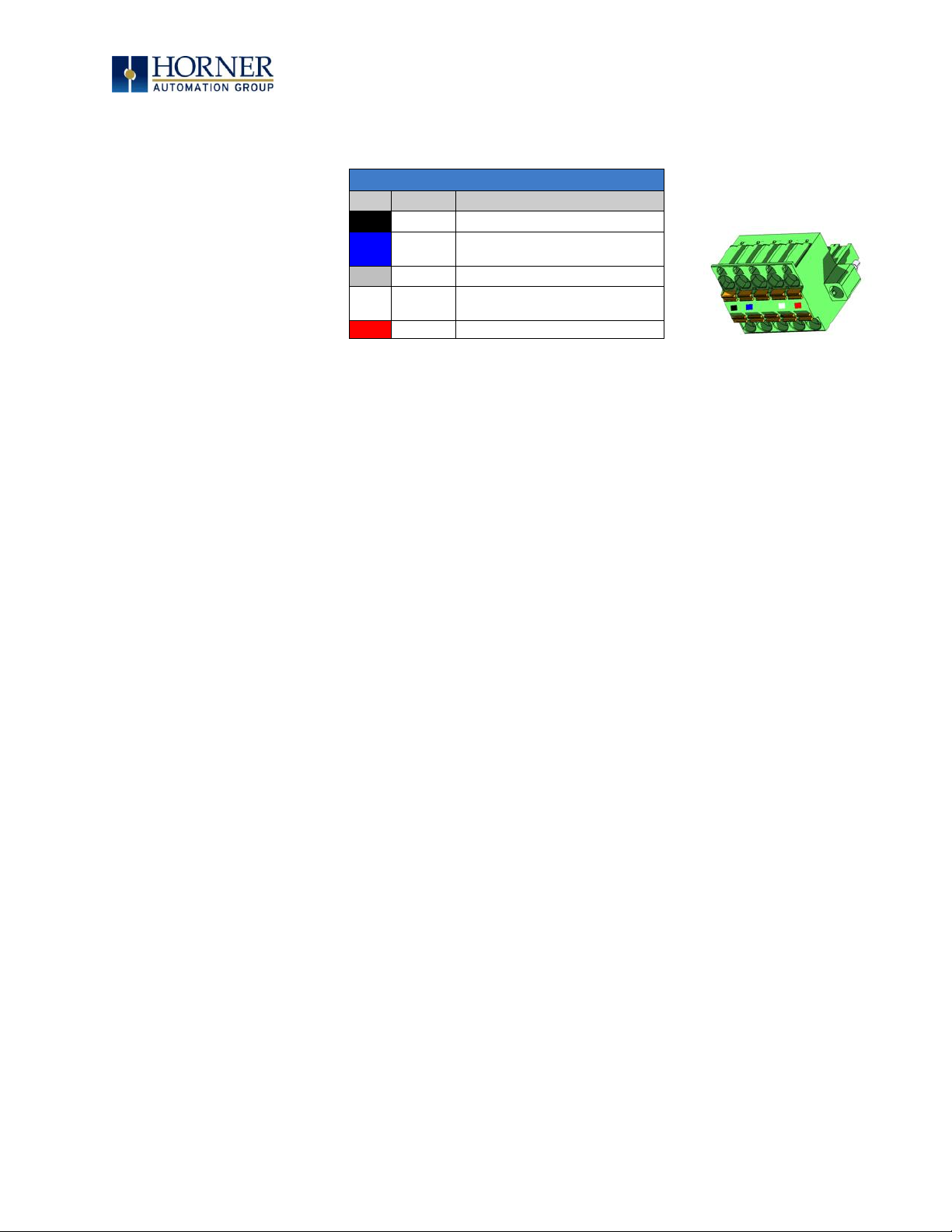
CAN1 & CAN2 Port Pins
Pin
Signal
Signal Description
1
V-
Power - Black
2
CN_L
CAN Data
Low - Blue
3
SHLD
Shield – No color
4
CN_H
CAN Data
High - White
5
V+
Power + Red
CAN Connector
Use the CAN Connector
when using CsCAN or other
CAN network.
Torque rating 4.5 – 7 in-lbs
(0.50 – 0.78 N-m)
Page 30
MAN0974-09-EN_XL7_UserManual
March 4th, 2019 Page 30 | 185
CHAPTER 7: ETHERNET COMMUNICATION
7.1 Ethernet Module Protocols and Features
The following table describes the Ethernet Module Protocols and features supported by XL7.
Table 7.1 – Ethernet Module Protocols & Features
Protocol / Feature
Protocol / Feature Description
ICMP (Ping)
Internet Control Message Protocol
EGD
Ethernet Global Data
SRTP (Slave 90-30
Service Request)
Service Request Transfer Protocol
CsCAN TCP Server
Horner APG CsCAN over Ethernet (for Cscape to OCS programming)
Modbus Slave
Modbus over Ethernet
Ethernet / IP
ODVA CIP over Ethernet
FTP (File Server)
File Transfer Protocol
ASCII over TCP/IP
ASCII Data over Ethernet
NTP (File Server)
Network Time Protocol (Obtain clock from web-based server)
HTTP (Web Server)
Hypertext Transfer Protocol (Web Server)
7.2 Ethernet System Requirements
Full Ethernet functionality requires:
- PC running Cscape Programming Software Version 9.3 SP6 or later (for configuration).
- XL7 controller with onboard Ethernet port.
7.3 Ethernet Module Specifications
Table 7.2 – Ethernet Module Specifications
Speeds
10 BaseT Ethernet (10Mbps)
100 BaseTx Fast Ethernet (100Mbps)
Modes
Half or Full Duplex
Auto-Negotiation
Both 10/100Mbps and Half/Full Duplex
Connector Type
Shielded RJ-45
Cable Type
(Recommended)
CAT5 (or better) UTP
Port
Auto MDI/MDI-X (Auto Crossover)
Page 31

MAN0974-09-EN_XL7_UserManual
March 4th, 2019 Page 31 | 185
7.4 Ethernet Module Configuration
NOTE: The following configuration is required for all applications regardless of the protocols
used. Additional configuration procedures must be performed for each protocol used.
To configure the Ethernet Module, use Cscape Programming Software to perform the following
steps
1. On the main Cscape screen, select the Controller → Hardware Configuration sub-
menu to open the Hardware Configuration dialog (Figure 7.1).
2. If configuring a different OCS Model than the one shown in the Hardware
Configuration dialog, click on the topmost Config button, select the desired OCS
Model, and then click OK.
Figure 7.1 – Hardware Configuration Dialog
Page 32

MAN0974-09-EN_XL7_UserManual
March 4th, 2019 Page 32 | 185
3. Click the Config button to the right of LAN1 for LAN 1 or LAN2 for LAN2, revealing the
Ethernet Module Configuration dialog as shown in Figure 7.2
Figure 7.2 – Ethernet Module Configuration
Configure the Ethernet Module parameters as follows:
IP Address: Enter the static IP Address for the Ethernet Module being configured.
NOTE: IP Addresses are entered as four numbers, each ranging from 0 to 255. These
four numbers are called octets and they are always separated by decimal points.
Net Mask: Enter the Net Mask (sometimes called Subnet Mask) being used by all nodes on the
local network. Typical local networks use Class C IP Addresses, in which case the low octet
(rightmost number) is used to uniquely identify each node on the local network. In this case,
the default Net Mask value of 255.255.255.0 should be used.
Gateway: Enter the IP Address of a Gateway Server on the local network that allows for
communication outside of the local network. To prevent the Ethernet Module from
communicating outside the local network, set the Default Gateway IP Address to 0.0.0.0 (the
default setting).
Status Register: Enter an OCS Register reference (such as %R100) to indicate which 16-bit OCS
register will have the Ethernet Status word written to it. Table 7.3 shows how this register value
is formatted and explains the meaning of each bit in the Status Word.
Page 33

MAN0974-09-EN_XL7_UserManual
March 4th, 2019 Page 33 | 185
Table 7.3 - Ethernet Status Word Register Format
High Byte
Low Byte
Bit
16
Bit
15
Bit
14
Bit
13
Bit
12
Bit
11
Bit
10
Bit 9 Bit 8 Bit 7 Bit 6 Bit 5 Bit 4 Bit 3 Bit 2 Bit
1
0 0 Dup
Spd 0 Rx
Tx
Link
TCP Connections
Status Bit(s)
Status Indication
Status Values
Minimum
Maximum 0 Reserved
Always 0
Dup
Link Duplex (Auto-Negotiated)
0 = Half
Duplex
1 = Full
Duplex
Spd
Link Speed (Auto-Negotiated)
0 = 10MHz
1 = 100MHz
Rx
Receive State
0 = Inactive
1 = Active
Tx
Transmit State
0 = Inactive
1 = Active
Link
Link State
0 = Down
1 = Up
TCP Connections
Total Number of Active TCP
Connections
(CsCAN, SRTP, Modbus, EIP, FTP, HTTP)
0
40
Version Register – Enter an OCS Register reference (such as %R101) to indicate which 16-bit OCS
register will have the Ethernet Firmware Version written to it. The value stored in the Version
Register is (Ethernet Firmware Version * 100). For example, for Ethernet Firmware Version 4.30,
the Version register will contain 430.
Get Settings From – “Get settings from” allows the programmer to configure either the IP
Address, Net Mask, or Gateway for 2 functions: Configuration or Register
Configuration – The configuration for the IP Address, Net Mask, or the Gateway will be assigned
using the value in the Default Settings in this window.
Register – The configuration for the IP Address, Net Mask, or the Gateway will be assigned using
the values in the registers assigned.
NOTE: The low octet of the IP Address can be replaced with the unit’s CAN Network ID, by
checking the Use CAN ID for last Octet checkbox.
Page 34

MAN0974-09-EN_XL7_UserManual
March 4th, 2019 Page 34 | 185
7.5 Ethernet Configuration – IP Parameters
For primary operation, the IP address, Net Mask, and Gateway should be set in the LAN config
of the Cscape Hardware Configuration. There are options to get IP parameters from the LAN
Config or to get parameters from registers. It is possible to set the Ethernet IP parameters
from the OCS System Menu, but only as a temporary measure. The following points on IP
parameter configuration should be considered.
• IP Parameters in Non-Volatile RAM: The IP parameters of the Cscape LAN Config are
written to non-volatile RAM on power down. IP parameter settings made in the System
Menu are not written to non-volatile RAM. Any IP parameters settings made in the
System Menu will be lost after cycling power to the unit. It will revert back to the last
downloaded Cscape LAN Config that was loaded into non-volatile RAM at power down.
• “Cscape LAN Config”/ “Get Settings from” Configuration: When ‘Get settings from’ is
set to Configuration, the IP parameters specified under ‘Default Settings’ is used after
downloading to the controller. The IP parameters are represented in System Menu /
Set Networks and can be edited. However, any edits made from System Menu / Set
Networks is not retained through a power cycle. After power cycle, the unit reverts to
the last downloaded Cscape LAN Config that was loaded into non-volatile RAM at
power down.
• “Cscape LAN Config” / “Get Settings from” Register: When ‘Get settings from’ is set to
Register, the IP parameters are retrieved from the OCS registers assigned in LAN
Config. Configured registers must be populated with the desired IP parameters.
The IP parameters are represented in System Menu / Set Networks.
The IP parameters cannot be edited from System Menu / Set Networks while the unit is
in run mode.
The IP parameters always follow the values in the registers unless the OCS unit is
placed in idle mode. Then the IP parameters can be edited in System Menu / Set
Networks. When the OCS is placed back into run mode, it reverts to the registers for IP
parameters.
7.6 Ethernet Module Protocol Configuration
The Protocol Support area contains a list of all the protocols supported by the platform being
configured. To activate a protocol, check its checkbox.
For protocols that require additional configuration, click on a listed protocol to select it and
then click the Configure Selected Protocol button. This will open a new dialog with
configuration options for the selected protocol.
For detailed information on individual protocol configuration refer latest version of ETN 300
Manual SUP0740.
Page 35

MAN0974-09-EN_XL7_UserManual
March 4th, 2019 Page 35 | 185
CHAPTER 8: DOWNLOADABLE COMMUNICATION
PROTOCOLS
8.1 Overview
Through loadable protocol device drivers, certain models of the OCS family can provide the
ability to exchange data with remote devices such as variable-frequency drives, PLCs, and
remote I/O devices. This feature greatly expands the OCS ’s control capability with negligible
effect on the OCS ’s ladder scan time.
Remote devices that communicate serially must do so under certain rules of data transfer
known as a protocol. Many device manufactures have created their own protocol for
communications with their device. For an OCS to communicate with a specific device, it must
be loaded with the corresponding serial communications protocol device driver that supports
that protocol.
A limited number of protocol device drivers are packaged with the Cscape distribution;
however, as more are developed, they will be made available as add-on packages. A device
driver is typically distributed as a Windows module, which contains the Configuration Menus,
Help Files and the Target Executable Driver Code. When updating device drivers, an install
routine loads the device driver to the Cscape directory structure and makes that driver
available to Cscape applications.
Once installed, the protocol device driver can be included as part of a Cscape application by
selecting it from a list of installed protocol device drivers and attaching it to the desired serial
port (Program > Protocol Config menu). Only one protocol device driver can be associated
with a serial port, though some OCS models support multiple protocols on a single Ethernet
port.
Once the protocol is selected for a specific port, that port must be configured to match the bit
transfer size and rate of the target device(s). This is configured under the Network Config
menu, which contains port specific information such as the basic serial port parameters (i.e.
baud rate, stop bits parity, retries, etc.). In addition to the serial port parameters, this menu
also contains the transaction scan update control configuration and any network level
protocol specific configuration.
Once the network is configured, each device on the serial communications network must be
configured. For some communications (i.e. RS232), the network can be limited to one device.
The devices are configured under the Device Config menu, which contains an arbitrary device
name, the device ID and optionally an OCS status register that contains any device fault
information.
Once each device(s) is configured, a Scan List of entries must be created which defines the
transfer of data between a local (OCS) register(s) and a remote device register(s). These
entries are created under the Data Mapping menu, which contains an OCS register, a target
device ID, a target device register address, the number of registers to transfer, and update
type.
Page 36
MAN0974-09-EN_XL7_UserManual
March 4th, 2019 Page 36 | 185
Each entry can be configured for one of two types of initiating a transaction: Polled and
Triggered. Polled type entries initiate a transaction with the remote device on every
transaction scan. Triggered type entries only initiate a transaction when a corresponding local
(OCS) binary trigger register is
set
. Once a triggered type transaction completes, the protocol
device driver resets the local (OCS) binary register to indicate completion. Refer to the Scan
List Section for more details on Polled and Triggered entries.
These basic types are also subdivided into Read or Write operations. For polled operations, a
Read operation only reads from a remote device. Likewise, a Read/Write operation
continuously reads from the remote device unless the target OCS register value changes from
one ladder scan to another. In this case, the new OCS value is written to the target device. For
triggered operations, only a Read or Write action is available.
When downloaded to the OCS, the Scan List is scanned sequentially to generate data
transactions with the remote device. This transaction scanning can be on a continual basis
(automatic) or controlled from ladder logic (manual) once a complex connection is
programmatically created (i.e., dialup modem). The specific transaction-scanning mode is
selected from the Network Config menu.
The following Horner Automation websites offer OCS Protocol Software Downloads.
North America http://hornerautomation.com/support-files/
Europe http://www.horner-apg.com/en/products/software/ocs-protocols.aspx
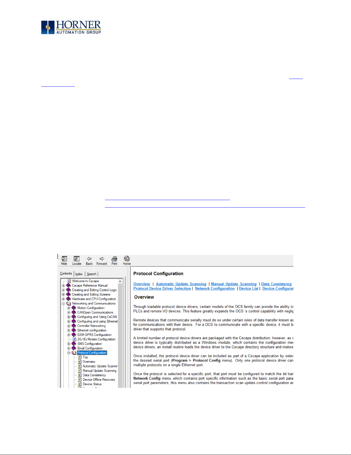
Please refer to the Cscape Help file for more information on Downloadable Protocols
Configuration. After opening the Cscape Help file, select Contents → Networking and
Communications → Protocol Configuration.
Page 37

MAN0974-09-EN_XL7_UserManual
March 4th, 2019 Page 37 | 185
8.2 Protocol Config
After opening Cscape, choose Program → Protocol Config, and select the port drop-down box
to select a protocol device driver. All protocol device drivers currently loaded in Cscape are
displayed in the dropdown selection. Some OCS models can be limited in the number of ports
or number of protocol device drivers that can be selected. Once a protocol is selected, the
Network, Devices, and Data (Scan List) must be configured through corresponding dialogs
accessible through the respective buttons (Network, Device, and Scan List.)
Figure 8.1 – Protocol Config Dialog
Three fields must be configured after a protocol is selected:
1. Network
2. Devices
3. Scan List
Page 38

MAN0974-09-EN_XL7_UserManual
March 4th, 2019 Page 38 | 185
8.3 Network Configuration
Network Configuration provides the required parameters to configure the network.
Each protocol is different and may not require all the Network Config field. Please
refer to the table below for the options in the Network Config field.
Page 39

MAN0974-09-EN_XL7_UserManual
March 4th, 2019 Page 39 | 185
Table 8.1 – Network Protocols
Baud Rate, Data Bits, Stop
Bits, Parity
These field define the bit level transfer over the serial port.
Handshake
None – No handshake lines are used
Multidrop Full – Rx remains active while Tx is occurring.
Multidrop Half – Rx is shut off while Tx is occurring.
Radio Modem – Wait for CTS acknowledgement before
transmitting (legacy radio modem support).
Protocol
If a driver supports multiple protocols, it is selected here,
(i.e. Modbus supports RTU or ANSI).
Mode
Specifies if port operates in RS232 or RS485 mode.
Retries
Specifies number of times a transaction is retried on a failed
response.
Timeout
Specifies the amount of time for a device to wait for a valid
response.
Update Scan
Automatic
Update Interval – Specifies the update interval
at which all the mapped entries are executed.
Reacquire Time – Specifies the amount of time
to wait before attempting communications with
an offline device.
Manual
Trigger – Specifies the binary register that a
single transaction scan of the Scan List.
ID Select – If an analog is specified in the field,
the ID Select filter is enabled.
Status Register
Specifies the starting OCS register of eight (8) consecutive
registers (4-32bit counters), which provide an indication of
the network health.
Scanner Address
Specifies the OCS’s device (network) ID if a master ID is
required by the protocol.
Protocol Help
Provides protocol specific help.
Page 40

MAN0974-09-EN_XL7_UserManual
March 4th, 2019 Page 40 | 185
8.4 Device List and Device Configuration
Device List
The Device List is reached from the Device button on the Protocol Config screen and provides
a list of the configured devices on the Network. Devices must be created and exist in this list
before corresponding Scan List entries can be created for this device. Typically, the number of
entries is limited to 64 devices.
Device Configuration
This configuration is reached from the Device List when adding or modifying an existing
device.
Page 41
MAN0974-09-EN_XL7_UserManual
March 4th, 2019 Page 41 | 185
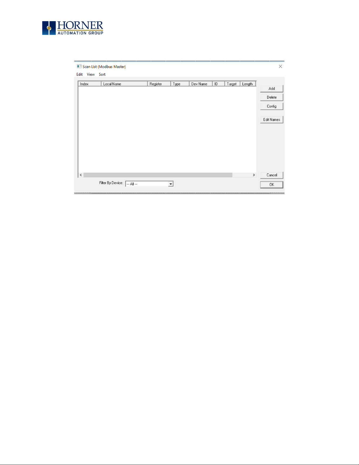
8.5 Scan List
This can be accessed from the Scan List button on the Protocol Config screen or the Mapping
button on the Device List screen and provides a Scan List of the Data Mapping entries. To
transfer data between the OCS and remote target, a Scan List must be created that defines
each transaction. Each mapping entry (transaction) contains the source and destination
registers, the number of consecutive registers transferred, the direction of the transfer and
what triggers the transfer. Typically, the number of entries is limited to 512.
NOTE: The order of the Scan List is the order in which the transactions occur. Sort functions
are provided to change the order of the list. Each entry also has an identifying index. If the
device status register is enabled and a transaction failure occurs, the status register indicates
the index number of the transaction that has failed.
Page 42

MAN0974-09-EN_XL7_UserManual
March 4th, 2019 Page 42 | 185
8.6 Data Mapping Configuration (Scan List Entry)
Update Type
This field specifies the direction and what triggers the transfer of data between the OCS and
target device for a mapping entry.
Polled Read
On every transaction scan, a read-only target device register(s) transaction occurs.
Polled Read/Write
On every transaction scan, a read target device register transaction occurs unless a local
register value has changed. The write transaction only updates those local registers that have
changed in value. If several non-consecutive local registers (contained in a single mapping
entry) change value between transaction scans, it takes several consecutive transaction scans
to write each changed register.
When the OCS is placed in RUN mode, the initial action for this mapping type is a read target
register transaction. This transaction initializes the local (OCS) register(s) to match that of the
remote device register(s). Thereafter, any change to the corresponding OCS register(s)
triggers a write operation to the remote device.
Page 43

MAN0974-09-EN_XL7_UserManual
March 4th, 2019 Page 43 | 185
Polled Read/Write/Init
On every transaction scan, a read target device register transaction occurs unless a local
register value has changed. The write transaction only updates those local registers that have
changed in value. If several non-consecutive local registers (contained in a single mapping
entry) change value between transaction scans, it takes several consecutive scans to write
each changed register.
When the OCS is placed in RUN mode, the initial action for this mapping type is a write target
register transaction. This transaction initializes the target device register(s) to match that of
the local (OCS) register(s). Thereafter, any change to the corresponding OCS register(s)
triggers a write operation to the remote device.
The initial write transaction does not occur until after the first logic scan of the OCS. This
allows registers to be initialized locally before Writing to the target device register(s).
Triggered Read
A read transaction is triggered by a high level on a separately designated OCS (binary) trigger
register. Once the read transaction is complete (or the device is offline), the OCS trigger
register is cleared by the OCS. This update type can be used for occasion data accesses such
as retrieving trend data.
NOTE: This operation increases the associated transaction scan time and can cause the
Update Interval Exceeded Counter to increment on a tightly adjusted update interval.
Triggered Write
A write transaction is triggered by a high level on a separately designated OCS (binary)
trigger register. Once the write transaction is complete (or the device is offline), the OCS
trigger register is cleared by OCS. This function can be used for occasion data accesses such
as sending recipe data.
NOTE: This operation increases the associated transaction scan time and can cause the
Update Interval Time Exceeded Counter to increment on a tightly adjusted update interval.
Page 44
MAN0974-09-EN_XL7_UserManual
March 4th, 2019 Page 44 | 185
CHAPTER 9: SYSTEM SETTINGS AND ADJUSTMENTS
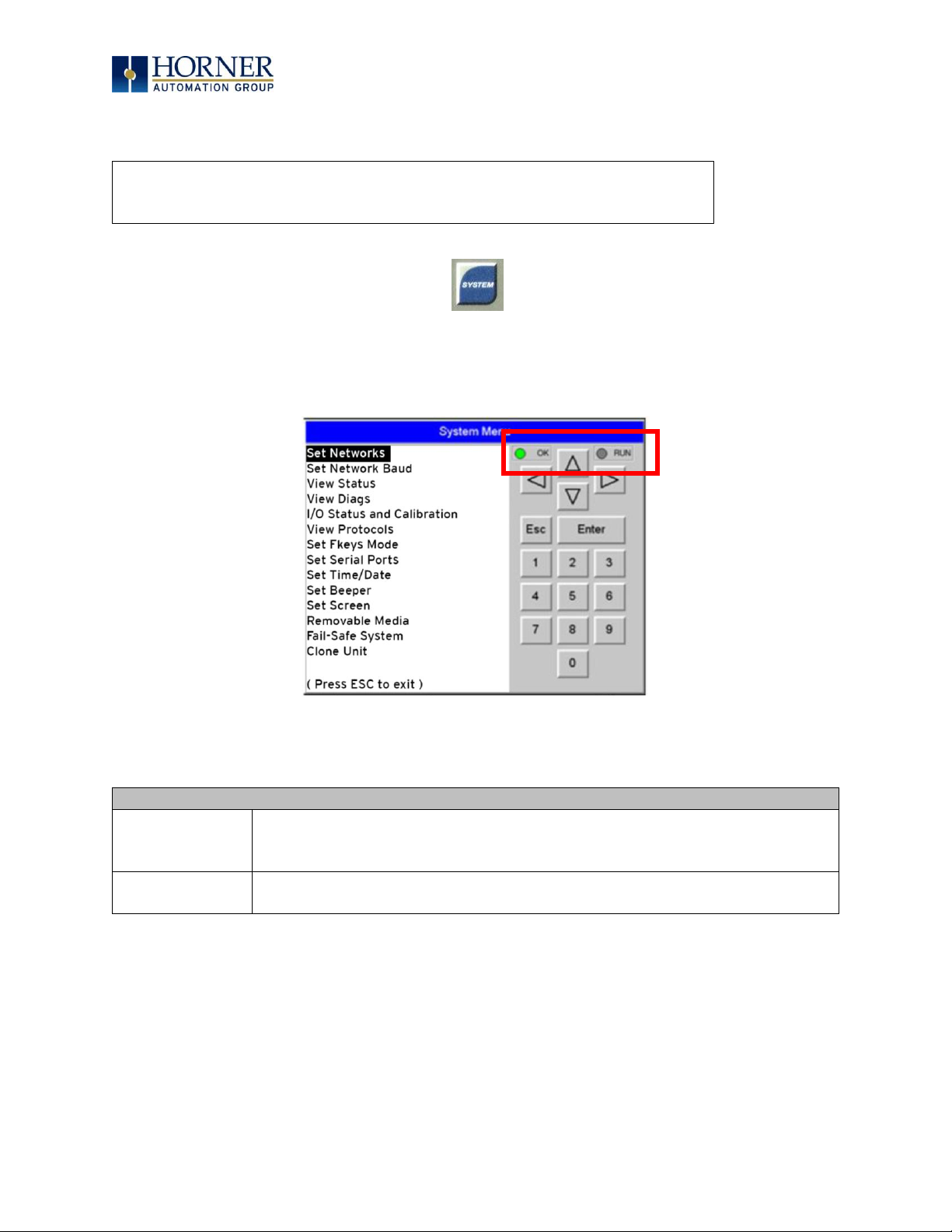
9.1 System Menu - Overview
The XL7 has a built-in System Menu, which lets the user view System Settings and makes
adjustments. To start the System Menu, press the SYSTEM key (or set %SR3 to 1), which will
display the Main Menu. Then use the and (Up Arrow or Down Arrow) keys to select a Main
Menu item and press Enter (Return Arrow) to display the item’s Sub-Menu.
Figure 9.1 – System Menu (XL7) Screenshot
Table 19.1 - OCS LEDs
RUN
• OFF indicates OCS is in IDLE/STOP mode.
• Flashing indicates DO / IO mode or RUN with no ladder program.
• ON indicates ladder code running.
OK
• OFF indicates one or more self-tests failed.
• ON indicates all self-tests passed.
See table below
for RUN and OK
LED information.
Press the upper right corner to bring out the function keys and SYSTEM
key in order to access the Main Menu.
Page 45

MAN0974-09-EN_XL7_UserManual
March 4th, 2019 Page 45 | 185
9.2 System Menu – Navigation and Editing
As mentioned above, the System Menu is started by pressing the System key on the XL7. Next
press ESC to exit the System Menu or use and to select an item and press Enter to
display the item’s Sub-Menu.
A Sub-Menu generally shows a list of System Settings and their values. After opening a SubMenu, if any of its System Settings are editable, the first System Setting that can be edited is
highlighted. If desired, the and keys can be used to select a different System Setting to be
edited.
At this point, either press ESC to exit the Sub-Menu (returning to the Main Menu) or press Enter
to edit the highlighted System Setting. If Enter is pressed, the System Setting’s value will be
highlighted, indicating that it is ready to be modified.
When modifying a System Setting’s value, use either the arrow keys ( → )
or the numeric keys, or the appropriate touch screen icons to select a new value.
The arrow keys are used to edit System Settings that have just a few possible values. Each time
the arrow key is pressed, a new possible value is displayed. When the desired value appears,
press the Enter key to save it; otherwise press the ESC key to cancel the edit.
The numeric keys are normally used to enter numeric System Settings.
In addition, to edit a single numeric digit, use the or → key to select the digit and then either
press a numeric key or use or to modify the digit. In any case, after entering the new desired
value, press the Enter key to save it; otherwise press the ESC key to cancel the edit.
Page 46
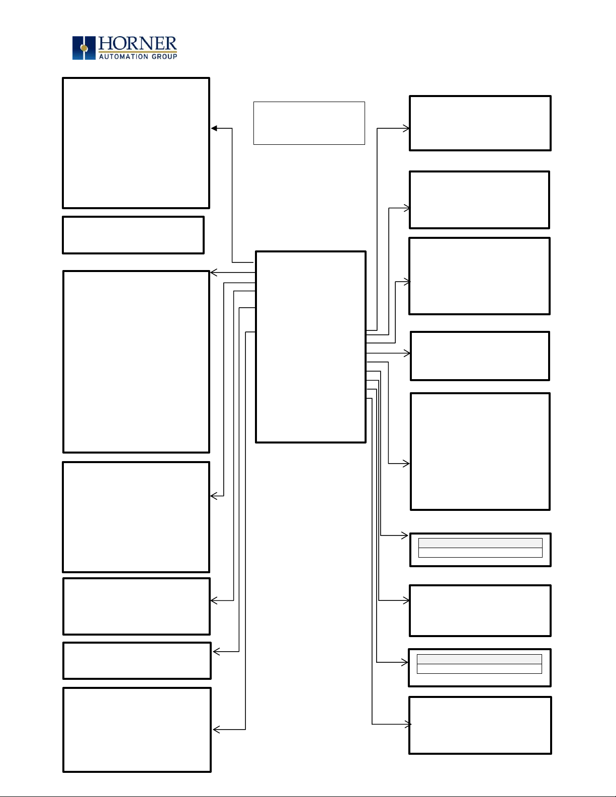
MAN0974-09-EN_XL7_UserManual
March 4th, 2019 Page 46 | 185
Figure 9.2 – System Menu
Sub-Menus
Set Networks
View Status
View Diags
View Battery
Status
View I/O Slots
View Protocols
Set Fkeys Mode
Set Serial Ports
Set Time/Date
Set Beeper
Set Screen
Removable Media
Fail-Safe System
Clone Unit
License Details
(Press ESC to
Exit)
Network Ok?
No
Network ID
1
CAN
Termination
No
MAC ID:
00:E0:C4:04:C7:
35
IP Address:
192.168.254.1
28
Network
Mask:
255.255.255.0
Gateway
0.0.0.0
NetM2:
255.255.255.0
GatW2
0.0.0.0
Model:
HE-X7R
Mode:
Run
Scan Rate(mS):
2.4
Lcl Net Use(%):
0.0
All Net Use(%:)
0.0
Ladder Size:
7724
Config Size:
648
Graphics Size:
76164
String Size:
18996
Bitmap Size:
1812850
Text Tbl Size:
152
Font Tbl Size:
130984
Protocol Size:
16
SMS File Size:
16
Firmware Rev:
14.15
BIOS Rev:
0.22
itRD Rev:
1.06
OS Ver:
2.6.35.44
Self-Test:
OK
Logic Error:
Ok
User Program:
Ok
User Graphics:
Ok
W-Dog Trips:
2
Net Errors:
0
Network State:
Ok
Network ID:
Ok
Dup Net ID:
Ok
Clock Error:
Ok
I/O System
Ok
Battery:
Ok
Slot 1: I/O: Xex02
Slot 2: I/O: Empty
Slot 3: I/O: ETN300
MJ1:
(None Loaded)
MJ2:
(None Loaded)
COM:
(None Loaded)
MJ3:
(None Loaded)
Fkeys:
Momentary
SYS-Fn enable:
Yes
( Use ↑↓ to adjust )
Dflt Pgm Port
MJ1-232
MJ2 RS485 Bias
No
MJ3 RS485 Bias
No
( Use ↑↓ to adjust )
Time:
14:58:03
Date:
08-Sep-2015
Day:
Tuesday
UTC/Daylight Savings Time
( Use ↑↓ to adjust )
( each field )
Beeper
enable:
No
( Use ↑↓ to adjust )
Server enable:
No
Timeout(min):
15
Popup Status:
Off
Update Time(mS):
5
Update time sets
the maximum time
used by graphics
in the logic scan.
Media Directory
Media Card Not Present
Backup/Restore Data
Enable AutoRun
Enable AutoLoad
(ESC to exit)
Clone Unit
Media Card Not Present
Sub-Menus
CPU Temperature (C) 57
Battery Voltage (mV) 3046
CPU Frequency (MHz) 996
MAX Temperature (C) 61
License Details
Server/ Users/ Pages/Data
Points/ Exp. Date/User
Logged In
XL7 System
Menu Map
Network Baud:
125 KB
( Use ↑↓ to adjust )
Page 47

MAN0974-09-EN_XL7_UserManual
March 4th, 2019 Page 47 | 185
9.3 System Menu – Details
The following sections describe each of the Sub-Menus in detail.
Set Networks
This sub menu allows setting for the CAN and Ethernet network to be viewed or changed.
CAN Ok?
Yes= CAN1 connected to a CAN network and functioning properly
No= Not ready to communicate on CAN network
CAN ID
1 to 253 = This node’s CsCAN Network ID; must be unique on network
CAN Baud
125kB = 125kBd CAN network
250kB = 250kBd CAN network
500kB = 500kBd CAN network
1MB = 1MBd CAN network
MAC ID
Displays the Ethernet MAC ID of the unit
IP
Displays the Ethernet IP address of the unit
NetM
Displays the Ethernet net mask of the unit
GatWy
Displays the Ethernet gateway of the unit
NOTE: The IP address, Net Mask and Gateway can be changed from the System Menu. This is
designed for commissioning or temporary field changes. The actual parameters are defined in
Cscape under the Ethernet configuration and are reverted to whenever the unit goes from idle
to run mode.
Page 48

MAN0974-09-EN_XL7_UserManual
March 4th, 2019 Page 48 | 185
View Status
The View Status Sub-Menu displays up to 19 System Settings. Only the OCS Mode System Setting is
editable.
Model
XW1yz= Model number of this XL7 OCS unit
1yz = indicates the installed I/O module
00 = no I/O module
OCS Mode
Idle = XL7 OCS is in Idle mode
DoIO = XL7 OCS is in Do I/O mode
Run = XL7 OCS is in Run mode
Scan Rate(mS)
0.0 = XL7 OCS is not in Run mode
0.1 to 999.9= Average number of mS for each ladder scan
OCS Net Use %
0.0 to 100.0 = CAN network bandwidth % used by this XL7 OCS node
All Net Use %
0.0 to 100.0 = CAN network bandwidth % used by all nodes
Ladder Size
x = Number of bytes in application ladder program
Config Size
x = Number of bytes in application I/O configuration
Graphics Size
x = Number of bytes in application graphic screens
String Size
x = Number of bytes in application string table
Bitmap Size
x = Number of bytes in application bitmaps
Text Tbl Size
x = Number of bytes in application text tables
Font Tbl Size
x = Number of bytes in application font tables
Protocol Size
x = Number of bytes in application downloaded protocols
SMS File Size
x = Number of bytes in application SMS protocol configuration
Firmware Rev
xx.yy = Current firmware version
OS Ver
a.b.cd.yz = Current Operating System version
FPGA Rev
x.y = Current FPGA version (High Speed IO Sub System)
InitRD Rev
x.yz = Bootloader version
Self-Test
Ok = All power-on self-tests passed
Fault = One or more power-on self-tests failed
Page 49

MAN0974-09-EN_XL7_UserManual
March 4th, 2019 Page 49 | 185
View Diags
The View Diags Sub-Menu displays up to 11 System Diagnostics, none of which are editable.
The first two System Diagnostics are critical. If either of these indicate a Fault condition, the
XL7 OCS will not enter or remain in Run mode, and the problem must be investigated and
corrected.
Logic Error:
Ok = All executed ladder instructions are legal for loaded firmware
Fault = A ladder instruction not supported by firmware was found
User Program:
Ok = Ladder program and I/O configuration loaded successfully
Fault = Ladder program or I/O configuration not loaded or load failed
The last nine System Diagnostics are informational. If any of these indicate a warning condition,
the XL7 OCS can still enter and remain in Run mode, but the problem should be investigated
and corrected.
User Graphics
Ok = Application graphics objects loaded successfully
Fault = Application graphics objects not loaded or load failed
W-Dog Trips
0 = Watchdog timer has not tripped since the last power-up
x = Number of times watchdog timer has tripped
Net Errors
0 = No CAN network bus-off errors have occurred
x = Number of CAN network bus-off errors that have occurred
Network State
Ok = At least one other node was found on the CAN network
Warning = No other nodes were found on the CAN network
Network ID
Ok = This node’s CAN Network ID is in the range 1 to 253
Warning = This node’s CAN Network ID was out of range at power-up
Dup Net ID
Ok = This node’s Network ID is unique on the CAN network
Warning = This node’s Network ID is duplicated in another node
Clock Error
Ok = Time and date have been set
Warning = Time and date need to be set
I/O System
Ok = I/O configuration matches the installed I/O and COM modules
Warning = I/O configuration needs updating to match installed modules
Battery
Ok = Backup battery operating properly
Warning = Backup battery needs to be replaced
Page 50

MAN0974-09-EN_XL7_UserManual
March 4th, 2019 Page 50 | 185
View Battery Status
The View Battery Status displays the following information.
Waiting
The charging system is waiting for voltages and temperatures to
stabilize.
Battery Charging
The battery is charging.
Battery Full
Shows at the end of a charge cycle. Remains in this state until the
battery is steadily discharging.
Battery Discharging
The battery is steadily discharging.
Page 51

MAN0974-09-EN_XL7_UserManual
March 4th, 2019 Page 51 | 185
View I/O Slots
The View I/O Slots Sub-Menu displays three System Settings, none of which may be edited.
Internal to the XL7 OCS, there is a CPU board, and up to two installed modules. Model 0 has no
installed I/O or COM modules. All other models have an I/O module and can have a user-installed
COM module.
Depending on which I/O module is installed and which I/O module has been configured by
Cscape, one of the following six System Settings should appear for Slot 1:
Slot 1: I/O: Empty
= No I/O module installed or configured
Slot 1:*Unsupported
= Unsupported I/O module installed
Slot 1:-I/O Missing
= No I/O module installed but an I/O module is configured
Slot 1:+I/O: XExyy
= yy I/O module installed but no I/O module configured
Slot 1:?I/O: XExyy
= yy I/O module installed but another I/O module configured
Slot 1: I/O: XExyy
= yy I/O module installed and configured properly
Depending on the COM module that is installed and the COM module that has been configured
by Cscape, one of the following six System Settings appears for Slot 2:
Slot 2: I/O: Empty
= No COM module installed or configured
Slot 2:*Unsupported
= Unsupported COM module installed
Slot 2:-I/O Missing
= No COM module installed but a COM module is configured
Slot 2:+I/O: XzC
= z COM module installed but no COM module configured
Slot 2:?I/O: XzC
= z COM module installed but another COM module
configured
Slot 2: I/O: XzC
= z COM module installed and configured properly
Slot 3: I/O: ETN300
= ETN300 has been configured through Cscape
Page 52

MAN0974-09-EN_XL7_UserManual
March 4th, 2019 Page 52 | 185
View Protocols
The View Protocols Sub-Menu displays two System Settings, neither of which may be edited.
As mentioned in 0, both the MJ1/MJ2 (Port 1) and MJ3 (Port 2) serial ports support
downloadable protocols. To assign a downloadable protocol to an XL7 OCS serial port, select
the Protocol Config item in Cscape’s Program menu and then set up a protocol for Port 1 or Port
2 (or both).
In the View Protocols Sub-Menu, the currently downloaded protocol, if any, and its version
number are displayed for each of MJ1, MJ2 COM board and MJ3.
Page 53

MAN0974-09-EN_XL7_UserManual
March 4th, 2019 Page 53 | 185
Set Fkeys Mode
The Set Fkeys Sub-Menu displays two System Settings, both of which may be edited.
Fkeys
Momentary= %K1-5 bits go On & Off as F1-F5 are pressed & released
Toggle= %K1-5 bits toggle each time F1-F4 are pressed
SYS_Fn enable
Yes = Reset and all clear system functions enabled
No = Reset and all clear system functions disabled
Page 54
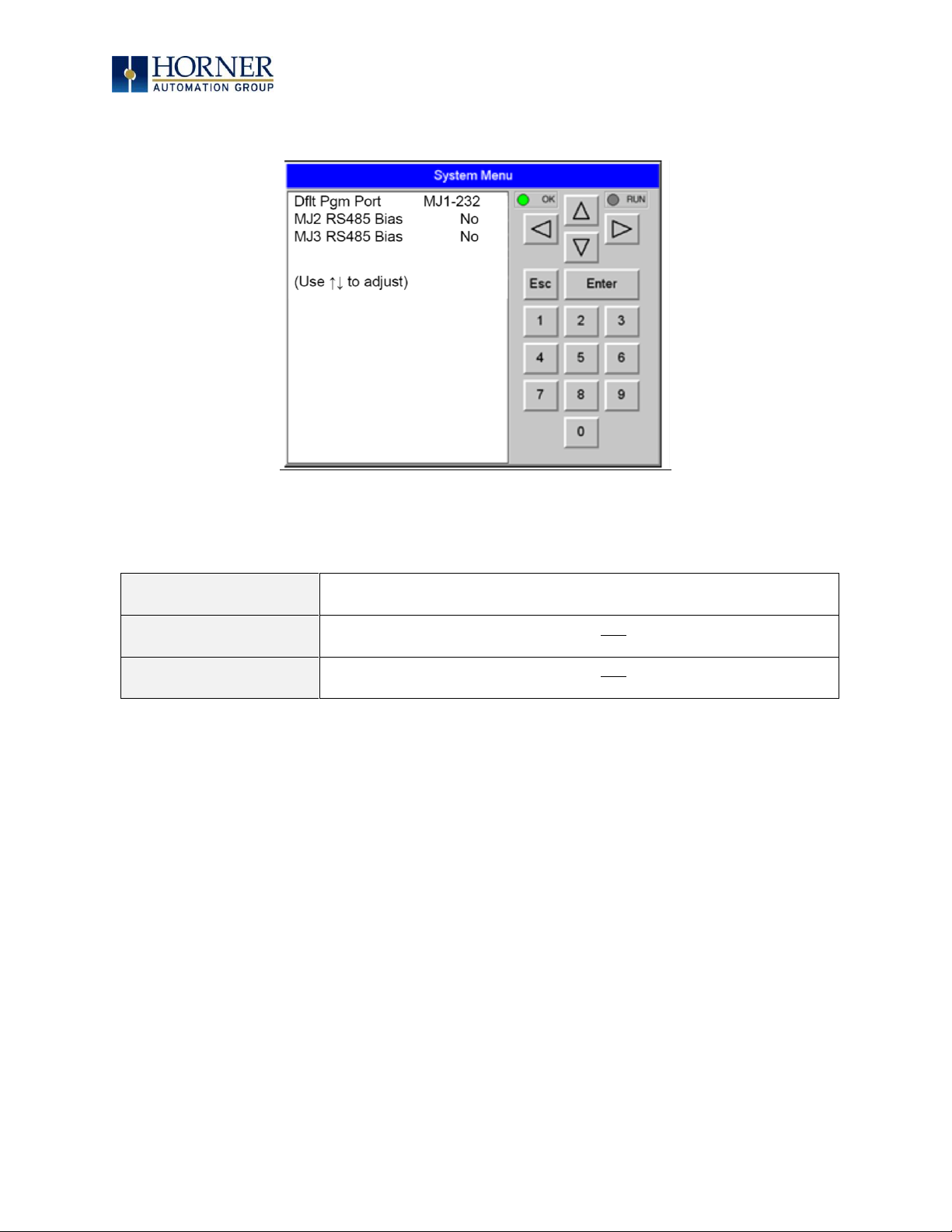
MAN0974-09-EN_XL7_UserManual
March 4th, 2019 Page 54 | 185
Set Serial Ports
The Set Serial Ports Sub-Menu displays three System Settings, all of which may be edited, and
one optional item. For the Dflt Pgm Port System setting, only MJ1-232 can be selected, unless
a Modem (XMC) COM module is installed.
Dflt Pgm Port
MJ1-232= MJ1 RS232 port is the default programming port
Modem= Modem COM module is the default programming port
MJ2 RS485 Bias
No = MJ2 RS485 bias resistors are not switched in
Yes = MJ2 RS485 bias resistors are switched in
MJ3 RS485 Bias
No = MJ3 R5485 bias resistors are not switched in
Yes = MJ3 R5485 bias resistors are switched in
Page 55

MAN0974-09-EN_XL7_UserManual
March 4th, 2019 Page 55 | 185
Set Time/Date
The following instructions are to set and display the real-time clock in the controller. More
details can be found in the Help File in Cscape.
Table 9.1 Clock and Time Setting Terms
Coordinated Universal Time
(UTC)
Abbreviated to UTC, Coordinated Universal Time is the
primary time standard by which the world regulates
clocks and time.
Time Offset
In order to obtain the local time (anywhere in the
world), user needs to subtract / add a certain number
of hours from UTC depending on how many time zones
user is away from Greenwich.
Network Time Protocol (NTP)
A Networking Time Protocol (NTP) for clock
synchronization between computer systems over
packet-switched, variable latency data networks.
Daylight Saving Time
Time as adjusted to achieve longer evening daylight,
especially in summer, by setting the clocks an hour
ahead of the standard time.
Apply Daylight Saving (DST)
Daylight Saving Time (DST) is the practice of setting
the clocks forward one hour from standard time during
the summer months, and back again in the fall, in order
to make better use of natural daylight. Selecting this
option increases the Time offset by 1 hour.
NOTE: Not all controllers contain real-time clocks.
NOTE: Controller Time Zone (UTC time): From Cscape 9.70 SP2 and FW 14.22 onwards, UTC
time is supported.
Table 9.2 – System Registers for UTC (Coordinated Universal Time)
%SR210 (R/W)
Time Zone: set in hours + / - UTC.
%SR211 (R/W)
Daylight Saving: YES = 1
Daylight Saving: NO = 0
(If daylight saving is enabled, one hour will be added
to the local time).
%SR212 (R)
UTC – Seconds
%SR213 (R)
UTC – Minutes
%SR214 (R)
UTC – Hours
%SR215 (R)
UTC – Date
%SR216 (R)
UTC – Month
%SR217 (R)
UTC – Year
Page 56

MAN0974-09-EN_XL7_UserManual
March 4th, 2019 Page 56 | 185
To Set Time Zone: The Time Zone setting is an hourly offset from UTC time. If using the Time
Zone setting, set it first, then set the local time. UTC time will be automatically set based on
the time zone and local time settings.
If using NTP: NTP utilizes UTC time, therefore when using NTP, the appropriate hourly offset
from UTC time must entered into the time zone setting.
Daylight Saving Time: If currently observing Daylight Saving Time, set to Yes. If not currently
observing Daylight Saving Time, set to No. The OCS controller does not automatically switch
to daylight saving time; however, program logic can be written to accomplish an automatic
switchover using system register %SR211. In program logic, move a “1” (INT) into %SR211 to
enable Daylight Saving Time. Move a “0” (INT) into %SR211 to disable Daylight Saving Time.
Trigger the move to %SR211 based on a compare function to the RTC date according to
daylight saving practices in your desired region.
To Set Local Time: The Set Time/Date sub-menu displays three system settings. Time and Date
may be edited, and Day is automatically calculated from the Date setting.
NOTE: Time and Date are split into three fields each, all of which may be edited. Touch the field
or use or buttons to select a field, then use the or buttons to edit the field.
Time
16:09:49 = Current time (hours:minutes:seconds in 24-hour
format)
Date
10-Jun-2013 = Current date (day-month-year)
Day
Monday = Current day of week calculated from the Date setting
Page 57

MAN0974-09-EN_XL7_UserManual
March 4th, 2019 Page 57 | 185
Set Beeper
The Set Beeper Sub-Menu displays one System Setting, which may be edited.
Beeper Enable
Yes
(default)
= Enables beeper
No = Disables beeper
(does NOT affect ladder access)
Page 58

MAN0974-09-EN_XL7_UserManual
March 4th, 2019 Page 58 | 185
Set Screen
The Set Screen Sub-Menu displays four System Settings, all of which may be edited.
Saver enable
Yes = Enable screen saver
No
(default)
= Disable screen saver
Timeout (min)
5 - 1200 = Amount of time in minutes to expire with NO touch
activity before activating screen saver (black screen)
Popup Status
Off
(default)
= Disable popup status
Warning = Display popup status only if controller status changes
to NOT Ok or NOT Run mode.
On = Display popup status on any controller status change.
Update Time (mS)
2 - 50 = Maximum amount of time to allow for graphics update
per scan
Page 59

MAN0974-09-EN_XL7_UserManual
March 4th, 2019 Page 59 | 185
Removable Media
The Removable Media Sub-Menu displays the Removable Media Manager. Having selected
Removable Media from the Main Menu, one of four Sub-Menu screens will appear:
If a directory name is highlighted, pressing Enter will switch to that directory showing its files
and sub-directories. In a sub-directory, highlighting “..” (dot dot) and pressing Enter will move
up one directory.
Media Directory
No Card
Media Directory
Dir Empty
Media Directory
Initializing
= No microSD card has been installed in the memory slot
= microSD card is installed, but it is still initializing
= microSD card is installed and initialized, but contains
no files
Shows size of highlighted file or shows <DIR> if directory is highlighted
Shows the date file or directory was created or last modified
Shows the time file or directory was created or last modified
= microSD card is installed and initialized, and it contains
Page 60
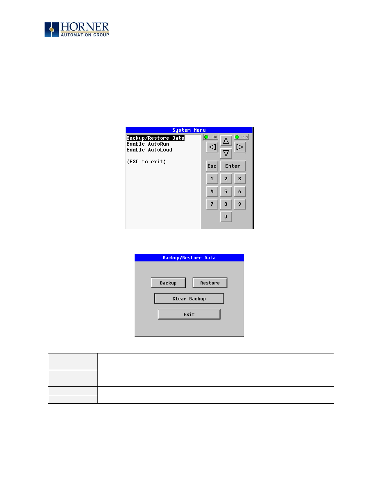
MAN0974-09-EN_XL7_UserManual
March 4th, 2019 Page 60 | 185
Fail – Safe System
The Fail-Safe System is a set of features that allow an application to continue running in the
event of certain types of "soft" failures. These "soft" failures include:
• Battery power loss
• Battery-Backed Register RAM or Application Flash corruption due to, for example, an
excessive EMI event.
Selecting “Fail-Safe System” menu will open the following menu screen:
Selecting Backup/Restore Data displays the following screen in:
Backup
= Copies Battery Backed RAM contents on to the onboard flash memory of
the OCS.
Restore
= Copies the backed up data from onboard flash memory to the battery
backed RAM.
Clear Backup
= The backup data will be erased from the onboard flash memory.
Exit
= Goes back to previous menu
Page 61

MAN0974-09-EN_XL7_UserManual
March 4th, 2019 Page 61 | 185
Enable AutoRun
“Enable AutoRun” displays the following options which can be selected:
Enable AutoRun
No = OCS will be in IDLE mode after AutoLoad or Automatic Restore.
Yes = OCS will automatically be placed into RUN mode after
AutoLoad or Automatic Restore.
Page 62

MAN0974-09-EN_XL7_UserManual
March 4th, 2019 Page 62 | 185
Enable AutoLoad
“Enable AutoLoad” displays the following options which can be selected:
Enable AutoLoad
No = Does not load AUTOLOAD.PGM automatically when application
program is absent or corrupted.
Yes = Loads AUTOLOAD.PGM file automatically from RM when
application program is absent or corrupted.
Page 63
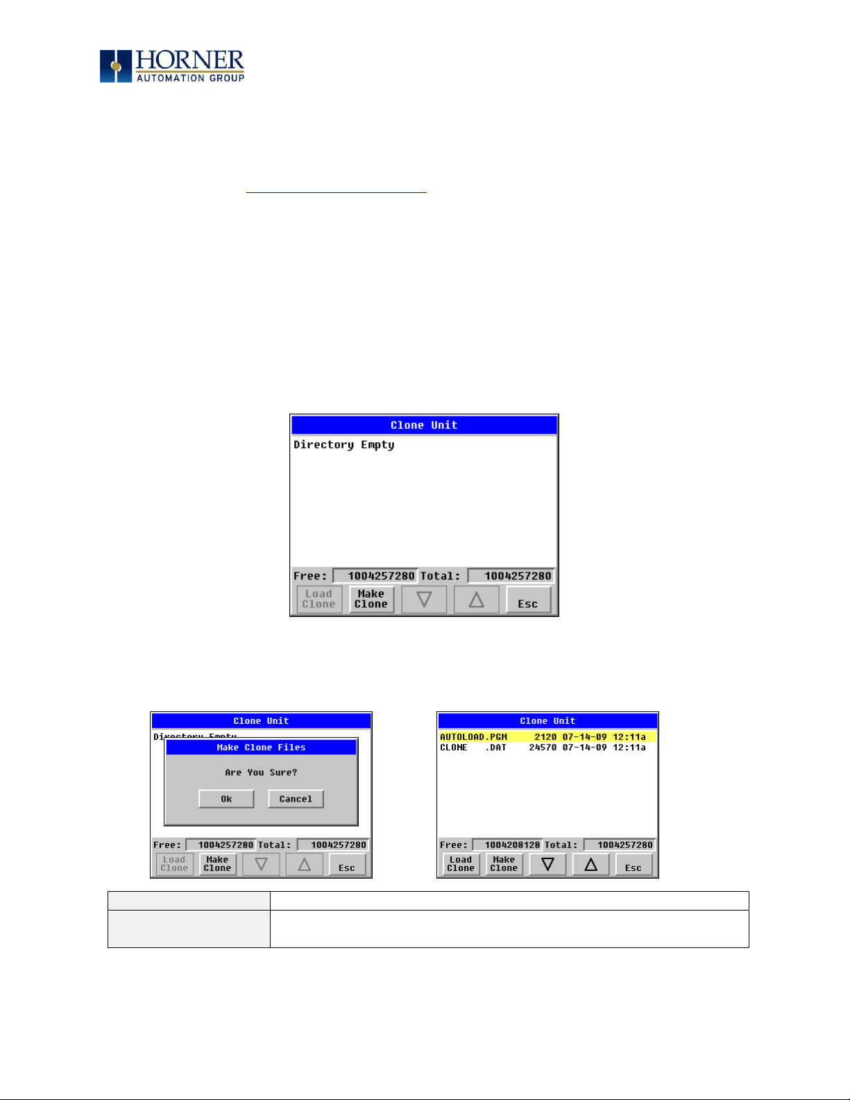
MAN0974-09-EN_XL7_UserManual
March 4th, 2019 Page 63 | 185
Clone Unit
‘Clone Unit’ feature allows the user to “clone” the OCS of the exact same model. This feature
“clones” application program and unit settings stored in Battery backed RAM of an OCS into
the RM. Refer to the Removable Media Chapter for details on using RM). It can then be used to
clone a different OCS (exact same model).
This feature can be used when:
- Replacing an OCS by another unit of the same model.
- Duplicating or “clone” units without a PC.
Make Clone
Selecting “Clone Unit” menu will open the following menu screen:
NOTE: Free/Total – displays number of free and total bytes in Removable Media.
Selecting Make Clone brings up the confirmation screen. Upon confirmation, the OCS will
create two new files in the root directory of the Removable Media Drive as shown below:
AUTOLOAD.PGM
Application file
CLONE.DAT
File having all unit settings and register values from Battery
Backed RAM
Page 64

MAN0974-09-EN_XL7_UserManual
March 4th, 2019 Page 64 | 185
Load Clone
Selecting “Clone Unit” menu will open the following menu screen. Select “Load Clone”.
NOTE: For security enabled files, Load clone asks for password validation before loading the
application.
Page 65

MAN0974-09-EN_XL7_UserManual
March 4th, 2019 Page 65 | 185
WebMI License Details
License details page displays the information about the WebMI license. Refer to MAN1036 for
the WebMI Manual for more details. The information can also be viewed from Cscape using the
following %SR registers:
%SR209.3
WebMI server status
%SR209.4
WebMI user logged in status
%SR209.8 to SR209.16
Number of Users
%SR218
Number of Webpages
%SR219
Number of Data Points
%SR220-SR222
Expiry Date of WebMI License
Page 66

MAN0974-09-EN_XL7_UserManual
March 4th, 2019 Page 66 | 185
9.4 Touch screen calibration
The touch screen is calibrated at the factory and rarely needs modification. However, if actual
touch locations do not appear to correspond with responding objects on the display, field
adjustment is available. Ensure SYS_fn Enable is set to YES in the System Menu. To access the
field adjustable touch screen calibration dialog, press and hold both the SYS and F1 key for
longer than 2 seconds and a dialog similar to Figure 9.3 should appear. Thereafter, use a
plastic tip stylus and follow the dialog instructions.
For best results in screen calibration, use a stylus with a plastic tip. When the crosshair
appears, touch the center of the crosshair as exactly as possible and release. A small “+”
should appear and will move closer to the center of the crosshair. Once it has done so and
disappeared again, repeat the process until “+” appears in the center of the crosshair. Then
move on to the next step.
Figure 9.3—Screen Calibration
Page 67

MAN0974-09-EN_XL7_UserManual
March 4th, 2019 Page 67 | 185
CHAPTER 10: REMOVABLE MEDIA
10.1 Overview
All XL7 OCS models provide a Removable Media slot, labeled Memory Card, which supports
standard microSD flash memory cards. The microSD cards can be used to save and load
applications, to capture graphics screens and to log data for later retrieval.
Figure 10.1 – Removable microSD Memory Card Slot
10.2 microSD Cards
When the microSD card format was introduced, it was originally called TransFlash. Cards labeled
either microSD or TransFlash, with up to 32GB of flash memory, are compatible with the XL7
OCS Memory slot (larger sizes were not tested at time of publication).
The Memory slot is equipped with a “push-in, push-out” connector and a microSD card can be
safely inserted into the Memory slot whether the XL7 OCS power is On or Off.
To install a microSD card:
Align its 8-pin gold edge connector down, facing the front of the XL7
OCS unit; then carefully push it all the way into the Memory slot. Ensure that it clicks into place.
To remove the microSD card
: Push in on the top of the card gently to release the spring. The
card pops out for removal.
10.3 microSD File System
The microSD memory card slot uses the PC-compatible FAT32 File System. This means that a
PC, with a microSD-compatible card reader, can read files that have been written by the XL7
OCS and can write files that can be read by the XL7 OCS.
However, the XL7 OCS does not support long filenames, but instead implements the 8.3
filename format. This means that all file and directory names must consist of up to eight (8)
characters, followed by an optional dot, and an optional extension with up to three (3)
characters.
Directories and sub-directories can be nested up to 16 levels deep as long as each pathname
string does not exceed 147 characters.
Page 68

MAN0974-09-EN_XL7_UserManual
March 4th, 2019 Page 68 | 185
10.4 Using the Removable Media Manager
The Removable Media Manager is an interactive XL7 OCS screen that performs the following
functions:
a. Display number of total and free K bytes
b. Browse file and directory lists
c. Delete files and directories
d. Format a microSD card
e. Load and save application programs
f. View screen capture bitmaps
The Removable Media Manager can be accessed via the System Menu or by using Cscape to
place a Removable Media Manager object on an application graphics screen.
Figure 10.2 – Removable Media Submenu
10.5 Using Removable Media to Log Data
Using Read and Write Removable Media function blocks, an application ladder program can
read and write XL7 OCS register data in the form of comma-delimited files, with a .CSV
extension. These files are compatible with standard database and spreadsheet PC programs.
In addition, an application ladder program can use Rename and Delete Removable Media
function blocks to rename and delete files.
Page 69

MAN0974-09-EN_XL7_UserManual
March 4th, 2019 Page 69 | 185
10.6 Using Removable Media to Load and Save Applications
A special file type, with a .PGM extension, is used to store XL7 OCS application programs on
microSD.
To load an application from microSD to the XL7 OCS, use the Removable Media Manager
(open the Removable Media Manager in the System Menu) to find and highlight the desired
.PGM file, and then press the Enter key.
To save an application from the XL7 to microSD, open the Removable Media Manager in the
System Menu and press the Save Pgm function key. The application will be saved in a file
called DEFAULT.PGM in the microSD root directory.
NOTE: Saving an application to microSD can only be done from the Removable Media
System Menu and is not available on a Removable Media Manager object that was
placed on an application graphics screen by Cscape.
NOTE: Cscape can also save an application directly to a microSD card, which is plugged into
the PC’s microSD compatible card reader by selecting the Export to Removable Media item on
the Cscape File menu.
10.7 Using Removable Media to View and Capture Screens
The XL7 OCS File System uses bitmap files with the .BMP extension or JPEG files with the
.JPG extension to store XL7 OCS graphic screen captures.
To view a captured XL7 OCS screen, use the Removable Media Manager to find and highlight
the desired .BMP or .JPG file, and then press Enter.
Before capturing an XL7 OCS screen, Cscape must first be used to assign a Screen Capture
Control Register and Filename in the application. To do this, first open the Graphics Editor by
selecting the View / Edit Screens item on the Cscape Screens menu. Next, select the Screen
Capture item of the Graphics Editor Config menu and then enter a Control Register and
Filename.
To capture an XL7 OCS screen, turning On the assigned Screen Capture Control Register will
capture the current XL7 OCS graphics screen and write it to the microSD card using the
assigned Screen Capture Filename. To view a captured XL7 OCS screen, use the Removable
Media Manager to find and highlight the desired .BMP or .JPG file, and then press Enter.
Page 70

MAN0974-09-EN_XL7_UserManual
March 4th, 2019 Page 70 | 185
10.8 Configuration of a Removable Media
The configuration of the Removable Media Object that loads the Removable Media Viewer
defines what buttons are enabled and available to the user.
The (Enter) button performs certain operations based on the selected file’s type:
.. - change display to parent directory
<DIR> - change display to child directory
pgm - load application (if compatible model and version)
Alternately, by checking the ‘Write Selected Filename’ option, the RM Manager object will load
the currently displayed path and filename into a block of registers for use with other
Removable Media functions. The register block is assigned in the ‘File Select’ config found in
the Config menu of the graphic/screen editor.
Once view operations are complete, simply touch the Esc button to remove the pop-up
removable media viewer.
10.9 Removable Media (RM) Function Blocks in Cscape
NOTE: For detailed information regarding RM function blocks and parameters, refer to the
help file
in Cscape Software. Refer ‘USB flash Media support for RM Functions’ for USB flash drive
access details.
The following RM functional blocks are available in Cscape Software. These function blocks will
reference
- microSD when filename is prefixed with ‘A:’ or nothing OR
- USB A flash Drive when filename is prefixed with ‘B:’.
Read RM csv
Allows reading of a comma-separated value file from the microSD
interface into the controller register space.
Write RM csv
Allows writing of a comma-separated value file to the microSD
interface from the controller register space.
Rename RM csv
Allows renaming a file on the RM card. The data in the file is not
changed.
Delete RM csv
Allows deleting a file on the RM card
Copy RM csv
Allows copying a file on the RM card. The data in the file is not
changed.
Table 10.1 – RM Functional Blocks
Page 71

MAN0974-09-EN_XL7_UserManual
March 4th, 2019 Page 71 | 185
10.10 Removable Media (RM) Features—Program Features
a. Datalog Configuration—This feature allows the controller to periodically log register values
to Removable Media. The register data is stored in .csv (comma separated value) format,
which is compatible with 3rd party PC applications, such as Microsoft Excel.
b. Report Editor—This feature allows the OCS to be configured to generate text printouts
which incorporate data from the registers embedded in the text. The reports can be printed
using a serial interface printer through any of the serial ports of the OCS or can be saved on
the removable media of the device.
c. Recipes Editor—Recipes allow the user to send or update multiple registers simultaneously.
10.11 Removable Media (RM) Features—Graphic/Screen Editor
a. Trends—The historic support feature in the trend object utilizes Removable Media.
b. Removable Media—This is a graphic object used to access files and functions pertaining to
Removable Media.
c. Recipes—This is a graphic object that is used in conjunction with the recipe editor which is
mentioned above.
10.12 Removable Media (RM) Features—Additional Configuration
a. Alarms—Alarm data can be logged to a .csv file stored on Removable Media.
b. Screen Capture—The screen capture function allows a bitmap or jpeg image of the displayed
OCS screen to be written to the Removable Media card.
c. Filename Counters— The filename counters can be accessed wherever Removable Media
functions require a path name. A typical application is the auto-incrementing of a file name
when doing screen captures.
d. File Select— File Select is used to specify the register block that is used with the Removable
Media Manager object ‘Write Selected Filename’ option.
Page 72

MAN0974-09-EN_XL7_UserManual
March 4th, 2019 Page 72 | 185
10.13 Filenames used with the Removable Media (RM) Function Blocks
The RM function blocks support the flash with a DOS/Windows standard FAT-16 file system. All
names must be limited to the “8.3” format where the filename contains eight characters a
period then a three-character extension. The entire filename including any path must be less
than or equal to 147 characters.
When creating filenames and directories it is sometimes desirable to include parts of the current
date or time. There are six special symbols that can be entered into a filename that are replaced
by the OCS with current time and date information.
Table 10.2 – Filename Special Symbols
Symbol
Description
Example
$Y
Substitutes the current 2 digit year
2015 = 15
$M
Substitutes the current month with a 2 digit code
March = 03
$D
Substitutes the current day
22nd = 22
$h
Substitutes the current hour in 24 hour format
4 pm = 16
$m
Substitutes the current minute
45 = 45
$s
Substitutes the current second
34 = 34
NOTE: All the symbols start with the dollar sign ($) character. Date symbols are in upper case,
time symbols are in lower case. The following are examples of the substituted time/date
filenames:
Current date and time
= March 1, 2013 3:45:34 PM
Filename: Data$M$D.csv
= Data0301.csv
Filename: Year$Y\Month$M\aa$D_$h.csv
= Year04\Month03\aa01_15.csv
Filename:
Month_$M\Day_$D\$h_$m_$s.csv
= Month_03\Day_01\15_45_34.csv
Table 10.3 – Filename Examples
Page 73

MAN0974-09-EN_XL7_UserManual
March 4th, 2019 Page 73 | 185
10.14 System Registers used with RM
Table 10.4 – System Registers used with RM
%SR174 Removable
Media Protect
Write a 1 to %SR174 to prohibit read/write access to the
removable media card. Write a zero (0) to allow access.
%SR175 Status
This shows the current status of the RM interface
%SR176 Free Space
This 32-bit register shows the free space on the RM card in bytes
%SR178 Card
Capacity
This 32-bit register shows the total card capacity in kilobytes
Possible status values are shown in the table:
For additional status information, consult the Cscape Help file.
Table 10.5 – RM Status Values
0
RM interface OK
1
Card present but unknown format
2
No card in slot
3
Card present, but not supported
4
Card swapped before operation was complete
5
Unknown error
Page 74

MAN0974-09-EN_XL7_UserManual
March 4th, 2019 Page 74 | 185
CHAPTER 11: GENERAL I/O
NOTE: The datasheet is the first document to refer to for model-specific information related to
XL7 OCS models such as pin-outs, jumper settings, and other key installation information. Visit
the Horner websites to obtain datasheets, user documentation, and updates.
11.1 Overview
The XL7 OCS is a compact unit that contains high density, very versatile I/O. Using the I/O
properly requires wiring to the proper terminals, configuring jumpers inside the XL7 OCS unit
and configuring Cscape properly. This section will offer some tips and suggestions to configure
the I/O properly. For the register mapping of the I/O, refer to the Index at the end of this manual
for the pages referencing register mapping.
11.2 Removing the XL7 OCS I/O Cover
Some I/O configurations require jumper settings to be changed in the XL7 OCS unit. Examples
of these settings are setting positive or negative logic on digital inputs or setting current or
voltage on analog inputs.
Each XL7 OCS I/O jumper is set to a factory default. Refer to the XL7 datasheet to find the
default setting to determine if a jumper change is necessary for a particular application.
To remove the I/O cover of the XL7 OCS, remove the four (4) Phillips screws from the I/O
back. It may help to place the XL7 OCS unit face down on a clean work surface. Once the four
screws are removed the I/O cover can be lifted straight off.
Figure 11.1 – Removing the I/O Cover
WARNING: Power, including I/O power, must be removed from the unit prior to removing
the back cover. Failure to do so could result in electrocution and/or damage to equipment.
Wiring Details
Solid/Stranded Wire: 12-24 awg (2.5 – 0.2mm2)
Strip Length: 0.28” (7mm)
Torque Rating: 4.5 – 7 in-lbs (050 – 0.78 N-m)
Page 75

MAN0974-09-EN_XL7_UserManual
March 4th, 2019 Page 75 | 185
Figure 11.2 – XL7 I/O Cover Removed (sample I/O board)
Once the back is removed the jumper selection can be changed. The jumper settings are
documented on each data sheet using a diagram such as Figure 11.3 below and a description of
the jumper settings.
Figure 11.3 – Example Jumper Diagram
To re-install the cover, place the I/O cover back on the unit.
Place the screw back into the hole and turn the screw slowly counter clockwise until it clicks
into the threads. This prevents the screw from being cross-threaded. Now turn the screw clockwise until the cover is firmly secured. Repeat this process for all four (4) screws. Ensure not to
exceed the recommended max torque of 7-10 in-lbs [0.8 – 1.13 Nm].
J1 J2
J3
JP3
JP1
001XLE005-R1
J4
Page 76

MAN0974-09-EN_XL7_UserManual
March 4th, 2019 Page 76 | 185
11.3 Model and I/O Overview
Table 11.1 – I/O and Model Overview
XL7 Models
DC In
DC
Out
Relays
HS In
HS
Out
mA/V
In
mA/V
RTD/TC
mA/V
Out
HE-XW1E0 /
HEXT391C100
HE-XW1E2 /
HEXT391C112
12 6 4 4
HE-XW1E3 /
HEXT391C113
12
12 4 2 2
HE-XW1E4 /
HEXT391C114
24
16 4 2 2
HE-XW1E5 /
HEXT391C115
12
12 4 2 2 2
HE-EXV1E6/
HEXT505C116
12
12 4 2 6 4
Page 77

MAN0974-09-EN_XL7_UserManual
March 4th, 2019 Page 77 | 185
11.4 Solid-State Digital Outputs
Solid-state digital outputs are generally used to activate lamps, low voltage solenoids, relays, and
other low voltage and low current devices.
NOTE: The digital outputs used on the XL7 OCS are “sourcing” outputs. This means the output
applies a positive voltage to the output pin when turned ON. When turned off, the output applies
approximately zero volts with respect to the I/O ground.
Figure 11.4 – Typical Output Wiring
The digital outputs used in the XL7 OCS have electronic short circuit protection and current
limiting. While these electronic protections work in most applications, some application may
require external fusing on these outputs.
The digital outputs in the XL7 OCS are typically controlled via %Q bits in the register mapping.
Some of the outputs are designed for high-speed applications and can be used for PWM or
frequency output applications. Please see the data sheet and the chapter on High Speed I/O for
additional information.
When the controller is stopped the operation of each output is configurable. The outputs can hold
the state they were in before the controller stopped or they can go to a predetermined state. By
default, digital outputs turn off. For more information on stop state see the Index to find pages
referencing Cscape settings.
The digital outputs feature an output fault bit. %I32 will turn on if any of the outputs experience a
short circuit, over-current or the output driver overheats.
Q14
Q15
V+
0V
LOAD
LOAD
10 - 30VDC
Q16
LOAD
J2
J4
Page 78

MAN0974-09-EN_XL7_UserManual
March 4th, 2019 Page 78 | 185
11.5 Relay Outputs
Relay outputs are designed to switch loads that typically have high voltage or current
requirements or require the isolation that relays provide.
NOTE: The design of the XL7 OCS does not require external coil power for the relays to function.
The relays will activate anytime the XL7 OCS is powered.
There are several factors that should be considered when using relays:
Relay Life – Relays are mechanical devices that have a long but limited life. Typically, switching more
current limits the life of relays. Please check the data sheets at the end of this manual for expected
relay life.
Current / Temperature Derating – Products containing relays often have total current limits based on
the ambient temperature of the application. Please see the product data sheet for current /
temperature derating information for relays.
Fusing – External fusing is generally required to protect the relays, devices and wiring from shorts or
overloads.
001XLE015
0V ON J1
12-24VDC
R2
C2
R3
C3
R6
C6
R4
C4
R5
C5
R1
C1
H4
H2
H3
LOAD
230VAC
OR
25VDC
N
L
LOAD
230VAC
OR
25VDC
N
L
LOAD
230VAC
OR
25VDC
N
L
LOAD
230VAC
OR
25VDC
N
L
LOAD
230VAC
OR
25VDC
N
L
LOAD
230VAC
OR
25VDC
N
L
Warning: To protect the module and associated wiring from load faults, use external (5A) fuse(s) as
shown. Fuses of lower current or fusing for the entire system need to be in place to assure
the maximum current rating of the unit is not exceeded.
Warning: Connecting high voltage to any I/O pin can cause high voltage to appear at other I/O pins.
Figure 11.5 – Relay Fusing
Page 79

MAN0974-09-EN_XL7_UserManual
March 4th, 2019 Page 79 | 185
Protection for Inductive Loads
Inductive loads can cause reverse currents when they shut off that can shorten the life of relay
contacts. Some protective measures need to be determined by an engineer. If you have questions
on protection from inductive load, consult Horner Automation Technical Support. Details on
devices that may protect outputs can be found in the Spark Quencher Datasheet, MAN0962.
Output State on Controller Stop
When the controller is stopped the operation of each output is configurable. The outputs can
hold the state they were in before the controller stopped or they can go to a predetermined
state. By default, relay outputs turn off. For more information on stop state see the Index for
Cscape settings pages.
Page 80

MAN0974-09-EN_XL7_UserManual
March 4th, 2019 Page 80 | 185
11.6 Digital Inputs
NOTE: Refer to the datasheet for XL7 OCS model being used for details on jumper settings.
NOTE: The digital inputs on the XL7 OCS are designed for low voltage DC inputs. The inputs are
designed to support both positive and negative input modes. The mode is set by a jumper setting
and a configuration parameter in Cscape. All the inputs on the unit must be configured to the
same mode.
Figure 11.6 – Positive and Negative Inputs
In positive logic mode a positive voltage applied to the input will turn the input. The internal
design of this mode is basically a resistor from the input to I/O ground. This mode is sometimes
called “sourcing”.
In negative logic mode, connecting the input to the I/O ground or zero volts will turn the input
on. The internal design of this mode is basically a resistor from the input to the positive I/O
voltage (usually 12V or 24V). This mode is sometimes called “sinking”.
Some of the digital inputs may support high-speed input functional such as counting or
frequency measurement.
I1
0V
001XLE036
12-24VDC
I1
0V
Positive Logic In Negative Logic In
Positive Logic vs. Negative Logic Wiring
The XL SERIES OCS can be wired for Positive Logic inputs or
Negative Logic inputs.
Page 81

MAN0974-09-EN_XL7_UserManual
March 4th, 2019 Page 81 | 185
11.7 Analog Inputs
NOTE: See the data sheet for the XL7 OCS model being used for jumper settings and see the
appropriate page in this manual (see Index) for details on how to use Cscape to configure the digital
filtering.
The analog inputs on the XL7 OCS allow voltage or current measurement from a variety of
devices. The voltage or current mode is set though jumpers on the unit and settings in Cscape.
Each channel can be separately configured for voltage or current mode.
The analog inputs have a digital filter that can be used to filter electrical noise that may be
unavoidable in some installations. The downside to digital filtering is the inputs will respond
more slowly to sudden changes in the actual input.
11.7.1 Thermistor Option for Special Orders
NOTE: The standard unit does NOT support thermistor.
Thermistor support is a factory option for Models 2, 3, and 4 only. Model 2 can support a twochannel and four-channel thermistor. Models 3 & 4 support the two-channel thermistor only.
Please refer to the Thermistor Supplement, SUP0797, for thermistor specifications and
implementation details.
11.7.2 Common Cause of Analog Input Tranzorb Failure, Models 2, 3, 4, & 5
If a 4-20mA circuit is initially wired with loop power but without a load, the analog input could
see 24VDC. This is higher than the rating of the tranzorb.
This can be solved by not connecting loop power prior to load connection or by installing a lowcost PTC in series between the load and the analog input.
Figure 11.7 – Analog Input Tranzorb - Troubleshooting
Page 82

MAN0974-09-EN_XL7_UserManual
March 4th, 2019 Page 82 | 185
11.8 Universal Analog Inputs
NOTE: See the data sheet for the XL7 OCS model being used for jumper settings and see the
appropriate pages in this manual (see Index) for details on how to use Cscape to configure the
digital filtering.
The universal analog inputs provide a high resolution, very flexible interface for a variety of
analog inputs. These inputs include voltage, current, thermocouple, RTD, and millivolt. Each
channel can be configured separately using jumpers and configuration settings in Cscape.
Like the standard analog inputs, these inputs have a digital filter that can be used to filter
electrical noise that may be unavoidable in some installations. The downside to digital filtering
is the inputs will respond more slowly to sudden changes in the actual input.
The Universal Analog Inputs on the Model 6 I/O board are unique from other Horner XL-series
input/output cards in that they are configurable through the module configuration instead of
having to change jumper settings in order to setup the input type.
To configure the Universal Analog input type:
1) Select Analog In to access the Analog Input Configuration menu.
2) Select any of the Analog input types from the dropdowns by clicking the down arrow
beneath each corresponding Channel, as seen below:
Figure 11.8 – Analog Input Configuration Screen
Page 83

MAN0974-09-EN_XL7_UserManual
March 4th, 2019 Page 83 | 185
3) Ensure the proper wiring is used for each of the 3 pins A , B, and C on the Universal Analog
Inputs as seen in the reference image below:
Figure 11.9 – Loop Power Requirements
11.9 Analog Outputs
NOTE: Refer to the datasheet for XL7 OCS model being used for details on jumper settings.
The analog outputs on XL7 OCS devices provide high-resolution voltage or current outputs. The
voltage or current selection is controlled with jumpers and configuration settings in Cscape.
NOTE: Each channel can be separately configured for voltage or current mode.
When the controller is stopped the operation of each output is configurable. The outputs can
hold the state they were in before the controller stopped or they can go to a predetermined
value. By default, analog outputs are set to a value of zero. For more information on Stop State,
refer to the appropriate pages (see Index) for the configuration chapter for Cscape settings.
Page 84

MAN0974-09-EN_XL7_UserManual
March 4th, 2019 Page 84 | 185
CHAPTER 12: HIGH SPEED I/O (HSC / PWM)
12.1 Overview
In addition to the compliment of simple analog and digital I/O, several of the XL7 OCS I/O
modules support High Speed Counting (HSC) I/O functions and may also support Pulse Width
Modulation (PWM) Output functions (non-relay modules). The HSC functions include internal
timing, frequency, totalizing, pulse width/period, and quadrature measurement. The PWM
functions include traditional PWM (with variable rate and duty cycle) and a stepper (limited
functionality) with variable acceleration and deceleration rates. To determine function
availability, refer to the associated model’s Specification/Installation sheet (Digital DC Input /
Output sections).
The OCS contains a Field-Programmable Gate Array (FPGA), which is an integrated
configurable circuit that allows the XL7 to be programmed to have either two high-speed
counters or four high-speed counters. The XL7 ships with two high-speed counters, but a
customer can contact Horner Technical Support to receive a file that will configure the unit to
have four. These modes are not supported simultaneously. Two counter mode supports
Quadrature mode and two stepper outputs, while four counter mode does not support
Quadrature mode and supports only one stepper output.
This chapter describes the operation of these high level I/O functions. For configuration
details of these functions, see Cscape Configuration.
Page 85

MAN0974-09-EN_XL7_UserManual
March 4th, 2019 Page 85 | 185
12.2 Glossary
Table 12.1 – Glossary of High Speed I/O Terms
Accumulator
Register used to accumulate or store up a sum or count of many items or
events.
Clear
A special function to zero out the value in a specific register. (Not used with
Frequency or Period Measurement.)
Disable
A special function to prevent the counter from running.
Encoder
A sensor or transducer for converting rotary motion or position to a series of
electronic pulses
FPGA
An integrated, configurable circuit that allows the controller to be
programmed to have either two high-speed counters or four high-speed
counters.
Frequency
Input
The number of times an electromagnetic signal repeats an identical cycle in a
unit of time, usually one second.
Latch
(strobe)
A special function that uses a digital logic circuit to store one or more bits. A
latch has a data input, a clock input and an output. When the clock input is
active, data on the input is "latched" or stored and transferred to the output
register either immediately or when the clock input goes inactive. The output
retains its value until the clock goes active again.
Marker
Input into the OCS that indicates a particular position. Typically, an encoder
has a marker output that represents a specific point in the rotation.
Polarity
A Polarity pull-down box is associated with each function and indicates the
manner in which the trigger happens (e.g., High level, Low Level, Falling
Edge, Rising Edge).
Preload
(load)
A special function used to trigger loading of a value into a register upon an
event. (Not used with Frequency or Period Measurement.)
Quadrature
A high-speed device that expresses the phase relationship between two
periodic quantities of the same period when the phase difference between
them is one fourth of a period. A coupler in which the two output signals are
90° out of phase.
Totalizer
A counter that sums the total number of cycles applied to its input.
Page 86

MAN0974-09-EN_XL7_UserManual
March 4th, 2019 Page 86 | 185
12.3 High Speed Counter (HSC) Functions
The XL7 supports two very high speed, configurable counters. There are four dedicated inputs
that can be configured to a number of different options. Each of the two counters can run in
one of five modes. Those modes are Totalizer, Frequency Counter, Pulse Width Measurement,
Period Measurement and Quadrature measurement. For some modes, more than one HSC
input may be consumed. The measurement values are provided to ladder in a %AI register.
Refer to the Registers chapter for more details.
12.3.1 Frequency
In frequency mode, the frequency of the input signal is written to the accumulator in terms of
Hertz (cycles/second). When using frequency mode, four update selections are provided
which specify the width of the sample window.
NOTE: Selecting a shorter sample window provides a quicker measurement (faster response)
but lowers the frequency accuracy (resolution) and increases the minimum frequency
measurement limit. In this mode the Disable and Latch special functions are allowed. Refer to
the HSC Glossary for a description of these functions.
Page 87

MAN0974-09-EN_XL7_UserManual
March 4th, 2019 Page 87 | 185
12.3.2 Totalize
In totalize mode, the accumulator is simply incremented or decremented each time the input
transitions in a specific direction.
The totalizer supports the following modes:
Internal
This mode ties the input to the counter to an internal 10MHz or
1MHz clock. The special functions can be used to accurately time
events.
Count Up
This increments the accumulator when the input is enabled.
NOTE: Two inputs can be assigned. Either input can cause the
counter to increment. The second input can also be disabled.
Count Down
This decrements the accumulator when the input is enabled.
NOTE: Two inputs can be assigned. Either input can cause the
counter to decrement. The second input can also be disabled.
Up/Down
(Input 1 Up/Input 2
Down)
In this mode, Input 1 (assigned to any of the four inputs)
increments the counter, while Input 2 (also assigned to any of the
4 inputs) decrements the counter.
Clk/Dir
(Input 1 Clk, Input 2
Dir)
This mode uses input 1 as a clock signal to increment or decrement
the counter and then uses input 2 to decide the direction. Input 2
disabled increments the counter, while input 2 enabled
decrements the counter.
Table 12.2 – Modes supported by Totalizer
NOTE: The totalize mode enables the Disable, Latch, Preload, and Clear special functions.
Refer to the HSC Glossary for a description of these functions.
NOTE: Counter triggers off the rising edge of the signal.
Page 88

MAN0974-09-EN_XL7_UserManual
March 4th, 2019 Page 88 | 185
Three different options are available to reset the current count. They are:
• Configured reset value
When configuring the Totalize function, a value may be specified under the
Counts per
Rev
column. When the totalizer accumulator reaches this value - 1, the accumulator will
reset to zero on the next count. Specifying zero for this value allows the totalizer to
count through the full 32-bit range before resetting.
• Ladder control
Setting registers %Q17-20 reset HSC1-4 (respectively) with no additional configuration.
When these registers are asserted, the associated totalizer accumulator is reset and
held at zero (level sensitive).
• Direct digital input control (HSC1 and HSC2 only)
HSC3 (%I11) and HSC4 (%I12) may be configured as hardware digital reset signals for
HSC1 and HSC2 (respectively). To enable these inputs as reset signals, specify the type
as
Totalize Reset
(NOTE: The corresponding Totalize HSC must be previously
configured before this option is available). The direct digital reset controls are edge
sensitive with the edge polarity configurable.
Maximum direct digital reset latency is 100μs.
The totalize function also supports an option which compares the current accumulator value
with a supplied Preset Value (PV), which is provided through a %AQ, and drives a physical
digital output based on the that comparison.
• This option (available for HSC1 and HSC2 only) drives Q1 or Q2 output point
(respectively) once the associated totalizer accumulator reaches (or exceeds) the PV
value. To enable this function, the corresponding PWM function output (Q1 or Q2) must
be configured for
HSCx Output
.
NOTE: Q1 and Q2 are PWM function outputs that may be configured independently as one of
the following: standard digital output, PWM, HSCx or stepper output.
Preset values may be modified during run-time. A preset value of zero disables (resets) the
totalizer compares function output causing the output to remain low.
Rising Edge Signal
Falling Edge Signal
Page 89

MAN0974-09-EN_XL7_UserManual
March 4th, 2019 Page 89 | 185
12.3.3 Pulse Width Measurement
In pulse width measurement mode, the high-speed input can measure the width of a pulse
stream in one of two modes and provides a continuous indication of the last sampled value. In
this mode the Disable and Latch special functions are allowed. Refer to the HSC Glossary for a
description of these functions.
Width High 1 μs Counts – In this sub-mode the accumulator value will contain the number of 1 μs
counts the pulse is high.
Width Low 1 μs Counts - In this sub-mode the accumulator value will contain the number of 1 μs
counts the pulse is low.
Figures 12.1-12.2 - Pulse Width Measurements, High & Low
Width High
Width Low
Page 90

MAN0974-09-EN_XL7_UserManual
March 4th, 2019 Page 90 | 185
12.3.4 Period Measurement
In period measurement mode, the high-speed input can measure the period of a pulse stream
in one of two modes and provides a continuous indication of the last sampled value. In this
mode, the Disable and Latch special functions are allowed. Refer to the HSC Glossary for a
description of these functions.
Period Rising Edges 1 μs Counts – In this sub-mode the period of the input signal is reported in
one (1) μs units. The period measurement will start on the rising edge of the input.
Period Falling Edges 1 μs Counts – In this sub-mode the period of the input signal is reported in
1 μs units. The period measurement will start on the falling edge of the input.
Figures 12.3-12.4 – Period Measurement, Rising Edges & Falling Edges
Period from Rising Edge
Period from Falling Edge
Page 91

MAN0974-09-EN_XL7_UserManual
March 4th, 2019 Page 91 | 185
12.3.5 Quadrature
Quadrature mode uses two HSC inputs, any of the four HSC inputs can be assigned for this
purpose.
Quadrature mode works much like the totalizer except the accumulator will automatically
increment or decrement based on the rotation phase of the two inputs. See the following
example for more details. Quadrature inputs are typically used for reporting the value of an
encoder.
Two modes are available for quadrature that select whether the accumulator counts up or down
when the phase of Input 1 leads Input 2. Check your encoder’s documentation to determine the
output form it uses or try both modes to determine if the encoder counts up when expected.
Figure 12.5 – Quadrature
Using the above waveforms and a HSC input configuration of “Quadrature” - “1 leads 2, count
up,” the accumulator will count up when 1 is rising and 2 is low, 1 is high and 2 is rising, 1 is
falling and 2 is high, and when 1 is low and 2 is falling. This results in 4 counts per revolution.
So in order to determine the number of cycles, the accumulator would have to be divided by 4.
Marker reset operation is configured in the special operations and can be assigned to any of
the 4 high speed inputs or can be assigned to be controlled by a “Q” bit in ladder.
NOTE: The quadrature mode enables the Disable, Latch, Preload, Clear and Marker special
functions. Refer to the HSC Glossary for a description of these functions.
90°
phase
shift
1 (leading)
2 (lagging)
Page 92

MAN0974-09-EN_XL7_UserManual
March 4th, 2019 Page 92 | 185
12.3.6 Register Match
All counter modes support a register match function. When the accumulator value matches the
Match 1 or Match 2 value setup in %AQ registers a high-speed output with either turn on, turn
off or toggle based on settings in Cscape.
12.3.7 HSC Functions
The high-speed input on the XL7 contains many optional tasks. All of which can be disabled, or
set to an internal pre-assigned register (Assigned %Q) or to one of the external high speed
inputs (External Input #1, 2, 3, or 4), or they can be set as an “overflow interrupt” or
“underflow interrupt” meaning that they will occur when either the Overflow or Underflow
input has been activated.
Disable: When the Disable function is active, it will “disable” the high-speed inputs and no
longer count pulses until it is re-enabled
Latch: When the Latch function is active, it takes the current value of the Accumulator and
moves it into the “Latch Value” register
Preload: When the pre-load function is active, it will take the value from the “Preload” register
and put it into the “Accumulator” for the corresponding Counter.
Clear: When the clear function is active, it will move a value of 0 into the “Accumulator” for
the corresponding counter.
Marker: When the marker function is enabled, it acts as a dynamic enable/disable for the
Disable, Latch, Preload, and Clear functions. If the marker is enabled and “Assigned %Q” is
selected, then both the “Disable” and the “Disable Marker” bits need to be set high in order to
disable the high-speed input. If the Marker is set for one of the inputs, then the input will need
to be “High” in order to use any of the Disable, Clear, Preload, or Latch functions.
Page 93

MAN0974-09-EN_XL7_UserManual
March 4th, 2019 Page 93 | 185
12.3.8 Status Bits
There are three status bits (%I registers for each high-speed counter).
Overflow Flag: This status bit turns high when the Accumulator “overflows”, it moves from
4,294,967,295 (-1 if Signed) to 0, this bit can be reset with the “Output Reset Bit”. See Table
11.4.
Underflow Flag: This status bit turns high when the Accumulator “underflows”, it moves from
0 to 4,294,967,295 (-1 if Signed), this bit can also be reset with the “Output Reset Bit”.
NOTE: For the Overflow and Underflow flag registers, if using some sort of counter that
counts both up and down, going over the threshold to go negative, triggers the underflow, and
then going back over the threshold back into positive numbers will trigger the positive
register to go active.
High Speed Out: This register will follow the high-speed output assigned to the counter, it is
important to note that this register is still populated within the scan time so the value in this
register may not be up to date depending on the timing of the output (it should be up to date
within one scan).
Page 94

MAN0974-09-EN_XL7_UserManual
March 4th, 2019 Page 94 | 185
12.4 HSC Functions Register Map
The register assignments for the high-speed I/O can be moved via a setting in Cscape. The
values shown are the DEFAULT values and may not match the same starting point as the values
shown below.
Table 12.4 – HSC Functions Register Map for 2 HSC Configuration
Register
Frequency
Pulse
Totalize
Quad
%AI401-402
Accumulator - Counter 1
%AI403-404
Latch Value – Counter 1
%AI405-406
Accumulator – Counter 2
%AI407-408
Latch Value – Counter 2
%AQ401-402 Preload – Counter 1
%AQ403-404
Match1 – Counter 1
%AQ405-406
Match2 – Counter 1
%AQ407-408 Preload – Counter 2
%AQ409-410
Match1 – Counter 2
%AQ411-412
Match2 – Counter 2
%AQ413-424
Reserved
%Q1601
Latch – Counter 1
%Q1602
Preload – Counter 1
%Q1603
Clear – Counter 1
%Q1604
Disable – Counter 1
%Q1605
Direction – C 1
%Q1606
Output Reset – Counter 1
%Q1607
Preload Disable – Counter 1
%Q1608
Latch Disable – Counter 1
%Q1609
Disable Marker – C1
%Q1610
Latch Marker – C1
%Q1611
Preload Marker – C1
%Q1612
Clear Marker – C1
%Q1613-1616
Reserved
%Q1617
Latch – Counter 2
%Q1618
Preload – Counter 2
%Q1619
Clear – Counter 2
%Q1620
Disable – Counter 2
%Q1621
Direction – C2
%Q1622
Output Reset – Counter 2
%Q1623
Preload Disable – Counter 2
%Q1624
Latch Disable – Counter 2
%Q1625
Disable Marker – C2
%Q1626
Latch Marker – C2
%Q1627
Preload Marker – C2
%Q1628
Clear Marker – C2
%I1601
Overflow Flag – Counter 1
%I1602
Underflow Flag – Counter 1
%I1603
High Speed Out 1
%I1604
Reserved
%I1605
Overflow Flag – Counter 2
%I1606
Underflow Flag – Counter 2
%I1607
High Speed Out 2
%I1608
Reserved
Page 95

MAN0974-09-EN_XL7_UserManual
March 4th, 2019 Page 95 | 185
NOTE: Four Count Mode requires FPGA update.
Table 12.5 – HSC Functions Register Map for 4 HSC Configuration
Register
Frequency
Pulse
Totalize
%AI401-402
Accumulator - Counter 1
%AI403-404
Latch Value – Counter 1
%AI405-406
Accumulator – Counter 2
%AI407-408
Latch Value – Counter 2
%AI409-410
Accumulator – Counter 3
%AI411-412
Latch Value – Counter 3
%AI413-414
Accumulator – Counter 4
%AI415-416
Latch Value – Counter 4
%AQ401-402 Preload – Counter 1
%AQ403-404
Match1 – Counter 1
%AQ405-406
Match2 – Counter 1
%AQ407-408 Preload – Counter 2
%AQ409-410
Match1 – Counter 2
%AQ411-412
Match2 – Counter 2
%AQ413-414 Preload – Counter 3
%AQ415-416
Match1 – Counter 3
%AQ417-418
Match2 – Counter 3
%AQ419-420 Preload – Counter 4
%AQ421-422
Match1 – Counter 4
%AQ421-424
Match2 – Counter 4
%Q1601
Latch – Counter 1
%Q1602
Preload – Counter 1
%Q1603
Clear – Counter 1
%Q1604
Disable – Counter 1
%Q1605
Direction – C1
%Q1606
Output Reset – Counter 1
%Q1607
Preload Disable – Counter 1
%Q1608
Latch Disable – Counter 1
%Q1609-1616
Reserved
%Q1617
Latch – Counter 2
%Q1618
Preload – Counter 2
%Q1619
Clear – Counter 2
%Q1620
Disable – Counter 2
%Q1621
Direction – C2
%Q1622
Output Reset – Counter 2
%Q1623
Preload Disable – Counter 2
%Q1624
Latch Disable – Counter 2
%Q1625-1632
Reserved
%Q1633
Latch – Counter 3
%Q1634
Preload – Counter 3
%Q1635
Clear – Counter 3
%Q1636
Disable – Counter 3
%Q1637
Direction – C3
%Q1638
Output Reset – Counter 3
%Q1639
Preload Disable – Counter 3
%Q1640
Latch Disable – Counter 3
%Q1641-1648
Reserved
%Q1649
Latch – Counter 4
%Q1650
Preload – Counter 4
Page 96

MAN0974-09-EN_XL7_UserManual
March 4th, 2019 Page 96 | 185
%Q1651
Clear – Counter 4
%Q1652
Disable – Counter 4
%Q1653
Direction – C4
%Q1654
Output Reset – Counter 4
%Q1655
Preload Disable – Counter 4
%Q1656
Latch Disable – Counter 4
%Q1657-1664
Reserved
%I1601
Overflow Flag – Counter 1
%I1602
Underflow Flag – Counter 1
%I1603
High Speed Out 1
%I1604
Reserved
%I1605
Overflow Flag – Counter 2
%I1606
Underflow Flag – Counter 2
%I1607
High Speed Out 2
%I1608
Reserved
%I1609
Overflow flag – Counter 3
%I1610
Underflow flag – Counter 3
%I1611
High Speed Out 3
%I1612
Reserved
%I1613
Overflow flag – Counter 4
%I1614
Underflow flag – Counter 4
%I1615
High Speed Out 4
%I1616
Reserved
Page 97

MAN0974-09-EN_XL7_UserManual
March 4th, 2019 Page 97 | 185
12.5 High Speed Output Functions
On units that support high-speed output functions, two dedicated outputs are available that can
be configured for one of four modes of operation. Those modes are Normal, PWM, HSC Match and
Stepper.
12.5.1 Normal
When either Q1 or Q2 is configured for Normal operation, the digital output registers %Q1 and
%Q2 drives that respective output.
12.5.2 PWM
When either Q1 or Q2 is configured for PWM, the PWM function drives that respective output.
Both PWM channels may be individually enabled and can have independent frequency and duty
cycles.
The PWMs require two parameters (%AQs) to be set for operation. These parameters may be set
at run-time.
Duty Cycle - The Duty Cycle is a 32-bit value from 0 to 32,000 indicating the relative duty
cycle of the output. For example, a value of 8000 would indicate a 25% duty cycle, a value of
16,000 would indicate a 50% duty cycle. Zero (0) turns the output off, 32,000 turns the
output on.
Frequency - The Frequency is a 32-bit value indicating the output frequency in Hertz. One
over the frequency is the period.
Figures 12.6 & 12.7 – PWM, Two parameters, Duty Cycle & Frequency
Duty Cycle
Period
Page 98

MAN0974-09-EN_XL7_UserManual
March 4th, 2019 Page 98 | 185
At controller power-up or during a download, the PWM output is maintained at zero until both the
Frequency and the Duty cycle are loaded with non-zero values. When the controller is placed in
stop mode, the state of the PWM outputs is dependent on the
PWM State on Controller Stop
configuration. This configuration allows for either hold-last-state or specific frequency and duty
cycle counts. Specifying zero for either the period or duty causes the PWM output to remain low
during stop mode.
NOTE: For standard I/O models (1E3, 1E4, 1E5, and 1E6) the maximum recommended PWM
frequency is 10kHz, due to the limitations of built-in output circuitry. The HE-XHSQ generates
24V pulse outputs with a recommended max of 400kHz. The HE-XHSQ-5 generates 5V pulse
outputs with a recommended max of 1.0MHz. The add-on HSQ and HSQ-5 module can be
added to the 1E2 unit for HSC function.
12.5.3 PWM Output Waveform
Figure 12.8 – PWM Output Waveform
Table 12.5 – PWM Output Waveform Table
Rise Time
150ns Max
Fall Time
150ns Max
PWM Period
Frequency =
1
𝑃𝑒𝑟𝑖𝑜𝑑
Page 99

MAN0974-09-EN_XL7_UserManual
March 4th, 2019 Page 99 | 185
12.5.4 High Speed Counter Match
When either Q1 or Q2 is configured for HSC Output operation, their output state is based on a
comparison between the counter accumulator and match registers. Refer to the HSC
Functions section for more details.
12.5.5 Stepper Function
The XL7 supports two stepper functions, one on each high-speed output when in two counter
mode. In four counter mode, the XL7 supports one stepper function
The Stepper requires five parameters (%AQs) to be set for operation. These parameters may
be set at run-time but are ‘latched’ when the stepper is commanded to start:
Start Frequency
(pulses per
second)
Sets the frequency for the first cycle during the acceleration phase
and the frequency of the last cycle during the deceleration phase.
When an acceleration or deceleration count is specified, the Start
Frequency must be greater than 0 and must not exceed the run
frequency or an error is generated.
Run Frequency
(pulses per
second)
Sets the frequency for the last cycle during the acceleration phase, the
consistent frequency during the run phase, and the frequency of the
first cycle during the deceleration mode. The Run Frequency must be
greater than 0 and must not exceed 5000Hz (standard), 400,000Hz
(HE-XHSQ) or 1.0MHz (HE-XHSQ-5)
Acceleration
Count
Sets the number of cycles to occur within the acceleration phase. The
frequency of the cycles within this mode will vary linearly between the
specified Start and Run frequency. The Accel count must not equal 1 or
an error is generated. Setting this value to zero disables this phase.
Run Count
Sets the number of cycles to occur within the run phase. The frequency
of the cycles within this mode is constant at the specified Run frequency.
The Run count may be any value. Setting this value to zero disables this
phase.
Deceleration
Count
Sets the number of cycles to occur within the deceleration phase. The
frequency of the cycles within this phase will vary linearly between the
specified Run and Stop frequency. The Decel count must not equal 1 or
an error is generated. Setting this value to zero disables this phase.
Table 12.6 – Five Parameters for Stepper Function
Page 100

MAN0974-09-EN_XL7_UserManual
March 4th, 2019 Page 100 | 185
The stepper provides two Boolean registers to provide stepper status:
Ready/Done
A high indication on this register indicates the stepper sequence can
be started (i.e. not currently busy) and also when the move is
completed.
Error
A high indication on this register indicates that one of the analog
parameters specified above is invalid or the stepper action was
aborted before the operation was complete. This register is cleared on
the next start command if the error was corrected.
Table 12.7 – Boolean Registers
The stepper requires one discrete register to control the stepper action. Setting this register
starts the stepper cycle. This register must remain set to complete the entire cycle. Clearing
this register before the cycle is complete aborts the step sequence and sets the error bit.
NOTE: Setting the PLC mode to stop while the stepper is in operation causes the stepper output
to immediately drop to zero and the current stepper count to be lost.
NOTE: The stepper output level may cause damage or be incompatible with some motor drive
inputs. Consult drive documentation to determine if output level and type is compatible.
 Loading...