

Page 1
MAN0927-03 PAGE 1 Thermocouple module
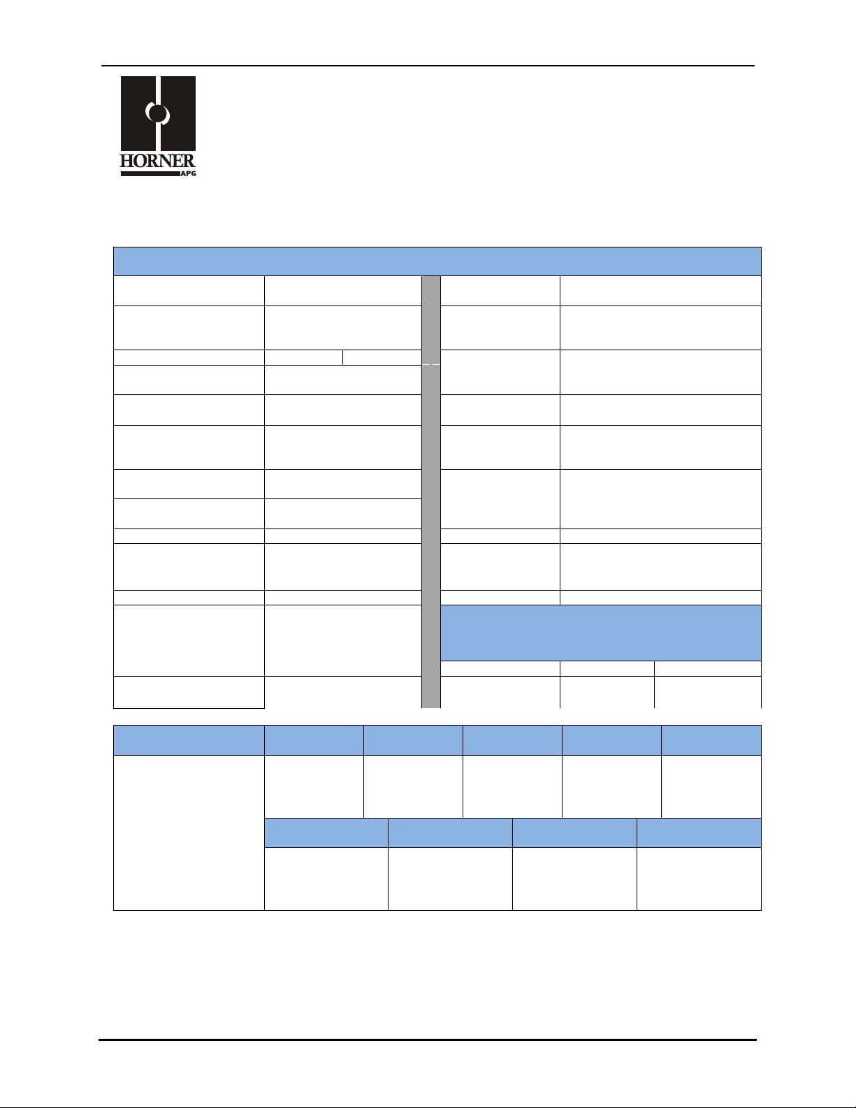
1 SPECIFICATIONS
Isolation Test Voltage
3KV
Isolation Leakage
Resistance
100 M!
Continuous Isolation
Working Voltage
565 Vpeak
Open
Thermocouple
Detect current
50 nA
Number of Channels
4 (THM100)
8 (THM200)
Thermocouple
Resolution
0.1°C
Analog Input
Points Required
8
Differential Input
Impedance
>20Meg Ohm clamped
@ ±20VDC
Cold Junction
Compensation
Internal per channel
A/D Conversion Type
24 bit Delta Sigma ("#)
Maximum
Sustained
Differential O/L
Limited by Common Mode
Range
Required Power
(Steady State)
TBDW (TBDmA @
24VDC)
Required Power
(Inrush)
TBD
Open
Thermocouple
Response
High Temperature
Types Supported
J,K,N,T,E,C,R,S,B
Relative Humidity
5 to 95% Non-condensing
Millivolt Ranges
±25mv, ±50mv,
±100mv, ±200mv
(16 bit Resolution)
Operating
Temperature
0° to 60° Celsius
Millivolt Accuracy
0.1% Full Scale
Weight
12oz/340g
Accuracy
Note: Accuracy Specifications not guaranteed below -200°C
Common Mode Range
(wrt field common)
± 10VDC Max.
Types J,K,T, E, N
Type C, B
Types R & S
A/D Conversion Time
6 channels per second
±1.8° F
(±1°C)
± 3.6° F
(±2°C)
± 3.6° F
(±2°C)
Thermocouple Type:
J K N
T
E
-210°C to
1200°C
(-346°F to
2192°F)
-270°C to
1372°C
(-454°F to
2502°F)
-270°C to
1300°C
(-454°F to
2372°F)
-270°C to
400 °C
(-454°F to
752°F)
-270°C to
1000°C
(-454°F to
1832°F)
C R S
B
Input Range
Temperature
0°C to
2320°C
(32°F to
4208°F)
0°C to
1768.1°C
(32°F to
3215°F)
0°C to
1768.1°C
(32°F to
3215°F)
0°C to
1820°C
(32°F to
3308°F)
SmartBlock I/O Module
4-Channel HE579THM100
8-Channel HE579THM200
Page 2
MAN0927-03 PAGE 2 Thermocouple module
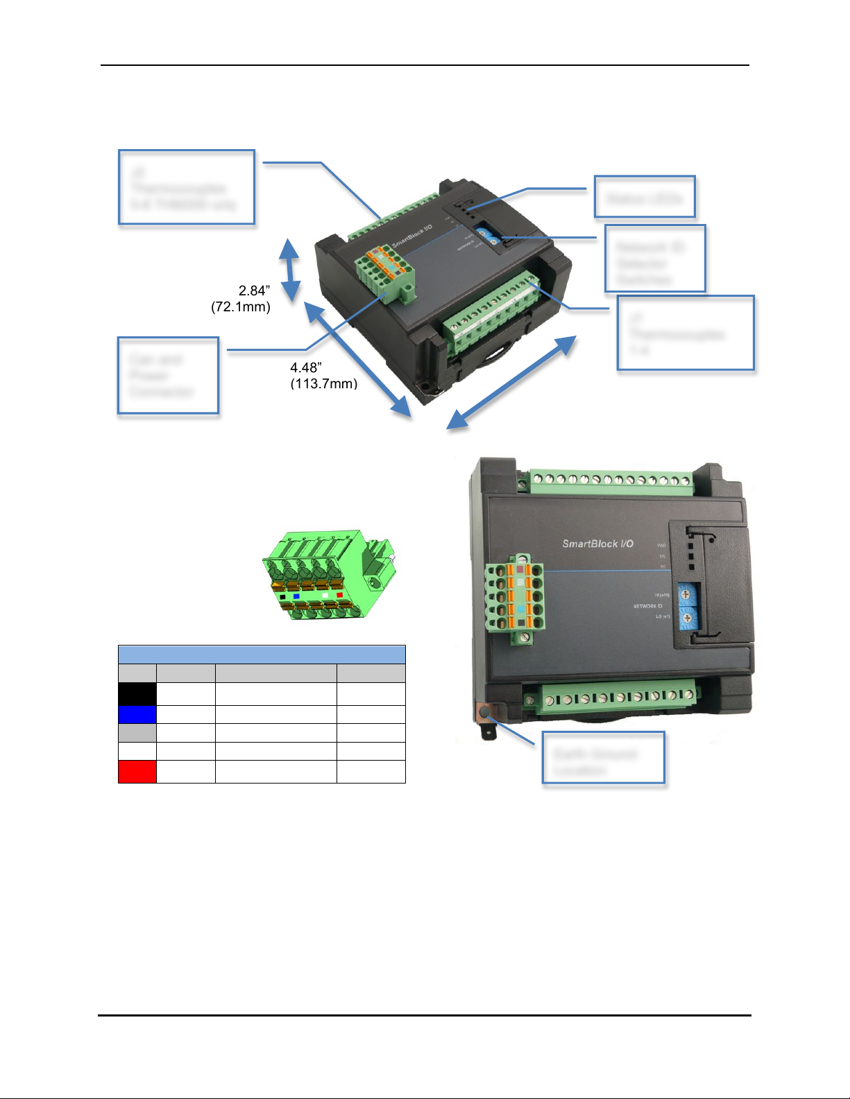
2 DIMENSIONS AND INSTALLATION
Network, Power and Grounding:
A single 5 pin connector is used to make both a network connection and power input. A quality class 2
power supply should be used for this product. If the power is run with the network cable, care must be
taken such that the voltage does not drop below the lower supply limit on longer runs.
A quality earth ground is required for safe and proper operation. The best ground is achieved by
screwing the lower left grounding location into a grounded back plate. Alternately a ground can be
connected to the spade lug.
Please see Horner manual MAN0799 for details on CAN wiring.
CAN Network & Power Port Pin Assignments
Pin
Signal
Signal Description
Direction
1
V-
CAN and Device
Ground - Black
!
2
CN_L
CAN Data Low - Blue
In/Out
3
SHLD
Shield Ground - None
!
4
CN_H
CAN Data High - White
In/Out
5
V+
Positive DC Voltage
Input (10-30VDC) - Red
!
4.56”
(115.8mm)
4.48”
(113.7mm)
2.16”
(54.8mm)
With connector
2.84”
(72.1mm)
CAN Network & Power
Connector
Torque rating 4.5 – 7 Lb-In
(0.50 – 0.78 N-m)
J2
Thermocouples
5-8 THM200 only
J1
Thermocouples
1-4
Can and
Power
Connector
Network ID
Selector
Status LEDs
Earth Ground
Location
Page 3

MAN0927-03 PAGE 3 Thermocouple module
3 WIRING
Grounded thermocouples wiring options
Field ground potential less than 7V AC. Shields connected at one end only may be used to reduce noise.
Ungrounded thermocouples wiring options
Preferred shield connection Alternate shield connection
Ungrounded thermocouples should have one side tied to isolated common to reduce noise pickup.
Grounded thermocouples may use type 3 or 4 shield connections if shield is not grounded at field end.
Type 1
Type 2
Type 3
Type 4
< 7VAC
< 7VAC
Page 4

MAN0927-03 PAGE 4 Thermocouple module
4 NETWORK DATA
Consumed Digital Data – This data is sent from the controller to the SmartBlock. For typical
applications the I/O configuration setup in Cscape will automatically populate this data. For more
advanced applications you may use NetPut functions to write this data. Please see the advanced
programming guide MAN0880 for more details.
Bit
Description
12
0 = 0.1°C 1 = 0.1°F
13-16
Filter
See programming Guide
17-20
Thermocouple Type Channel 1
21-24
Thermocouple Type Channel 2
25-28
Thermocouple Type Channel 3
29-32
Thermocouple Type Channel 4
65-68
Thermocouple Type Channel 5
69-72
Thermocouple Type Channel 6
73-80
Thermocouple Type Channel 7
77-80
Thermocouple Type Channel 8
0 = J, -210°C to 1200°C
1 = K, -200° to 1372°C
2 = N, -200°C to 1300°C
3 = T, -200°C to 400°C
4 = E, -200°C to 1000°C
5 = R, -50°C to 1768°C
6 = S, -50°C to 1768°C
7 = B, 250°C to 1820°C
8 = C, 0°C to 2320°C
12 = 25mV
13 = 50mV
14 = 100mV
15 = 200mV
Produced Analog Data – This data is sent from the SmartBlock to the controller. Normally this data is
mapped into specific registers in the I/O configuration in Cscape. For advanced applications NetGet
functions can be used to obtain this data. Since this data is broadcast to all controllers on the network
additional controllers can use NetGet functions to obtain this data as well.
Word
Function
Word 1
INT
Thermocouple Input 1
Word 2
INT
Thermocouple Input 2
Word 3
INT
Thermocouple Input 3
Word 4
INT
Thermocouple Input 4
Word 5
INT
Thermocouple Input 5 (THM200 Only)
Word 6
INT
Thermocouple Input 5 (THM200 Only)
Word 7
INT
Thermocouple Input 5 (THM200 Only)
Word 8
INT
Thermocouple Input 5 (THM200 Only)
Page 5

MAN0927-03 PAGE 5 Thermocouple module
5 INSTALLATION / SAFETY
Warning: Remove power from the OCS controller, CAN port, and any peripheral equipment
connected to this local system before adding or replacing this or any module
a) All applicable codes and standards should be followed in the installation of this product.
b) Shielded, twisted-pair wiring should be used for best performance.
c) Shields are to be terminated to frame ground.
d) In severe applications, shields should be tied directly to the ground block within the panel.
e) Ungrounded thermocouple sensors are preferred due to their isolated electrical
characteristics
f) Interposing terminal strips between the sensor and the module can cause errors due to cold
junction effect.
g) If Interposing terminal strips must be used, use specially constructed terminal blocks, which
match the material characteristics of the thermocouple sensor.
h) Horner thermocouple input modules use a high impedance differential circuit to support the
use of grounded or ungrounded thermocouples. For grounded thermocouples, the specified
Common Mode Range allows for ground potential differences between the machine ground
and the PLC ground within that range. For ungrounded or floating thermocouples the high
impedance inputs are subject to common mode noise pickup. For noisy environments it is
recommended that one side of all ungrounded thermocouples be grounded near the PLC.
This does not affect open thermocouple detection or measurement accuracy and reduces the
effect of common mode noise if present. This PLC side ground connection must not be used
with grounded thermocouples or accuracy will be affected. Any thermocouple should be
grounded in one place at most.
When found on the product, the following symbols specify:
• All applicable codes and standards need to be followed in the installation of this product.
• For I/O wiring (discrete), use the following wire type or equivalent: Belden 9918, 18 AWG or
larger.
Warning: Consult user documentation.
Warning: Electrical Shock Hazard.
WARNING: To avoid the risk of electric shock or burns, always connect the safety (or
earth) ground before making any other connections.
WARNING: To reduce the risk of fire, electrical shock, or physical injury it is strongly
recommended to fuse the voltage measurement inputs. Be sure to locate fuses as close to
the source as possible.
WARNING: Replace fuse with the same type and rating to provide protection against risk of
fire and shock hazards.
WARNING: In the event of repeated failure, do not replace the fuse again as a repeated
failure indicates a defective condition that will not clear by replacing the fuse.
WARNING: Only qualified electrical personnel familiar with the construction and operation
of this equipment and the hazards involved should install, adjust, operate, or service this
equipment. Read and understand this manual and other applicable manuals in their entirety
before proceeding. Failure to observe this precaution could result in severe bodily injury or
loss of life.
Page 6

MAN0927-03 PAGE 6 Thermocouple module
Adhere to the following safety precautions whenever any type of connection is made to the module.
• Connect the green safety (earth) ground first before making any other connections.
• When connecting to electric circuits or pulse-initiating equipment, open their related breakers.
Do not make connections to live power lines.
• Make connections to the module first; then connect to the circuit to be monitored.
• Route power wires in a safe manner in accordance with good practice and local codes.
• Wear proper personal protective equipment including safety glasses and insulated gloves
when making connections to power circuits.
• Ensure hands, shoes, and floor are dry before making any connection to a power line.
• Make sure the unit is turned OFF before making connection to terminals. Make sure all
circuits are de-energized before making connections.
• Before each use, inspect all cables for breaks or cracks in the insulation. Replace
immediately if defective.
2 TECHNICAL SUPPORT
North America:
Tel: 317 916-4274
Fax: 317 639-4279
Web: http://www.heapg.com
Email: techsppt@heapg.com
Europe:
Tel: +353-21-4321266
Fax: +353-21-4321826
Web: http://www.horner-apg.com
Email: tech.support@horner-apg.com
Cscape, SmartStix and CsCAN are trademarks of Horner APG. This information is subject to change without notice.
 Loading...