

Page 1
Quick Reference Guide for HE-RCC6512
BUILT-IN I/O: 12 DIGITAL INPUTS, 10 DIGITAL OUTPUTS, 2 ANALOG INPUTS, 4 ANALOG OUTPUTS
GETTING STARTED
1 Read this document to fully understand the
RCC6512 and safety requirements.
2 Connect 24VDC power and I/O according to
the quick start guide and datasheet.
3 Refer to the Horner website for the current
user manual [MAN1133] and datasheet
[MAN1134] for the RCC6512.
North America
http://www.hornerautomation.com
Europe
http://www.horner-apg.com
MAN1135-02-EN
1.1 General
Primary Pwr. Range 10-28VDC
Required Pwr. (Steady-State) 120mA @ 24VDC
Required Pwr. (Inrush
Current)
Real Time Clock Battery-backed
Clock Accuracy +/- 60 Secs/Month @ 24°C
Relative Humidity 5 to 95% Non-condensing
Operating Temp. -10°C to +60°C
Storage Temp. -10°C to +60°C
Weight 12.5 oz (354.37g)
Max. Altitude 2000m
Included in Box
Certifications
(UL/CE)
25A for 1ms
@ 24VDC switched
Controller,
2 x I/0 connectors,
1 x power connector,
Quick Reference Guide
USA: https://hornerautomation.
com/certifications/
Europe: http://www.horner-apg.
com/en/support/certification.
aspx
1.2 Connectivity
Serial Ports
CAN 1 x 125 kbps - 1 Mbps
Ethernet 1 x 10 Mbps/100Mbps
microSD
USB
Communication Support CsCAN, Modbus, EGD
1 x 232, 1 x RS485
(Full/Half Duplex - Sortware
Selectable)
1 x uSD, SDHC, SDXC in
FAT32 format
USB Mini-B Slave (Configuration and Application
Programming only)
1.3 User Interface / Control & Logic
Control Language Support
Logic Size & Scan Rate 16kb, 0.7ms/kB
Programming
PID Support Up to 6
Advanced Ladder Logic or
61131-3 Language
Supported in Advanced
Ladder
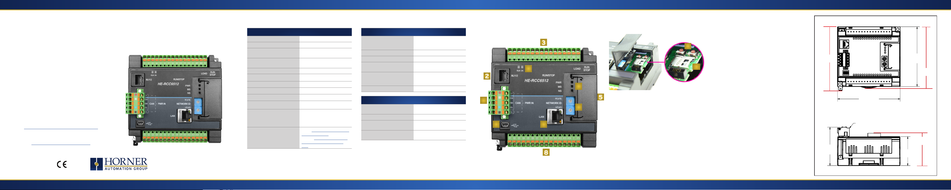
2 - Port Connectors1 - General Specifications
3
4
11
10
2
4
1
6
79
5
1. Power/CAN Connector
2. Serial Port
3. Input Connector - J2
4. Status LEDs
5. Door
6. Network ID Switches
3 - Installation Procedure
The RCC6512 conveniently mounts on a DIN
rail.
Be sure the DIN rail is in a horizontal position
before installing the unit.
The orientation shown to the right is necessary
to prevent the unit from slipping off the DIN rail.
Align the unit on the DIN rail then push the DIN
rail clip until it clicks into place. Check to ensure
that the unit is secure on the DIN rail.
Do NOT mount the unit on its side as this may
cause the unit from slipping off the DIN rail.
NOTE: The spade connector for grounding
and the DIN rail clip add to the overall
measurements. The CAN/PWR and LAN
connectors also add to the measurements.
NOTE: Screw holes and a spade connector are
available for a mounting option.
RCC6512 DIMENSIONS
4.48”
113.7mm
4.57”
4.57
116mm
CONNECTOR
4.37”
111mm
4.37
4.67”
118.6mm
7. Ethernet Port
8
8. Output Connector -J1
9. Mini USB Port
10. microSD Slot
11. LOAD / RUN|STOP
buttons
2.81
2.81”
72mm
2.13
2.13”
54mm
2.33”
59.25mm
Indianapolis, USA | Cork, Ireland | Calgary, Canada | Bangalore, India | Oakleigh, Australia | Tianjin, China | Esteio, Brazil Please visit our website for a complete listing and to learn more about certified Horner Automation products. This document is the property of Horner Automation Group and is subject to change.
Page 2
4 - Warnings
Precautions
All applicable codes and standards need to be followed in the
installation of this product. Adhere to the following safety
precautions whenever any type of connection is made to the
module:
1. Connect the safety (earth) ground on the power connector
first before making any other connections.
2. When connecting to the electric circuits or pulse-initiating
equipment, open their related breakers.
3. Do NOT make connection to live power lines.
4. Make connections to the module first; then connect to the
circuit to be monitored.
5. Route power wires in a save manner in accordance with
good practice and local codes.
6. Wear proper personal protective equipment including
safety glasses and insulted gloves when making
connections to power circuits.
7. Ensure hands, shoes, and floor are dry before making any
connection to a power line.
8. Make sure the unit is turned OFF before making
connection to terminals.
9. Make sure all circuits are de-energized before making
connections.
10. Before each use, inspect all cables for breaks or cracks in
the insulation. Replace immediately if defective.
11. Use copper conductors in Field Wiring only, 60/75˚ C.
12. Do not disconnect while circuit is live unless area is known
to be non-hazardous.
13. Do not remove or replace jumpers or connectors while
circuit is live unless the area is known to be free of
ignitable concentrations of flammable gases or vapors.
14. EXPLOSION HAZARD – substitution of components may
impair suitability for Class I, Division 2.
15. Use caution when making connections to the controller
to protect against static discharge. Special care must be
taken when replacing the battery or inserting or adjusting
I/O or communication boards.
16. Use caution when connecting controllers to PCs via serial
or USB. PCs and especially laptops may use “floating
power supplies” what are ungrounded. This could cause
a voltage potential between the laptop and controller.
Make sure the controller and laptop are grounded for
maximum protection.
17. For protection of USB devices the part number HE-USBISO
is available to purchase from our website or your local
distributor.
18. Failure to follow these guidelines can damage the
controller and/or controller.
Hazardous Location Notice
Power, input and output (I/O) wiring must be in accordance
with Class 1, Division 2 wiring methods [Article 501-4(b) of the
National Electrical Code, NFPA 70] for installations in the U.S. or
as specified in Section 18-1J2 of the Canadian Electrical Code for
installations within Canada and in accordance with the authority
having jurisdiction.
1. THIS EQUIPMENT IS SUITABLE FOR USE IN CLASS I,
DIVISION 2, GROUPS A, B, C & D HAZARDOUS or NON-
HAZARDOUS LOCATIONS ONLY.
2. WARNING – EXPLOSION HAZARD – DO NOT DISCONNECT
EQUIPMENT UNLESS POWER HAS BEEN SWITCHED OF OR
THE AREA IS KNOWN TO BE NON-HAZARDOUS.
AVERTISSEMENT - RISQUE D’EXPLOSION -NE DECONNECTEZ PAS
L’EQUIPEMENT A MOINS QUE L’ALIMENTATION AIT ETE COUPEE
OU QUE LA ZONE NE SOIT PAS DANGEREUSE.
3. DEVICES SHALL BE INSTALLED INTO AN ENCLOSURE
THAT IS ONLY ACCESSIBLE WITH THE USE OF A TOOL.
FCC Compliance
This device complies with part 15 of the FCC
Rules. Operation is subject to the following
two conditions:
1. This device may not cause harmful interference
2. This device must accept any interference received,
including interference that may cause undesired
operation
Technical Support
For further details, please refer to the Datasheet, MAN1134. For
assistance and manual updates, contact Technical Support at the
following locations:
North America Europe
+1 (317) 916-4274 +353 (21) 4321-266
www.hornerautomation.com www.horner-a pg.com
techsppt@ heapg .com technical.support@horner-apg.com
5 - Connecting the RCC6512 to a PC
The RCC6512 can communicate with Cscape using USB to USB, USB
to serial adapters, serial port communications via MJ1 Port, CAN
(CsCAN), or Ethernet.
To communicate with the RCC6512 via USB, you will need the
Automated Driver Installer located on our website. The drivers may
be loaded from the HE-XEC Ethernet Utility -> HTTP Web Server
Demo -> Communications Driver section of the support files page
found at : https://hornerautomation.com/support-files .
Next, connect a PC’s (Personal Computer running a Windows
Microsoft operating system) USB port via USB cable to the USB mini
B port on the RCC6512.
Now that the RCC6512 is plugged in, go to the Cscape menu
Controller -> Connection Wizard, choose your connection
method. If you’re connecting for the first time, we suggest
connecting via USB.
If communication is established, the target indicator will show
the mode of the controller Target: yy(R).
If the controller is not communicating, you may need to set the
Target ID of the controller in Cscape or change the controllers ID
on the unit itself. The Target ID allows directing communications
to a particular unit when multiple units are connected via a
CsCAN network. Units without CsCAN network ports respond
to any network ID and do not require the ID to be configured.
For more information, review the Cscape Configuration chapter
of the RCC6512 User Manual, MAN1133.
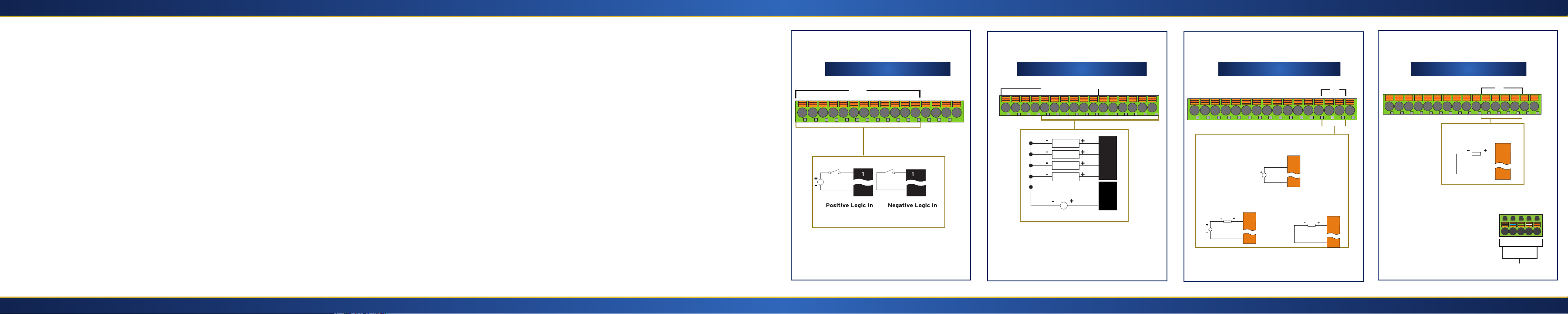
6.1 - Wiring Connectors: Digital In
J2 Wiring - Digital Input J1 Wiring - Digital Output J2 Wiring - Analog Input J1 Wiring - Analog Output
I1 I2 I3 I4 I5 I6 I7 I8 I9 I10 I11 I12 C AI2 AI1 C
DI
V-
-5 to +24VDC
V-
6.2 - Wiring Connectors: Digital Out 6.3 - Wiring Connectors: Analog In 6.4 - Wiring Connectors: Analog Out
Q1 Q2 Q3 Q4 Q5 Q6 Q7 Q8 Q9 Q10 AQ1 AQ2 AQ3 AQ4 C V1+
DO
LOAD
LOAD
LOAD
LOAD
10-28VDC
Q1
Q2
Q3
Q4...
C
V1+
I1 I2 I3 I4 I5 I6 I7 I8 I9 I10 I11 I12 C AI2 AI1 C
0 - 10V Analog In
AI
0 - 10 V
4 - 20mA Analog In
Loop Power Required
AI
C
C
4 - 20mA Analog In
No Loop Power
Required
AI
AI
C
Q1 Q2 Q3 Q4 Q5 Q6 Q7 Q8 Q9 Q10 AQ1 AQ2 AQ3 AQ4 C V1+
+/- 10V Analog Out
6.5 - Wiring Connectors: Power
To power up the RCC6512, supply
10-28VDC to the V- and V+
connections on the Power/CAN
Analog Connector.
AO
AQ
C
V- CL SH CH V+
CAN
PWR IN
Indianapolis, USA | Cork, Ireland | Calgary, Canada | Bangalore, India | Oakleigh, Australia | Tianjin, China | Esteio, Brazil Please visit our website for a complete listing and to learn more about certified Horner Automation products. This document is the property of Horner Automation Group and is subject to change. Indianapolis, USA | Cork, Ireland | Calgary, Canada | Bangalore, India | Oakleigh, Australia | Tianjin, China | Esteio, Brazil
 Loading...