

Page 1
Fiber Optic Extension System
HE800FOX104 / FOX404
Products Specifications
and Installation Data
For detailed installation, configuration and other information, refer to the hardware manual of the
controller you are using. See the Additional References section in this document.
1 SPECIFICATIONS
Table 1 – FOX104 / FOX404
Maximum number of stacks (total
number of hubs and bases)
Maximum number of cable drops to
any specific hub or base
Maximum length of Fiber Optic cable 10 Meters per Drop
Base ID# Each Base or Hub must have a unique Base ID #.
Expansion I/O
Type of Fiber Optic Cable EIAJ RC-5720 (RC)
Primary Power 9-30VDC @ 400mA maximum
Power Draw 9-30VDC @ 400mA maximum
Height 4.25” (108 mm)
Width 6.63” (168.3 mm)
Mounting Depth 4.7” (119.4 mm)
Operating Temperature
Humidity 5% to 95% non-condensing
UL Class I, Groups A, B, C, D, Division 2
CE Yes
EIAJ RC-5720 Plastic Fiber, TX+RX 10m per drop max host (OCS or
3 (See Section Six for Example Setups)
32 - 122°F (0 - 50°C)
5
hub) to base
2 INSTALLATION
2.1 Mounting Orientation
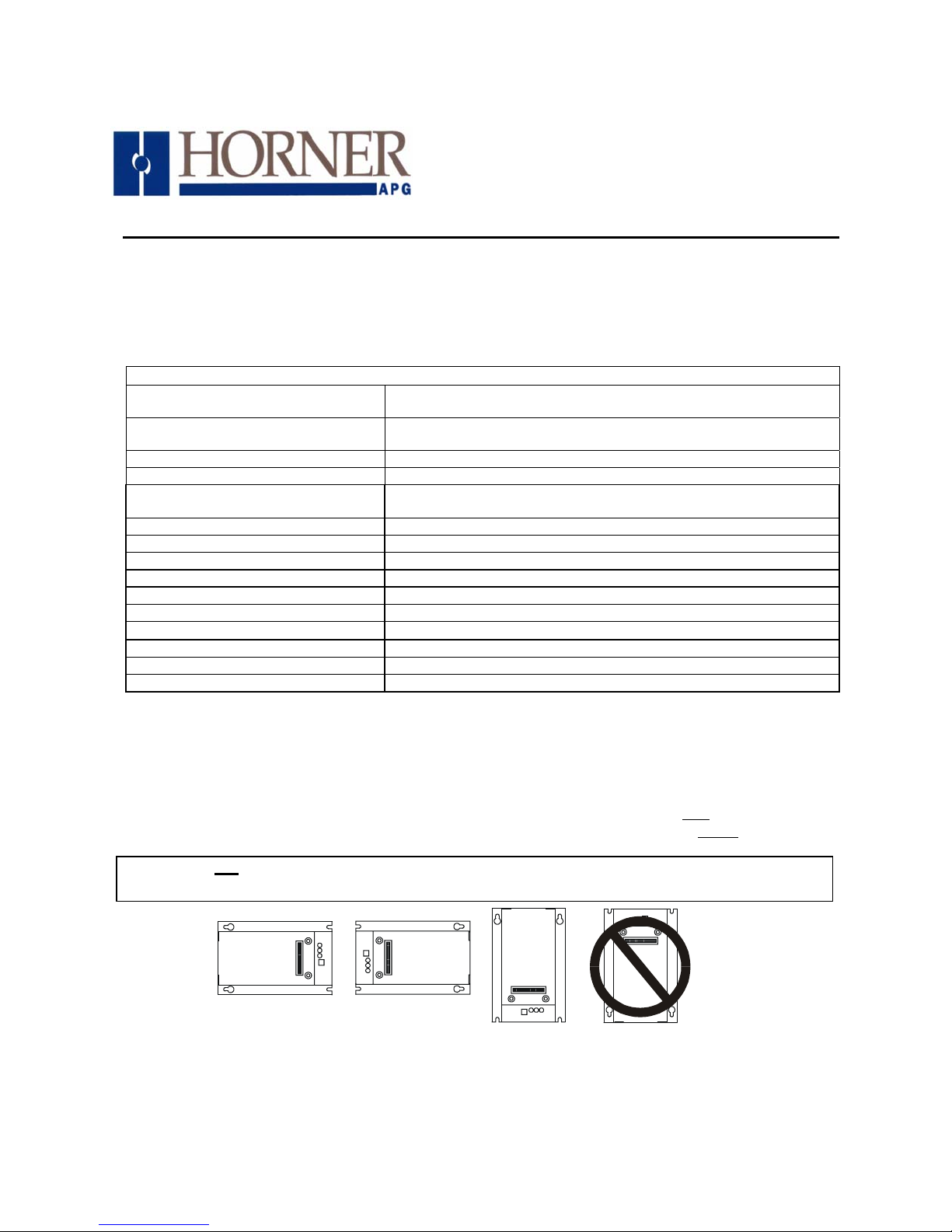
The base of the FOX104 / FOX404 need to be mounted with the proper orientation. Proper orientation
helps to ensure a good connection when SmartStack Modules are installed. Up to four
Modules can be installed per FOX104 / FOX404. The FOX104 / FOX404 is installed inside
Caution: Do not instack more than four SmartStack Modules per OCS/RCS/FOX. Improper
operation or damage to the OCS/RCS/FOX and SmartStack Modules could result.
001FOX006
Figure1 – FOX104 / FOX404 Orientation
08 June 2005 MAN0508-03
SmartStack
a panel box.
Page 2
PAGE 2 08 JUN 2005 MAN0508-03
2.2 Mounting Instructions (Back Plane / DIN-Rail)
There are two ways to mount the FOX104 / FOX404 in a panel box. It can either be hard-mounted to the
back plane or mounted on a DIN-Rail strip.
a. Back Plane Mounting
1. Read the Installation Chapter in the hardware manual of the controller you are using prior
to
mounting the FOX104 / FOX404. Observe requirements for the panel layout design and
adequate clearances. A checklist is provided for your convenience in the hardware manual. (See
the Additional References section in this document.)
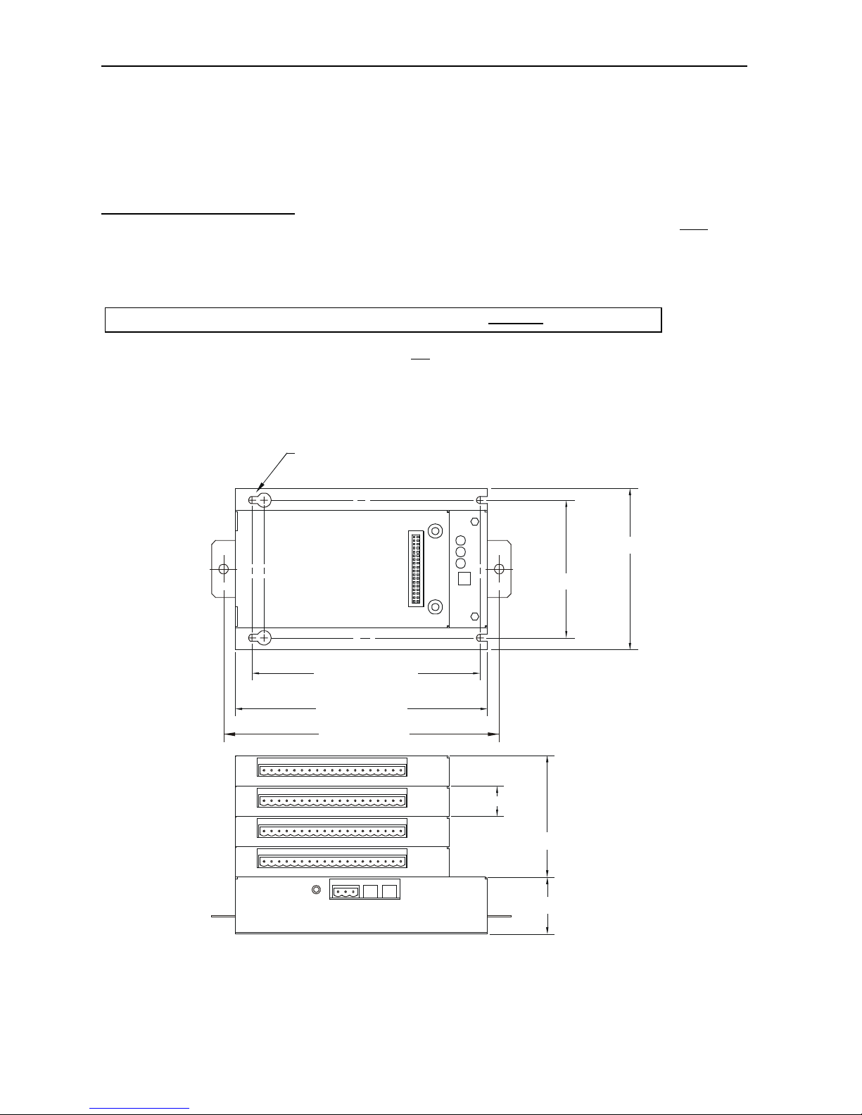
2. Drill holes. (Refer to Figure 2.)
Warning: Make sure the power and network connectors are removed from the FOX.
3 Install and tighten washers and nuts. Do not
over-tighten.
4. Connect the communications and power cables to the FOX104 / FOX404 ports using the
provided connectors.
5. Install up to four SmartStack Modules on the FOX104 / FOX404.
2.3 Dimensions and Hole Pattern
MOUNTING HOLES FOR #8 OR M4 HARDWARE
4.25 [108.0mm]
3.625 [92.08mm]
6.000 [152.40mm]
6.63 [168.3mm]
7.87 [200.0mm]
0.80 [20.3mm]
3.20 [81.3mm]
1.50 [38.1mm]
NOTE: Use #8-32 or M4 mounting hardware consisting of four pan head screws with external tooth lock washers.
001FOX001-R1
Figure 2 – FOX104/404 Hole Pattern (Top) and Viewed with 4 SmartStack I/O Modules (Bottom)
Page 3
MAN0508-03 08 JUN 2005 PAGE 3
b. DIN-Rail Mounting
1. Read the Installation Chapter in the hardware manual of the controller you are using prior
to
mounting the FOX104 / FOX404. Observe requirements for the panel layout design and
adequate clearances. A checklist is provided for your convenience in the hardware manual. (See
the Additional References section in this document.)
2. Determine length of DIN-Rail needed. (Refer to Figure 2.)
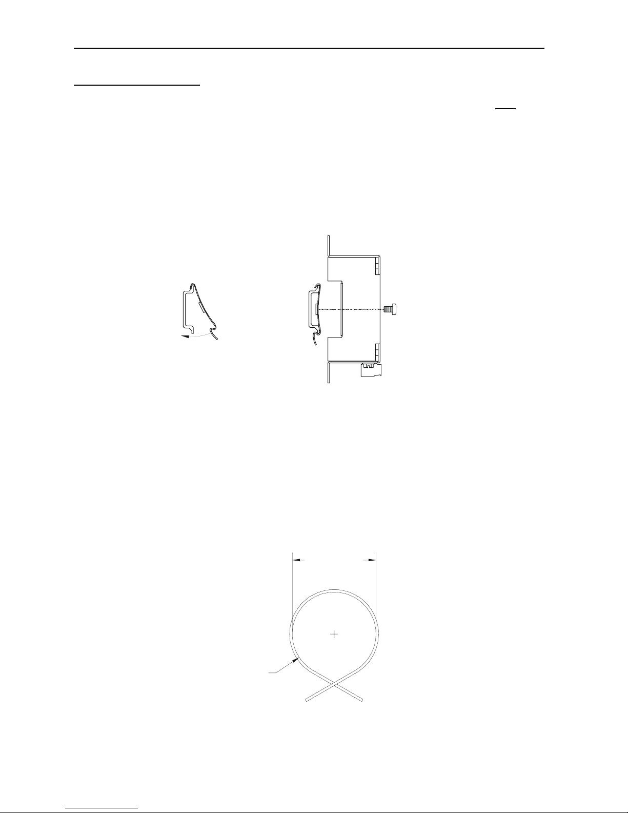
3. Noting the proper location, attach two (2) DIN-Rail mounting clips (included with FOX unit) to the
DIN-Rail by hooking the clips over the top of the Rail and rocking down and snapping over the
bottom of the Rail. (Refer to Figure 3.)
4. Adjust clips as necessary by sliding them along the DIN-Rail to align with the holes in the tabs of
the FOX unit. Using the provided screws, mount the Fox unit to the clips. Tighten screws as
necessary to hold the unit securely. (Refer to Figure 3.)
FOX104 /
FOX404
DIN-Rail
Mounting
Clips
Close-up of mounting clips
being hooked on to DIN-rail.
001FOX012
Figure 3 – (Left) DIN-Rail and Mounting Clips, and (Right) FOX104 / FOX404 DIN-Rail Mounting
2.4 Fiber Optic Cable Installation
Important considerations for installing the FOX include the following guidelines:
a. To ensure reliable communication between the FOX base and OCS/RCS module, high quality
cables need to be installed. See Table 2 for fiber cable part numbers.
b. The maximum fiber optic cable distance is 10 meters between drops.
c. During installment of the fiber optic cable, all direction changes need to adhere to a Minimum
Bend Radius of one inch (25.44mm).
2.00” (50.8mm)
Min. Diameter
1.00” (25.4mm) Min.
Bend Radius
001FOX011
Figure 3 – Fiber Optic Cable Bend Radius
Page 4
PAGE 4 08 JUN 2005 MAN0508-03
r
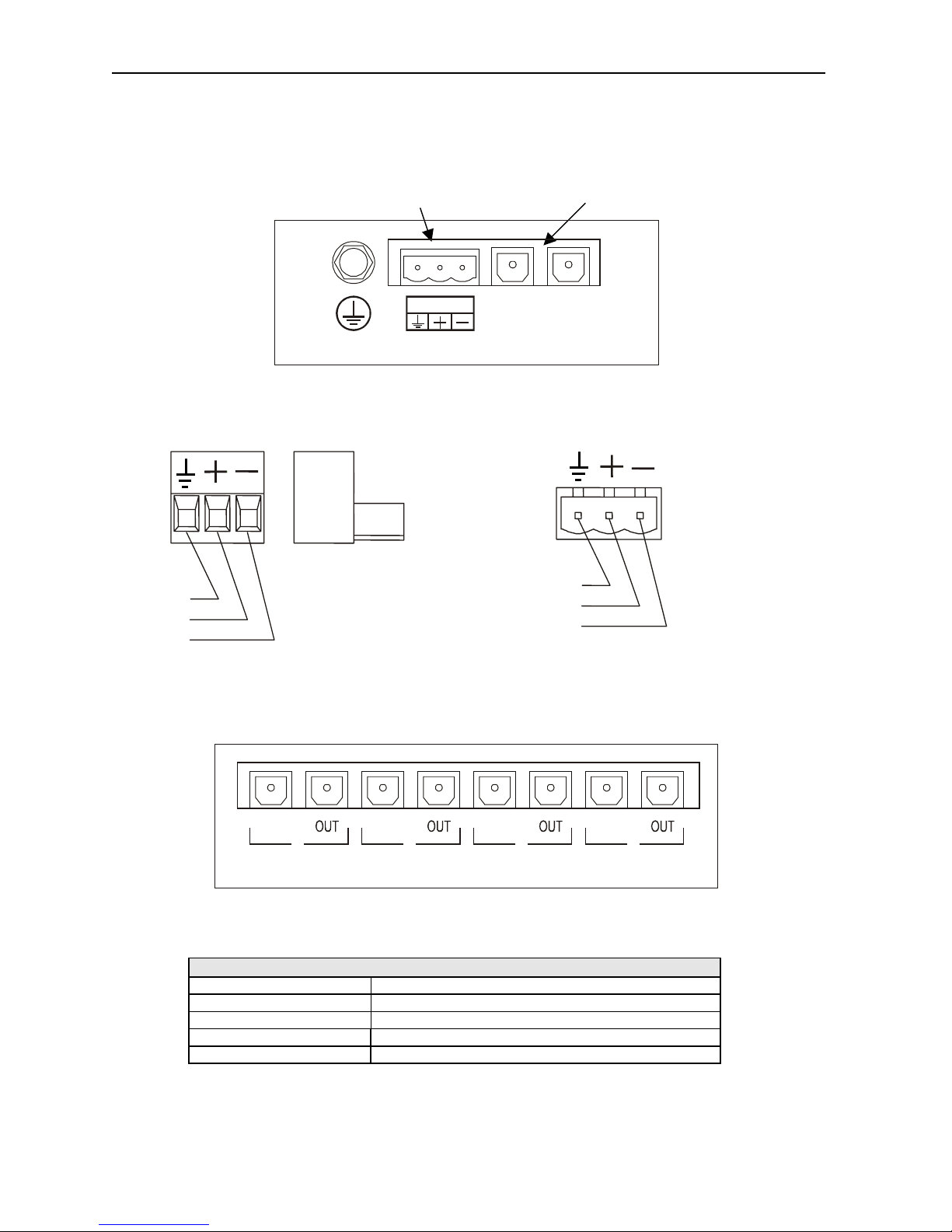
3 Ports, Connectors, and Wiring
Powe
Connection
24VDC
FROM OCS/HUB
Figure 4 – FOX104 / FOX404 Connectors
PIN 1
PIN 2
PIN 3
Figure 5 - FOX Power Connector Figure 6 - FOX Power Connector
Note: Power Supply Voltage Range is from 10-30 VDC.
IN
1234
TO REMOTE BASE
Figure 7 – FOX404
Table 2 – Fiber Optic Cables
Feet (Meters) Part Number
3.3 ft. (1 m) HE800CBF001
6.6 ft. (2 m) HE800CBF002
16.4 ft. (5 m) HE800CBF005
32.8 ft. (10 m) HE800CBF010
Host Fiber Optic
OUT
PIN 1
PIN 2
PIN 3
Connection
IN
001FOX003-R1
INININ
001FOX004
Page 5
MAN0508-03 08 JUN 2005 PAGE 5
4 Base ID Switches
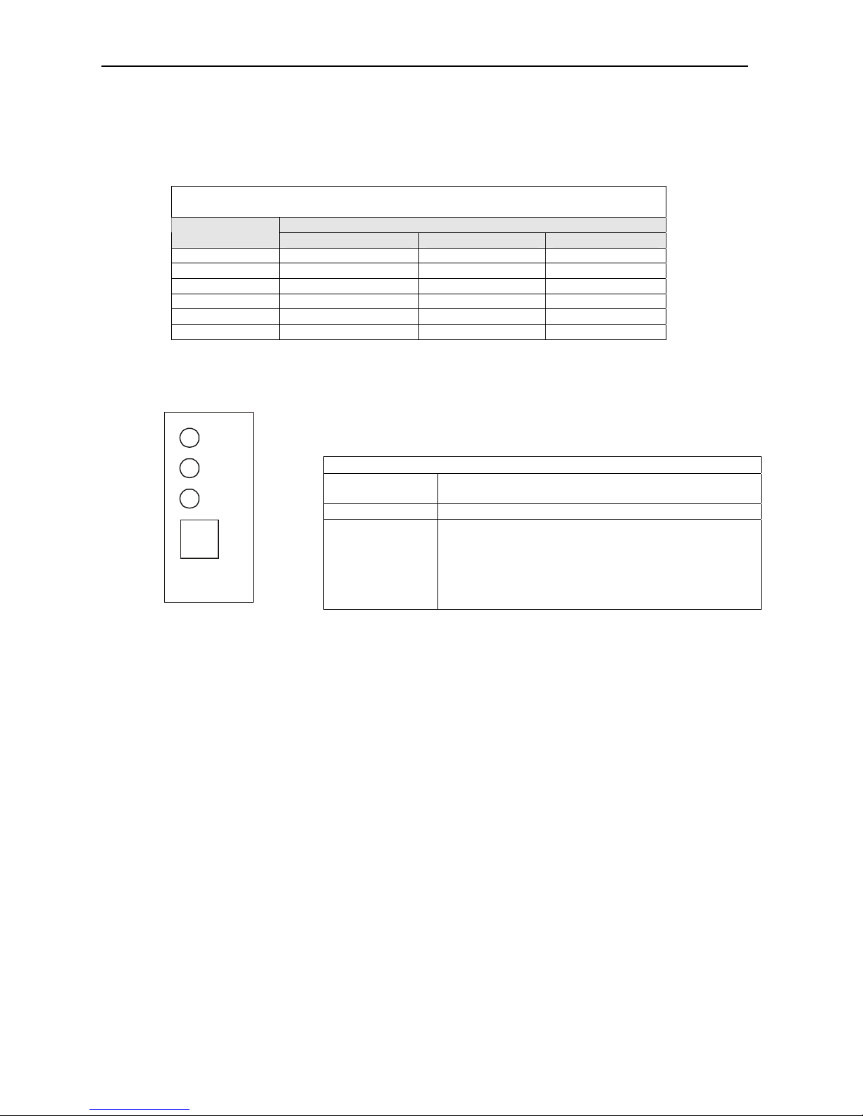
Each FOX104 / FOX404 needs a unique Base ID. (Refer to Figure 7 for location of Base ID Switches.)
Set Base ID switches using the following table.
Table 3 - Base ID Switches
ON = 1 | OFF = 0
Switch Number Base
ID
Illegal 0 0 0
1 0 0 1
2 0 1 0
3 0 1 1
4 1 0 0
5 1 0 1
4 2 1
5 FOX104 / FOX404 LEDs
Figure 8– FOX104 / FOX404 LEDs
FIBER
OK
RUN
PWR
1
2
4
OFF ON
BASE I.D.
001FOX005
Table 4 – FOX104 / FOX404 LEDs
FIBER OK ON indicates FOX’s fiber input cable is properly
connected and is receiving a carrier.
PWR ON indicates FOX is receiving power.
RUN
• OFF indicates OCS is in IDLE/STOP mode or no
power to the FOX or one of the fiber cables are
detached or there is a configuration mismatch.
• Flashing indicates DO / IO mode or RUN with no
ladder program.
• ON indicates ladder code running.
Page 6
PAGE 6 08 JUN 2005 MAN0508-03
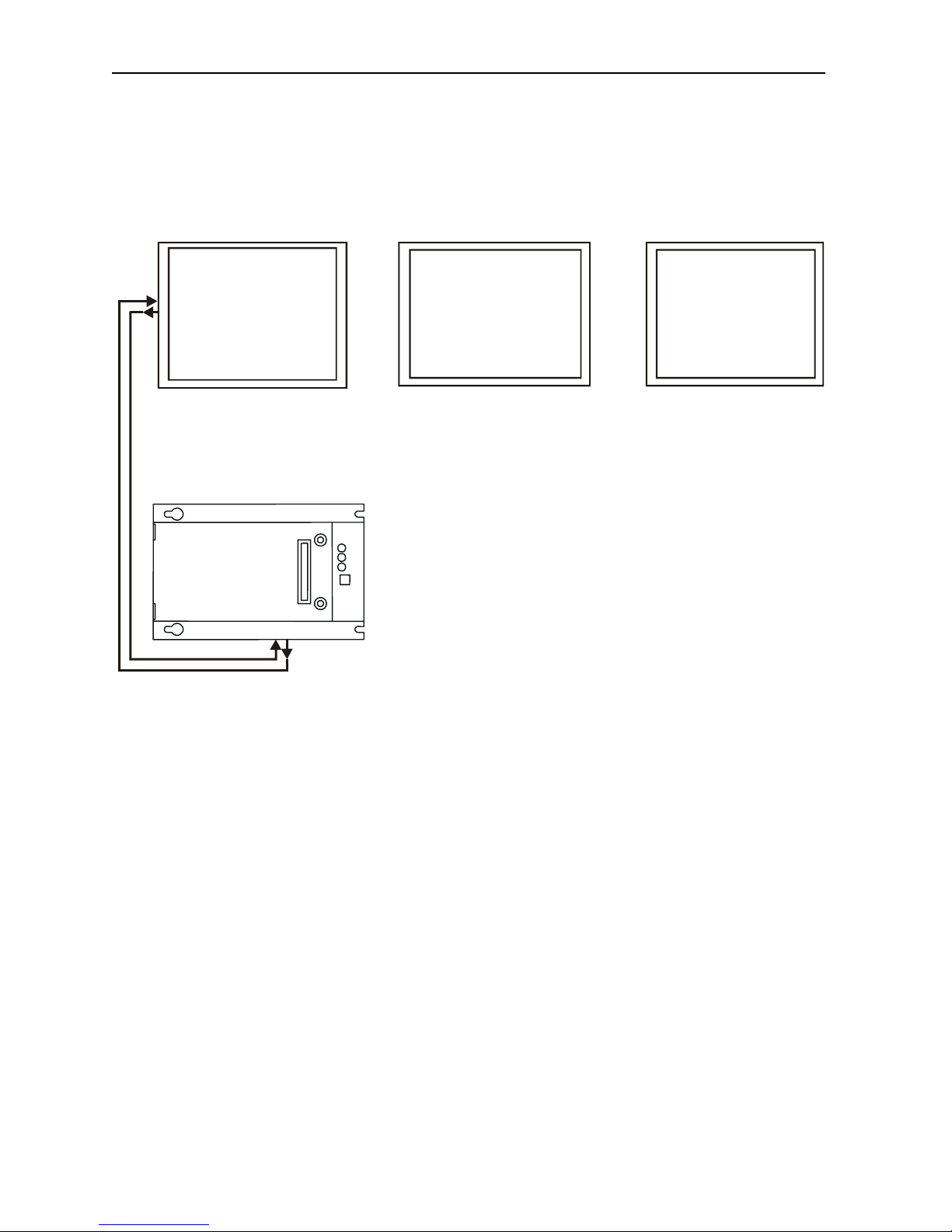
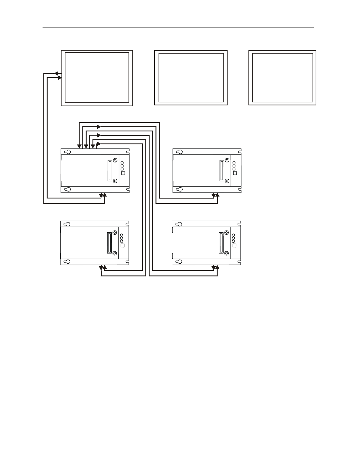
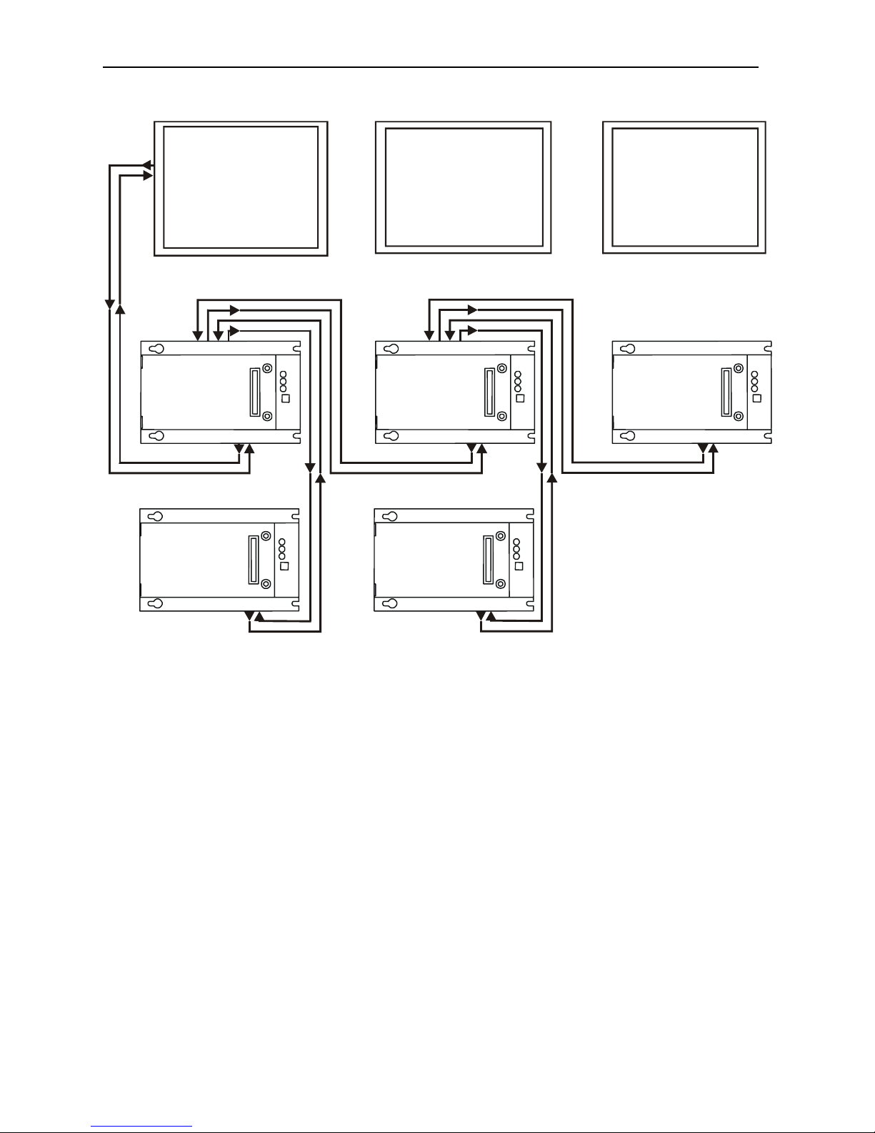
6 Example Setups
Note: The following examples depict the FOX100, but they also apply to the FOX110.
Color-Touch
OCS
4 3 2 1
HUB
FOX404
HOST
Figure 9 – OCS/RCS to FOX404 (Single Hub) via FOX100
(Or)
001OCS010-R2
Using FOX100:
OCS110,OCS210,
Graphic OCS
(OCS250)
Using FOX100:
(Or)
RCS250
Page 7
MAN0508-03 08 JUN 2005 PAGE 7
Color-Touch
(Or)
OCS
4 3 2 1
HUB
FOX404
HOST
FOX104
HOST HOST
Figure 10– OCS/RCS to FOX (One Hub [FOX404] and Multiple Bases [FOX104])
Using FOX100:
OCS110,OCS210,
Graphic OCS
(OCS250)
FOX104
HOST
FOX104
001OCS012-R2
via FOX100
Using FOX100:
(Or)
RCS250
Page 8
PAGE 8 08 JUN 2005 MAN0508-03
Color-Touch
(Or)
OCS
4 3 2 1
Figure 11 – OCS/RCS to FOX (Multiple Hubs [FOX404] and Bases [FOX104])
HUB
FOX404
HOST HOST
FOX104 FOX104
HOST HOST
Using FOX100:
OCS110,OCS210,
Graphic OCS
(OCS250)
4 3 2 1
HUB
FOX404
HOST
via FOX100
Using FOX100:
(Or)
RCS250
FOX104
001OCS011-R2
Page 9
MAN0508-03 08 JUN 2005 PAGE 9
7 SAFETY
When found on the product, the following symbols specify:
WARNING: To avoid the risk of electric shock or burns, always connect the safety (or earth)
ground before making any other connections.
WARNING: To reduce the risk of fire, electrical shock, or physical injury it is strongly
recommended to fuse the voltage measurement inputs. Be sure to locate fuses as close to the
source as possible.
WARNING: Replace fuse with the same type and rating to provide protection against risk of
fire and shock hazards.
WARNING: In the event of repeated failure, do not replace the fuse again as a repeated failure
indicates a defective condition that will not
WARNING: Only qualified electrical personnel familiar with the construction and operation of
this equipment and the hazards involved should install, adjust, operate, or service this
equipment. Read and understand this manual and other applicable manuals in their entirety
before proceeding. Failure to observe this precaution could result in severe bodily injury or
loss of life.
For detailed installation and a handy checklist
clearances, refer to the hardware manual of the controller you are using. (See the Additional
References section in this document.)
• All applicable codes and standards need to be followed in the installation of this product.
• For I/O wiring (discrete), use the following wire type or equivalent: Belden 9918, 18 AWG or
Adhere to the following safety precautions whenever any type of connection is made to the module.
• Connect the green safety (earth) ground first before making any other connections.
• When connecting to electric circuits or pulse-initiating equipment, open their related breakers. Do
• Make connections to the module first; then connect to the circuit to be monitored.
• Route power wires in a safe manner in accordance with good practice and local codes.
• Wear proper personal protective equipment including safety glasses and insulated gloves when
• Ensure hands, shoes, and floor are dry before making any connection to a power line.
• Make sure the unit is turned OFF before making connection to terminals. Make sure all circuits
• Before each use, inspect all cables for breaks or cracks in the insulation. Replace immediately if
Warning: Consult user documentation.
clear by replacing the fuse.
that covers panel box layout requirements and minimum
larger.
make connections to live power lines.
not
making connections to power circuits.
are de-energized before making connections.
defective.
Warning: Electrical Shock Hazard.
Page 10

PAGE 10 08 JUN 2005 MAN0508-03
8 ADDITIONAL REFERENCES
The following table indicates the hardware manual numbers for the controller you are using. Hardware
manuals contain detailed installation, configuration and other pertinent information. See the Technical
Support section in this document for the web site address to download references and obtain revised
editions.
Additional References
Controller Manual Number
OCS NX Series Hardware
e.g. HE-NX220, HE-NX221, HE-NX250, HE-NX251
Operator Control Station Hardware (OCS, OCX)
e.g., OCS1XX / 2XX; Graphic OCS250
Remote Control Station Hardware (RCS [except
RCS116], RCX)
e.g., RCS210, RCS250
Color Touch OCS Hardware
e.g., OCS300, OCS301,OCS350, OCS351
e.g., OCS451, OCS551, OCS651
OCS LX Series Hardware
e.g., LX280 / LX300; RCS116
MiniOCS / MiniRCS / MiniOCX / MiniRCX Hardware
e.g., HE500OCSxxx
MAN0781
MAN0227
MAN0465
MAN0755
MAN0305
Other Useful References
Cscape Programming and Reference MAN0313
DeviceNet™ Implementation
Wiring Accessories and Spare Parts Manual MAN0347
SUP0326
9 TECHNICAL SUPPORT
For assistance and manual updates, contact Technical Support at the following locations:
North America:
(317) 916-4274
www.heapg.com
email: [email protected]
Europe:
(+) 353-21-4321-266
www.horner-apg.com
email: [email protected]
 Loading...