

Page 1
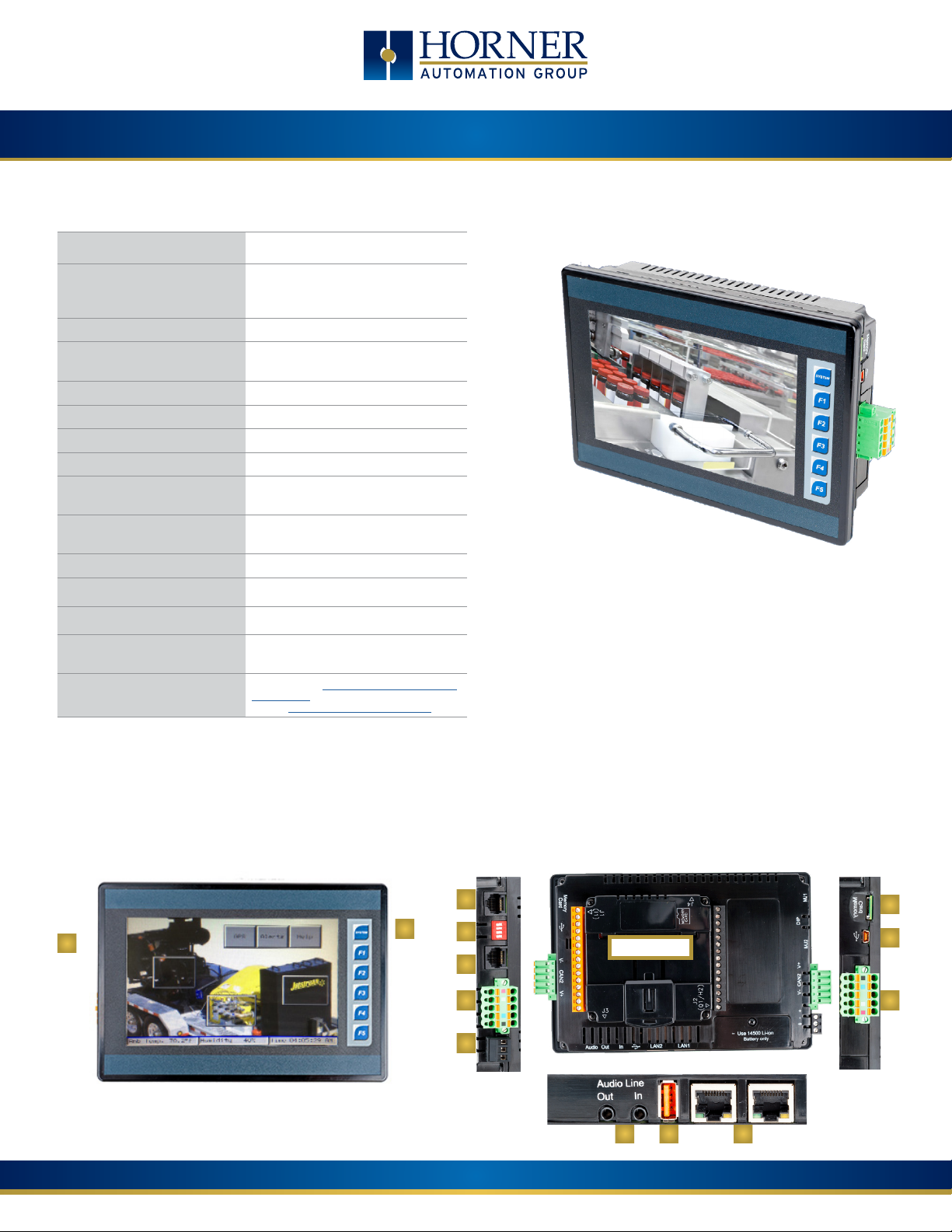
XL7 OCS QUICK START GUIDE
General Specifications
Required Power (Steady State) 170mA @ 24VDC
Heater Option
Required Power (Inrush) 7A for < 1ms @ 24VDC, DC switched
Primary Power Range 10 - 30VDC
Typical Power Backlight 100% 4.848W @ 24VDC
Power Backlight @ 50% 3.792W @ 24VDC
Power Backlight OFF 3.408W @ 24VDC
Relative Humidity 5 to 95% non-condensing
Clock Accuracy
Surrounding Air Temp
Storage Temp -20°C to +60°C
Weight 2 lbs (907g)
Altitude Up to 2000m
Rated Pollution Degree
Certifications
(UL/CE)
250mA @ 24VDC with heater operation
*Heater Option (Model # plus “-22)
+ / - 20 ppm maximum at 25°C
(+/- 1 min/month)
-10°C to +60°C (-22 Heater Option
Range is -40°C to +60°C)
Evaluated for Pollution Degree 2
Rating
North America: https://hornerautomation.com/
certifications/
Europe: http://www.hornerautomation.eu+
1. Touchscreen
2. Function Keys
3. MJ1: RS232/ MJ2: 1/2 duplex RS485
4. Dip Switches
5. MJ3: RS-232/485 Serial Port
6. CAN1 Port
7. PWR: 10-30VDC In
8. Audio In & Out Ports
9. USB 2.0 “A”: Flash Drive
10. LAN 1 & 2 Ports
11. CAN2 Port
12. USB mini “B”: Programming
13. microSD: Data Storage
XL7 Overview
NOTE: See Precaution #15 on page 4 about USB and grounding.
3
1
2
4
5
6
7
page 1 of 4
Indianapolis, USA | Cork, Ireland | Calgary, Canada | Bangalore, India | Oakleigh, Australia | Tianjin, China | Esteio, Brazil
Please visit our website for a complete listing and to learn more about certified Horner Automation products.
This document is the property of Horner Automation Group, and is subject to change.
Built-in I/O
8 9 10
13
12
11
MAN1195-02-EN
Page 2
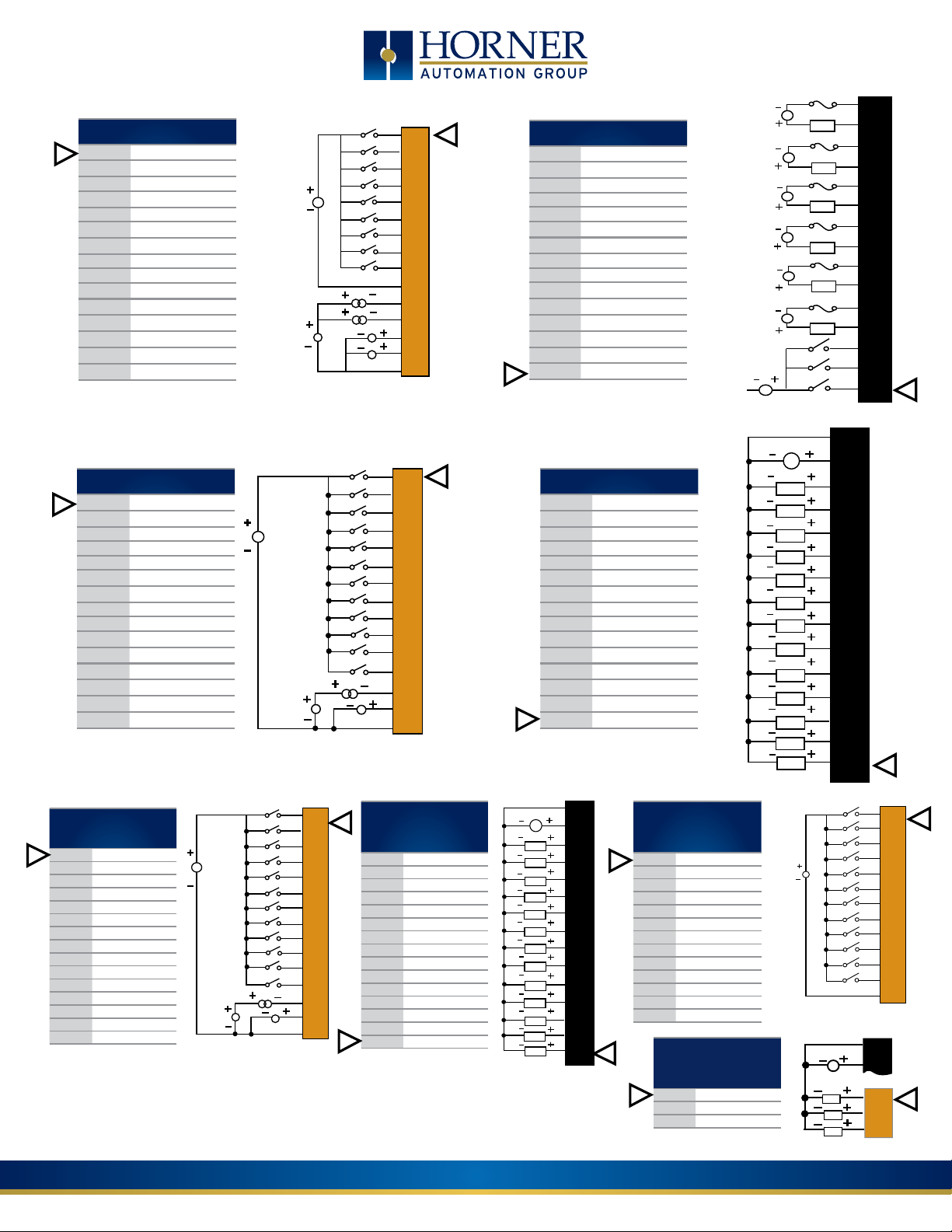
J1 (Orange)
Digital & Analog In
I1 IN1
I2 IN2
I3 IN3
I4 IN4
I5 IN5
I6 IN6
I7 IN7
I8 IN8
H1 HSC1 / IN9
0V Common
A1 Analog IN1
A2 Analog IN2
A3 Analog IN3
A4 Analog IN4
0V Common
MODEL 2: 2 DC In, 6 Relay Out, 4 – 12-bit Analog In
J2 (Black) Relay Out /
Digital In
C6 Relay 6 COM
R6 Relay 6 NO
C5 Relay 5 COM
R5 Relay 5 NO
C4 Relay 4 COM
R4 Relay 4 NO
C3 Relay 3 COM
R3 Relay 3 NO
C2 Relay 2 COM
R2 Relay 2 NO
C1 Relay 1 COM
R1 Relay 1 NO
H4 HSC4 / IN12
H3 HSC3 / IN11
H2 HSC2 / IN10
12-24VDC
LOOP PWR
20mA
0-10VDC
I1
I2
I3
I4
I5
I6
I7
I8
H1
0V
A1
A2
A3
A4
OV
0V on J1
230VAC
or
25VDC
230VAC
or
25VDC
230VAC
or
25VDC
230VAC
or
25VDC
230VAC
or
25VDC
230VAC
or
25VDC
12-24VDC
LOAD
LOAD
LOAD
LOAD
LOAD
LOAD
C6
R6
C5
R5
C4
R4
C3
R3
C2
R2
C1
R1
H4
H3
H2
J1 (Orange) Digital &
Analog In
I1 IN1
I2 IN2
I3 IN3
I4 IN4
I5 IN5
I6 IN6
I7 IN7
I8 IN8
H1 HSC1 / IN9
H2 HSC2 / IN10
H3 HSC3 / IN11
H4 HSC4 / IN12
A1 Analog IN1
A2 Analog IN2
0V Common
J1 (Orange) Name
Digital & Analog In
I1 IN1
I2 IN2
I3 IN3
I4 IN4
I5 IN5
I6 IN6
I7 IN7
I8 IN8
H1 HSC1 / IN9
H2 HSC2 / IN10
H3 HSC3 / IN11
H4 HSC4 / IN12
A1 Analog IN1
A2 Analog IN2
0V Common
MODEL 3: 12 DC In, 12 DC Out, 2 – 12-bit Analog In
J2 (Black) Positive Logic
Digital Out
0V Common
V+ V+
NC No Connect
Q12 OUT 12
Q11 OUT 11
Q10 OUT 10
Q9 OUT 9
Q8 OUT 8
Q7 OUT 7
Q6 OUT 6
Q5 OUT 5
Q4 OUT 4
Q3 OUT 3
Q2 OUT 2 / PWM 2
Q1 OUT 1 / PWM 1
12-24VDC
20mA
LOOP
PWR
0-10VDC
I1
I2
I3
I4
I5
I6
I7
I8
H1
H2
H3
H4
A1
A2
OV
10 - 30VDC
MODEL 4: 24 DC In, 16 DC Out, 2 – 12-bit Analog In
LOAD
LOAD
LOAD
LOAD
LOAD
LOAD
LOAD
LOAD
LOAD
LOAD
LOAD
LOAD
LOAD
OV
V+
Q13
Q12
Q11
Q10
Q9
Q8
Q7
Q6
Q5
Q4
Q3
Q2
Q1
J3 (Orange) Name
Positive Logic
Digital In
I13 IN13
I14 IN14
I15 IN15
I16 IN16
I17 IN17
I18 IN18
I19 IN19
I20 IN20
I21 IN21
I22 IN22
I23 IN23
I24 IN24
0V Common
J4 (Orange) Name
Positive Logic
Digital Out
Q16 OUT16
Q15 OUT15
Q14 OUT14
12-24VDC
10 - 30VDC
12-24VDC
LOOP
PWR
20mA
0-10VDC
I2
I3
I4
I5
I6
I7
I8
H1
H2
H3
H4
A1
A2
OV
I1
J2 (Black) Name
Positive Logic
Digital Out
0V Common
V+ V+
NC OUT 13
Q12 OUT 12
Q11 OUT 11
Q10 OUT 10
Q9 OUT 9
Q8 OUT 8
Q7 OUT 7
Q6 OUT 6
Q5 OUT 5
Q4 OUT 4
Q3 OUT 3
Q2 OUT 2 / PWM 2
Q1 OUT 1 / PWM 1
page 2 of 4
Indianapolis, USA | Cork, Ireland | Calgary, Canada | Bangalore, India | Oakleigh, Australia | Tianjin, China | Esteio, Brazil
LOAD
LOAD
LOAD
LOAD
LOAD
LOAD
LOAD
LOAD
LOAD
LOAD
LOAD
LOAD
LOAD
10 - 30VDC
LOAD
LOAD
LOAD
OV
V+
Q13
Q12
Q11
Q10
Q9
Q8
Q7
Q6
Q5
Q4
Q3
Q2
Q1
I13
I14
I15
I16
I17
I18
I19
I20
I21
I22
I23
I24
0V
J2
0V
V+
J4
Q16
Q15
Q14
Please visit our website for a complete listing and to learn more about certified Horner Automation products.
This document is the property of Horner Automation Group, and is subject to change.
MAN1195-02-EN
Page 3

MODEL 5: 2 DC In, 12 DC Out, 2 – 14/16-bit Analog In (mA/V/Tc/mV/RTD),
2 – 12-bit Analog Out
J1 (Orange) - Positive
Logic - Digital In
I1 IN1
I2 IN2
I3 IN3
I4 IN4
I5 IN5
I6 IN6
I7 IN7
I8 IN8
H1 HSC1 / IN9
H2 HSC2 / IN10
H3 HSC3 / IN11
H4 HSC4 / IN12
NC No Connect
NC No Connect
0V Common
12-24VDC
H2
H3
H4
NC
NC
0V
I1
I2
I3
I4
I5
I6
I7
I8
HI
J2 (Black) Positive Logic
- Digital Outputs
0V Common
V+* Output Power
NC No Connect
Q12 OUT12
Q11 OUT11
Q10 OUT10
Q9 OUT9
Q8 OUT8
Q7 OUT7
10 - 30VDC
Q6 OUT6
Q5 OUT5
Q4 OUT4
Q3 OUT3
Q2 OUT2 / PWM2
Q1 OUT1 / PWM1
OV
V+
NC
Q12
LOAD
Q11
LOAD
Q10
LOAD
Q9
LOAD
Q8
LOAD
Q7
LOAD
Q6
LOAD
Q5
LOAD
Q4
LOAD
Q3
LOAD
Q2
LOAD
Q1
LOAD
J3 (Orange) Name
TC (1+) or RTD (1+)
T1+
or 100 mV (1+)
TC (1-) or RTD (1-)
T1-
or 100 mV (1-)
TC (2+) or RTD (2+)
T2+
or 100 mV (2+)
TC (2-) or RTD (2-)
T2-
or 100 mV (2-)
AQ1 10V or 20mA OUT (1)
AQ2 10V or 20mA OUT (2)
0V Common
MA1 0-20mA IN (1)
V1 0-10V IN (1)
0V Common
MA2 0-20mA IN (2)
V2 0-10V IN (2)
0V Common
See MAN1172 for Model 5 wiring details.
MODEL 6: 2 DC In, 12 DC Out, 6 – 14/17-bit Analog In (mA/V/TC/mV/RTD),
4 – 12-bit Analog Out
I1
H1
H2
H3
H4
0V
A1A
A1B
A1C
N/C
A2A
A2B
A2C
N/C
I2
I3
I4
I5
I6
I7
I8
J2 (Black/Green) Name
V3 V OUT 3*
V2 V OUT 2*
V1 V OUT 1*
mA4 mA OUT 4*
J2A
mA3 mA OUT 3*
mA2 mA OUT 2*
mA1 mA OUT 1*
Q1 OUT 1 / PWM1
Q2 OUT 1 / PWM2
Q3 OUT 3
Q4 OUT 4
Q5 OUT 5
Q6 OUT 6
Q7 OUT 7
Q8 OUT 8
J2B
Q9 OUT 9
Q10 OUT 10
Q11 OUT 11
Q12 OUT 12
V+ V External+
0V Common
V3
V2
V1
mA4
mA3
mA2
mA1
Q1
Q2
Q3
Q4
Q5
Q6
Q7
Q8
Q9
Q10
Q11
Q12
V+
0V
0-10V Out
+
LOAD
0-10V Out
+
LOAD
0-20mA Out
+
LOAD
0-20mA Out
+
LOAD
LOAD
LOAD
LOAD
LOAD
LOAD
LOAD
LOAD
LOAD
LOAD
LOAD
LOAD
LOAD
-
-
-
-
J1 (Orange/Green) Name
I1 IN1
I2 IN2
I3 IN3
I4 IN4
I5 IN5
I6 IN6
J1A
I7 IN7
I8 IN8
H1 HSC1 / V IN9
H2 HSC2 / V IN10
H3 HSC3 / V IN11
H4 HSC4 / V IN12
0V Common
A1A Univ. AI 1 Pin 1
A1B Univ. AI 1 Pin 2
A1C Univ. AI 1 Pin 3
J1B
NC No Connect
A2A Univ. AI 2 Pin 1
A2B Univ. AI 2 Pin 2
A2C Univ. AI 2 Pin 3
NC No Connect
12-24VDC
20mA
Transmitter
T/C
NOTE: * Both mA & V outputs are active
J3 (Orange/Green) Name
NC No Connection
A3A Univ. AI 3 Pin 1
A3B Univ. AI 3 Pin 2
A3C Univ. AI 3 Pin 3
Univ.
NC No Connection
AI
A4A Univ. AI 4 Pin 1
A4B Univ. AI 4 Pin 2
A4C Univ. AI 4 Pin 3
NC No Connection
A5A Univ. AI 5 Pin 1
A5B Univ. AI 5 Pin 2
A5C Univ. AI 5 Pin 3
NC No Connection
Univ.
A6A Univ. AI 6 Pin 1
AI
A6B Univ. AI 6 Pin 2
A6C Univ. AI 6 Pin 3
0V Common
V4 V OUT 4*
20mA
Transmitter
RTD
T/C
N/C
A3A
A3B
V
A3C
N/C
A4A
A4B
A4C
N/C
A5A
A5B
A5C
N/C
A6A
A6B
A6C
0V
V4
Indianapolis, USA | Cork, Ireland | Calgary, Canada | Bangalore, India | Oakleigh, Australia | Tianjin, China | Esteio, Brazil
Please visit our website for a complete listing and to learn more about certified Horner Automation products.
This document is the property of Horner Automation Group, and is subject to change.
for each output channel, however, only
the configured output type is calibrated
(maximum 4 channels simultaneously).
page 3 of 4
ALL MODELS:
Power Wiring Connector
Primary Power Range: 10-30VDC
MAN1195-02-EN
Page 4

Dimensions
5.66”
(143.76mm)
8.27”
(210.06mm)
1.73”
(43.94mm)
Panel Cut-Out
5.165”
(131.2mm)
7.468”
(189.7mm)
Installation Procedure
• The XL7 utilizes a clip installation method to ensure a robust and
watertight seal to the enclosure. Please follow the steps below for
the proper installation and operation of the unit.
• This equipment is suitable for Class I, Division 2, Groups A, B, C and
D or non-hazardous locations only.
• Digital outputs shall be supplied from the same source as the
operator control station.
• Jumpers on connector JP1 shall not be removed or replaced while
the circuit is live unless the area is known to be free of ignitable
concentrations of flammable gases or vapors.
The XL7 utilizes a clip installation method to ensure a robust and
watertight seal to the enclosure. Please follow the steps below for the
proper installation and operation of the unit.
1. Carefully locate an appropriate place to mount the XL7. Be sure to
leave enough room at the top of the unit for insertion and removal
of the microSD™ card.
2. Carefully cut the host panel per the diagram, creating a 131.2mm x
189.7mm +/-0.1 mm opening into which the XL7 may be installed.
If the opening is too large, water may leak into the enclosure,
potentially damaging the unit. If the opening is too small, the OCS
may not fit through the hole without damage.
3. Remove any burrs and or sharp edges and ensure the panel is not
warped in the cutting process.
4. Remove all Removable Terminals from the XL7. Insert the XL7
through the panel cutout (from the front). The gasket must be
between the host panel and the XL7.
5. Install and tighten the four mounting clips (provided in the box)
until the gasket forms a tight seal
NOTE: Max torque is 0.8 to 1.13Nm, or 7 to 10 in-lbs.
6. Reinstall the XL7 I/O Removable Terminal Blocks. Connect
communications cables to the serial port, USB ports, Ethernet port,
and CAN port as required.
page 4 of 4
Indianapolis, USA | Cork, Ireland | Calgary, Canada | Bangalore, India | Oakleigh, Australia | Tianjin, China | Esteio, Brazil
Precautions
All applicable codes and standards need to be followed in the installation of
this product. Adhere to the following safety precautions whenever any type of
connection is made to the module:
1. Connect the safety (earth) ground on the power connector first before making
any other connections.
2. When connecting to the electric circuits or pulse-initiating equipment, open
their related breakers.
3. Do NOT make connection to live power lines.
4. Make connections to the module first; then connect to the circuit to be
monitored.
5. Route power wires in a safe manner in accordance with good practice and local
codes.
6. Wear proper personal protective equipment including safety glasses and
insulated gloves when making connections to power circuits.
7. Ensure hands, shoes, and floor are dry before making any connection to a
power line.
8. Make sure the unit is turned OFF before making connection to terminals.
9. Make sure all circuits are de-energized before making connections.
10. Before each use, inspect all cables for breaks or cracks in the insulation.
Replace immediately if defective.
11. Use copper conductors in Field Wiring only, 60/75°C.
12. Do not disconnect while circuit is live unless area is known to be non-hazardous.
13. Do not remove or replace jumpers or connectors while circuit is live unless the
area is known to be free of ignitable concentrations of flammable gases or
vapors.
14. Use caution when making connections to the controller to protect against static
discharge. Special care must be taken when replacing the battery or inserting or
adjusting I/O or communication boards.
15. Use caution when connecting controllers to PCs via serial or USB. PCs,
especially laptops may use “floating power supplies” that are ungrounded.
This could cause a damaging voltage potential between the laptop and
controller. Ensure the controller and laptop are grounded for maximum
protection. Consider using a USB isolator due to voltage potential differences as
a preventative measure.
16. Failure to follow these guidelines can damage the controller and/or other
devices.
Hazardous Location Notice
Power, input and output (I/O) wiring must be in accordance with Class 1, Division
2 wiring methods [Article 501-4(b) of the National Electrical Code, NFPA 70] for
installations in the U.S. or as specified in Section 18-1J2 of the Canadian Electrical
Code for installations within Canada and in accordance with the authority having
jurisdiction.
1. THIS EQUIPMENT IS SUITABLE FOR USE IN CLASS I, DIVISION 2, GROUPS A B C D or
NON-HAZARDOUS LOCATIONS ONLY.
2. WARNING – EXPLOSION HAZARD – SUBSTITUTION OF COMPONENTS MAY IMPAIR
SUITABILITY FOR CLASS I, DIVISION 2.
AVERTISSEMENT - RISQUE D’EXPLOSION LA SUBSTITUTION DECOMPOSANTS
PEUT RENDRECE MATE RIEL INACCEPTABLE POUR LES EMPLACEMENTS DE
CLASSE I, DIVISION 2
3. WARNING – EXPLOSION HAZARD – DO NOT DISCONNECT EQUIPMENT UNLESS
POWER HAS BEEN SWITCHED OFF OR THE AREA IS KNOWN TO BE NON-
HAZARDOUS AND FREE OF IGNITABLE CONCENTRATIONS.
ATTENTION - RISQUE D’EXPLOSION - NE DECONNECTEZ PAS L’EQUIPEMENT
A MOINS DE L’AVOIR MIS HORS TENSION OU QUE LA ZONE EST CONNUE NON-
DANGEUREUSE ET NE CONTIENT PAS DE CONCENTRATIONS INFLAMMABLES.
4. WARNING - EXPLOSION HAZARD - BATTERIES MUST ONLY BE CHARGED IN AN
AREA KNOWN TO BE NON-HAZARDOUS.
AVERTISSEMENT - RISQUE D’EXPLOSION - LES PILES NE DOIVENT ÊTRE CHARGÉES
QUE DANS UN ENDROIT DE DANGER NON DANGEREUX.
5. WARNING - Battery may explode if mistreated. Do not recharge, disassemble, or
dispose of in fire.
AVERTISSEMENT - La batterie peut exploser si elle est maltraitée. Ne pas recharger,
démonter ou jeter au feu.
FCC Compliance
This device complies with part 15 of the FCC Rules. Operation is subject to the
following two conditions:
1. This device may not cause harmful interference
2. This device must accept any interference received, including interference
that may cause undesired operation
Technical Support
For further details, please refer to the Datasheets, MAN1112 – MAN1117. For assistance
and manual updates, contact Technical Support at the following locations:
North America Europe
+1 (317) 916-4274 +353 (21) 4321-266
www.hornerautomation.com www.hornerautomation.eu
techsppt@heapg.com technical.support@horner-apg.com
Please visit our website for a complete listing and to learn more about certified Horner Automation products.
This document is the property of Horner Automation Group, and is subject to change.
MAN1195-02-EN
 Loading...