

Page 1

Horne Engineering Ltd
Horne Engineering Ltd
Po Box 7, Rankine Street
Johnstone, Renfrewshire
Scotland, PA5 8BD
Tel: 01505 321455
Fax: 01505 336287
Email: [email protected]
Web: www.horne.co.uk
HP-S
Shower with supply pressures of 1 – 5 bar and unrestricted flow rate
LP-S
Shower with supply pressures of 0.2 – 1 bar and unrestricted flow rate
TSV1-3 THERMOSTATIC SHOWER VALVE
WITH AUTOMATIC DIVERTER VALVE (T605A & variants)
INSTALLATION, OPERATING & MAINTENANCE INSTRUCTIONS
Installation requirements and specifications
Approvals
The TSV1-3 Thermostatic Shower Valve within the panel has been independently tested by the WRc and
approved to all the requirements of NHS Model Engineering Specifications D08 Thermostatic Mixing Valves
(Healthcare Premises) to the following designations and for the following applications:
Supply Water Pressure requirements
The minimum water pressure required to achieve a satisfactory spray at each spray-head is a dynamic head of
20m (30 psi, 2 bar) measured from the spray head.
Note that dynamic head is measured with the water running.
The maximum recommended supply pressure is 6 bar (90 psi, 60m head) for hot and 10 bar (150 psi, 100m
head) for the cold.
Supply Water Temperature Requirements
Max. Hot Water Temperature* 65°C
Min. Hot Water Temperature# 55°C
Max. Cold Water Temperature# 20°C
A minimum temperature differential of 5°C should exist between the mixed water temperature and each inlet
temperature.
Note that requirements marked * originate from WRAS approval of non-metallic components, and those marked
# originate from HTM 04:01, Part A, 2007.
Temperature Adjustment Range
The mixed water temperature can be adjusted from cool through to a top limit (which can be preset during
installation – factory set to approx. 41°C - with full anti-scald protection throughout the range).
Water and Energy Conservation
The TSV1 range of shower panels is fitted with a flow regulator at the shower outlet to reduce the flow rate and
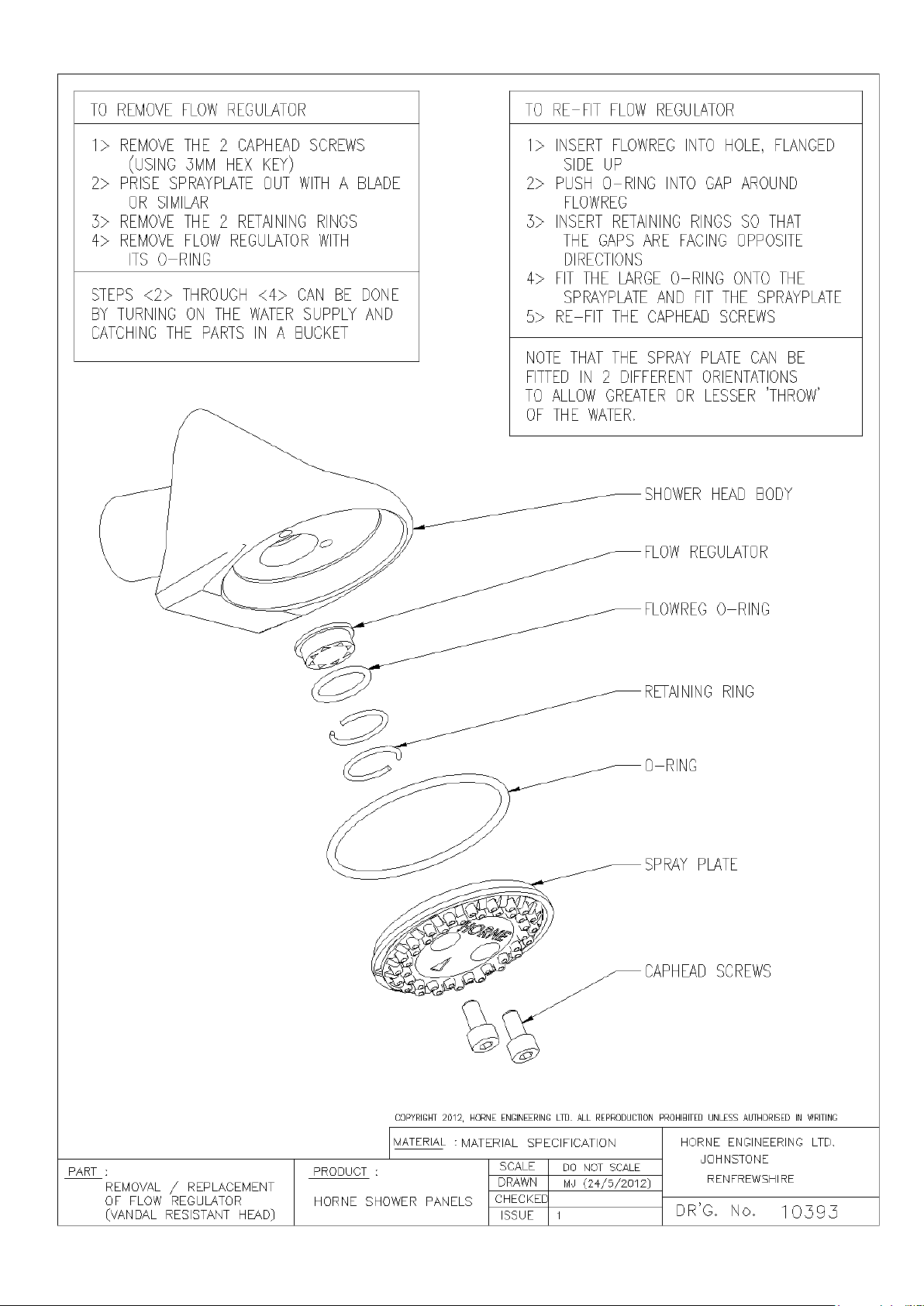
conserve water and energy. The drawing at the end of this document provides information for accessing the
flow regulator for removal or replacement.
Every HORNE TSV1-3 is supplied with an integral WRAS approved single check valve and integral large
surface area strainer. The Shower Panel terminates in 15mm copper pipes for hot and cold supplies. The hot
pipe is on the left, cold on the right, when viewed from the user’s perspective.
Issue 4 June 2016 1
Page 2
Horne Engineering Ltd
1) Position the Pre-plumbed Panel
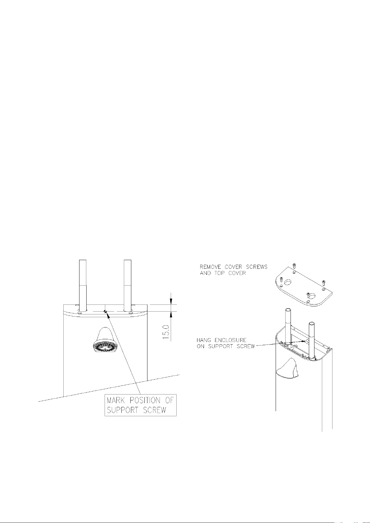
Identify a suitable position for the panel and mark a line on the wall level with the top of the casing.
Mark a point on the wall that is on the required centreline for the casing, 15mm below the line of the
top of the casing, for the support screw (see Fig. 1).
2) Install the Support Screw
Drill a 7.0mm dia hole in the wall and insert a wallplug and screw, leaving the head of the screw 1113mm from the wall surface. Note that a stainless steel screw (corrosion resistant) is supplied for this.
3) Hang the Panel on the Support Screw
Release the top cover of the panel by removing the four T-15 screws. Hang the panel on the support
screw by the larger hole in the middle of the back strap and let this take the weight of the enclosure
(see Fig 2).
Fig 1
Fig 2.
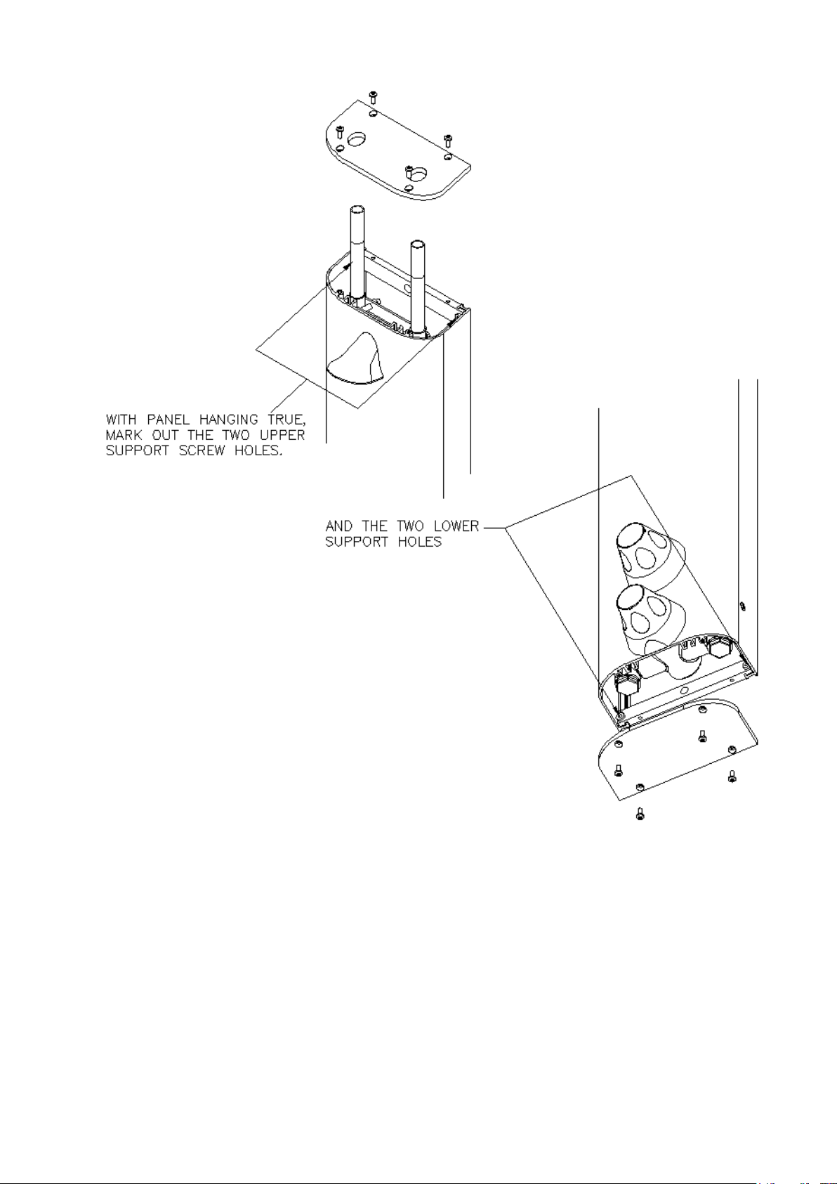
4) Mark out the 4 Support Holes
Ensure that the panel is hanging true and then mark out the holes for the 2 upper support screws.
Remove the bottom cover of the panel and mark out the 2 lower support screws (see Fig 3).
HORNE TSV1-3 Thermostatic Shower Panel
Installation Instructions (Surface Mounted with Auto Diverter valve)
General
The surface-mounted panel is supplied with a fitting kit containing the necessary fixings to attach it to the wall,
and with hex keys to assist with routine maintenance.
Installation
Installation of the pre-plumbed panel is particularly simple and involves mounting the panel on the wall,
connecting and flushing the water supplies.
Issue 4 June 2016 2
Page 3
Horne Engineering Ltd
Fig 3
5) Drill Support Holes
Carefully remove the panel from the temporary support screw and, being careful not to scratch the
panel or its covers, lay it down where it will not be damaged. Drill 4 x 7.0mm holes and install the wall
plugs.
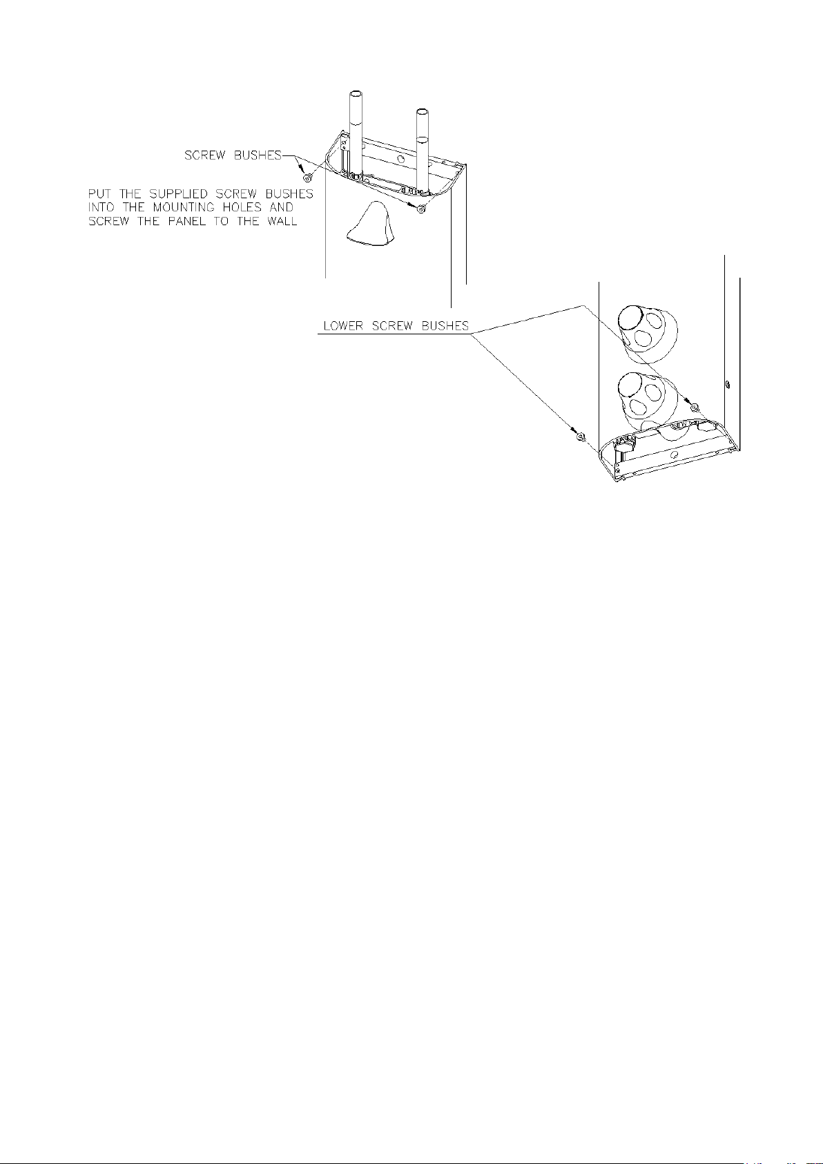
6) Attach the Panel to the Wall
Carefully re-hang the panel on the temporary screw and then attach it firmly to the wall by the four
other screws. Put the four supplied screw bushes in the mounting holes in the panel and then attach
the panel firmly to the wall by the four supplied stainless steel cross-head screws (see Fig 4). A bead
of silicon mastic can be used, if required, to cover any gaps behind the panel on uneven walls. Do not
mastic the lower end cap to the wall as this must be removed for maintenance.
Issue 4 June 2016 3
Page 4
Horne Engineering Ltd
Fig 4.
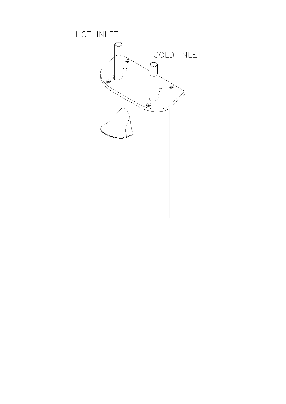
7) Connect the Supply Pipes
N.B. Ensure that the top cover of the panel is replaced prior to connecting up the supply pipes.
Connect the hot water supply to the left hand inlet, and cold water to the right-hand inlet (see Fig 5).
DO NOT OPEN THE WATER SUPPLIES AT THIS STAGE AS THEY HAVE NOT BEEN FLUSHED
OUT TO REMOVE THE DEBRIS IN THE PIPEWORK. SUCH DEBRIS CAN DAMAGE THE TSV1-3
VALVE.
Issue 4 June 2016 4
Page 5
Horne Engineering Ltd
Fig 5
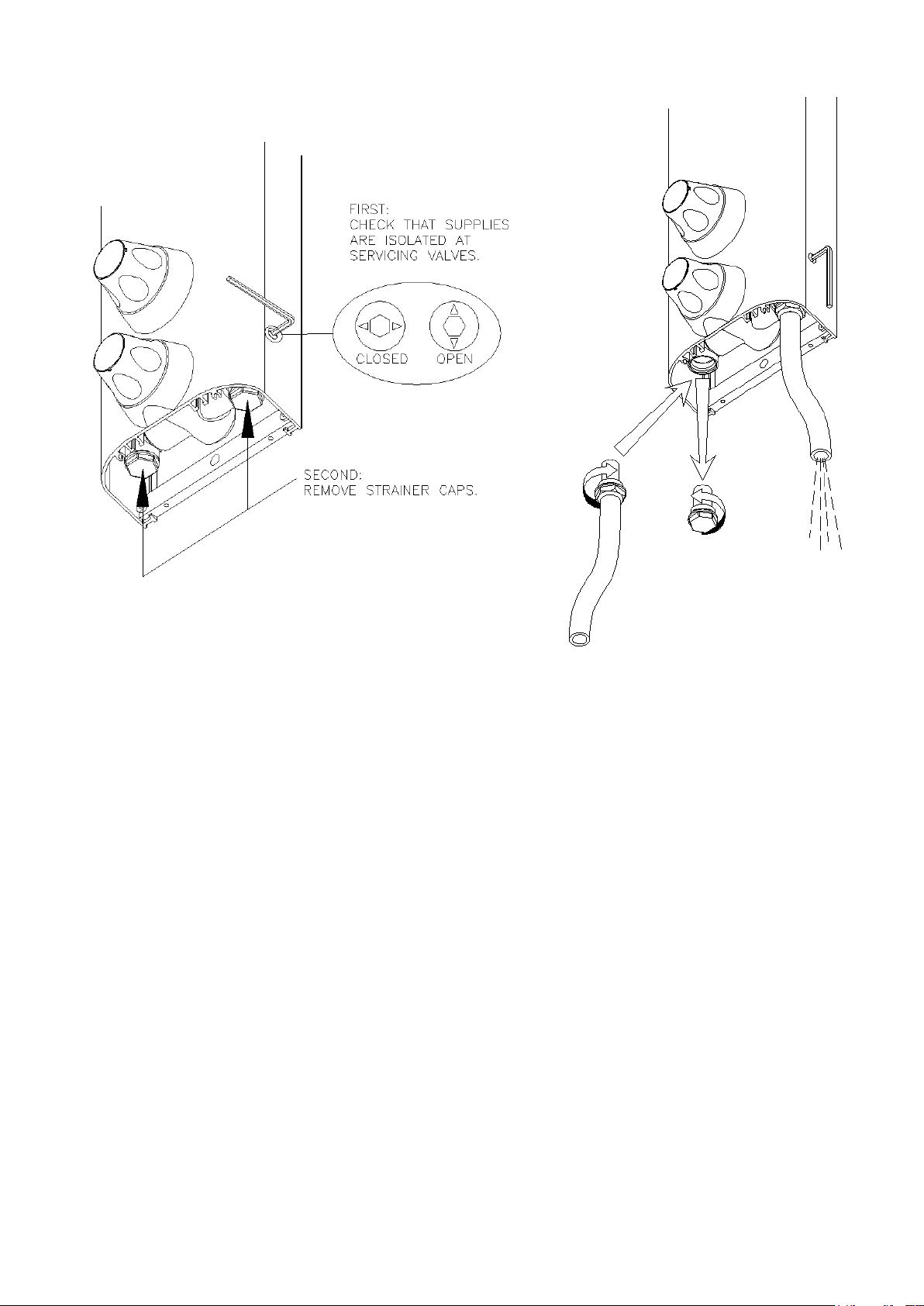
8) Flush the Pipework
Flush out the pipework in accordance with Water Bylaws 2000 (Scotland) and BS 6700:1997 (England
& Wales). The use of a Horne flushing kit is strongly recommended, because this connects directly to
the water inlets on the mixing valve. Access to the flushing points is gained from underneath the
casing through the lower end cap. Using the supplied 4mm hex key, isolate the cold and hot water
supplies at the low level servicing valves. Remove the strainer cap and strainer basket and screw in
the flushing adapter. Place the end of the flushing hose in an appropriate drain or container and turn
on the supply to flush as required. Remove the flushing adapter and replace the strainer cap. Repeat
for both hot and cold supplies. See Figs 6 & 7.
NOTE THAT IF THERE IS ANY DANGER OF FREEZING THEN THE PIPES AND TSV1-3 MUST BE
DRAINED TO AVOID DAMAGE.
Issue 4 June 2016 5
Page 6
Horne Engineering Ltd
Fig. 6
Fig. 7
9) Test for Leaks in Pipework
Ensure that the TSV1-3 on/off control is closed (i.e. turned fully clockwise) and open the supplies.
Open the low level servicing valves on the TSV1 casing (Fig. 6). Adjust the temperature control and
check for any water leaks upstream of the TSV1-3 valve. Make good any leaks found. The valve is
now ready for commissioning.
Note that if the controls, enclosure and shower accessories require cleaning then care must be taken
not the scratch them in the process. Wash off any surface dust with the shower spray before cleaning
with soapy water.
DO NOT USE ANY ABRASIVE CLEANERS OR SOLVENTS OR THE SURFACES MAY BE DAMAGED.
Issue 4 June 2016 6
Page 7

Horne Engineering Ltd
Supplementary Installation Instructions for ‘B’ Variants.
TSV1 Panel Mounted Shower Valves are available in versions with flexible braided stainless steel inlet hoses
rather than top entry isolating valves. These versions have Product Reference codes with the suffix B, e.g.
T605BLR.
The main difference, from an installation point of view, is that the water supplies may have to be connected
before the pre-plumbed enclosure is attached to the wall.
Accordingly, point 7 on the attached installation instructions (Connect the Supply Pipes) should be performed
before point 6 (Attach the Pre-Plumbed Enclosure to the Wall) unless alternative access is available to the
connections, e.g. via an access panel.
Note that the end of the braided hose inlets are colour coded with BLUE for the Cold Water Supply and RED for
the Hot Water Supply.
Care should be taken to ensure that the weight of the pre-plumbed enclosure is taken by the mounting screws
and NOT by the hoses.
Issue 4 June 2016 7
Page 8
Horne Engineering Ltd
COMMISSIONING
Ensure that the pipework has been flushed out before commissioning the TSV1-3
(see installation instructions).
Ensure that both hot and cold water supplies are open and at, or near to, their design temperatures and
pressures and that they are within the requirements of the valve as outlined on page 1. The NHS designation of
the valve should match the intended application.
Set the temperature control to the maximum temperature setting (i.e. rotate the control anticlockwise until it
stops).
Remove the handset, if fitted. Fully open the on/off control by turning it anticlockwise. It is important that the
valve is commissioned using the fixed sprayhead. A burst polythene bag over the sprayhead will help to catch
and deflect the spray during commissioning.
Allow the shower to run at maximum temperature setting until the water temperature has stabilised. Should the
temperature rise in an uncontrolled fashion, then the hot and cold supplies are probably reversed. Correct this
before proceeding.
The TSV1-3 is set in the factory to provide a maximum outlet temperature of approximately 41°C, but this
should be checked on site to ensure that the setting has not been altered and to ensure user safety.
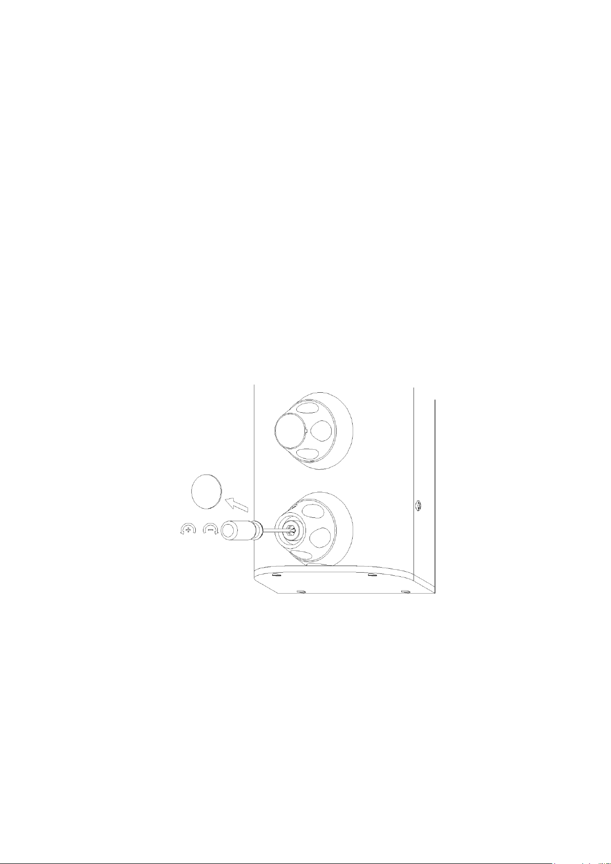
If the maximum temperature requires adjustment, remove the temperature control cap using a sharp blade or
the tip of a penknife and adjust the small slotted screw in the centre of the spindle. Adjust the screw
anticlockwise to increase the temperature, clockwise to decrease the temperature (see Fig. 8).
Fig 8.
After setting the maximum temperature, turn the shower on and off a few times and check that the maximum
setting is correct. Record the commissioning information on the attached maintenance sheet to permit the inservice performance of the valve to be assessed.
The automatic diverter valve switches flow between the fixed head and the handset. When the handset is
attached the flow is automatically diverted to it. Removing the handset automatically reverts flow to the fixed
head.
Finally, check the thermal shut-off facility of the TSV1-3 by performing a thermal shut off test. While the shower
is running, shut off the cold water supply. The flow from the showerhead should immediately stop or reduce to
a trickle, in which case the mixed water temperature rise should be less than 3°C. In either case, there is no
scalding risk. If the temperature rises above this then it is likely that there is contamination in the TSV1-3 that is
preventing it from shutting off the hot supply. Refer to the maintenance section of this booklet or phone the
factory for advice.
Issue 4 June 2016 8
Page 9

Horne Engineering Ltd
MAINTENANCE
Maintenance of the TSV1-3 shower valve is essential to ensure the product continues to perform to
specification after installation, and continues to afford scald protection. Record all maintenance carried out on
the attached commissioning and maintenance record.
When cleaning the external panel and knobs, never use cleaners containing abrasives or solvents as they may
damage the chrome plating. Use only a soft cloth and soap.
The frequency of routine maintenance of the TSV1-3 internals (i.e. cleaning, descaling etc) depends largely on
the condition of the water supplies, and local knowledge will dictate suitable intervals. In addition to this the
following precautions should be observed.
Initially check the strainer baskets for debris every three months and clean if required. This period can be
increased if appropriate once the general condition and cleanliness of the water is established.
Perform a thermal shut-off test every three months, and check the maximum temperature setting. See the last
paragraph in the Commissioning Instructions for details of the thermal shut-off test and re-adjustment of the
maximum temperature setting, if required.
If the maximum water temperature rises by more than 3°C from the commissioned setting then ensure that the
strainers are clean and that the isolating valves are fully open. Test the non-return valves as described below.
If these tests do not highlight the reason for the temperature rise then follow the procedure below for
investigating failure of the thermal shut-off test.
If the TSV1-3 fails the thermal shut-off test then remove the temperature control knob and the thermostatic
cover (see installation instructions for details) and check the internal surfaces for scaling. If the TSV1-3 body
requires descaling then it should be removed from the casing to do this. All rubber parts must be removed prior
to descaling. Do not forget the slide valve seal located inside the TSV1-3 body, which should always be
replaced with a new seal after removal. Maintenance kits, which contain “O” rings and/or the thermostatic
element, are available. Smear all “O” rings with silicon grease/oil prior to installing them. Torque the TSV1-3
cover to 13 Nm (10 lbft). This is to prevent the user from inadvertently unscrewing the cover during temperature
adjustment. Do not over tighten the cover.
Replace the “O” rings every three years (A Maintenance kit with spare “O” rings is available). Smear silicon oil
on all “O” rings prior to installation. Lightly smear the outside diameter of the slide valve with silicon oil prior to
installation.
Replace the thermostatic element and slide valve assembly at least once every 6 years in all TSV1-3 valves, or
more often if problems are experienced or in installations where the water is aggressive.
The on/off mechanism uses a ½ “ washer, which should be replaced when it leaks. Remove the cosmetic trim
and unscrew the on/off assembly. The washer is retained by a small nut. Do not over tighten this nut. Ensure
the on/off assembly is torqued down to 13 Nm (10 lbft) to prevent the user from inadvertently unscrewing the
assembly during flow control. Do not over tighten the assembly.
The automatic diverting valve diverts water to the handset whenever the handset is attached. Flow to the
handset is stopped by a check valve when the handset is removed.
The check valves prevent cross flow between hot and cold water supplies under unequal pressure conditions,
and are designed for long life with no maintenance. Their function can be tested as follows:
To test the check valves on the hot side, shut off the hot supply and ensure the cold supply is open. Be
prepared for leakage of trapped water from the pipe and remove the strainer basket on the hot side. Any
continuing leakage evident from the strainer body is likely to be coming through the hot supply check valves
(N.B. Ensure the hot isolating valve shuts off tight or it may cause leakage here).
To test the check valves on the cold side, shut off the cold supply and ensure the hot supply is open. Be
prepared for leakage of trapped water from the pipe and remove the strainer basket on the cold side. Any
continuing leakage evident from the strainer body is likely to be coming through the cold supply check valves
(N.B. Ensure cold isolating valve shuts off tight or it may cause leakage here).
Issue 4 June 2016 9
Page 10
Horne Engineering Ltd
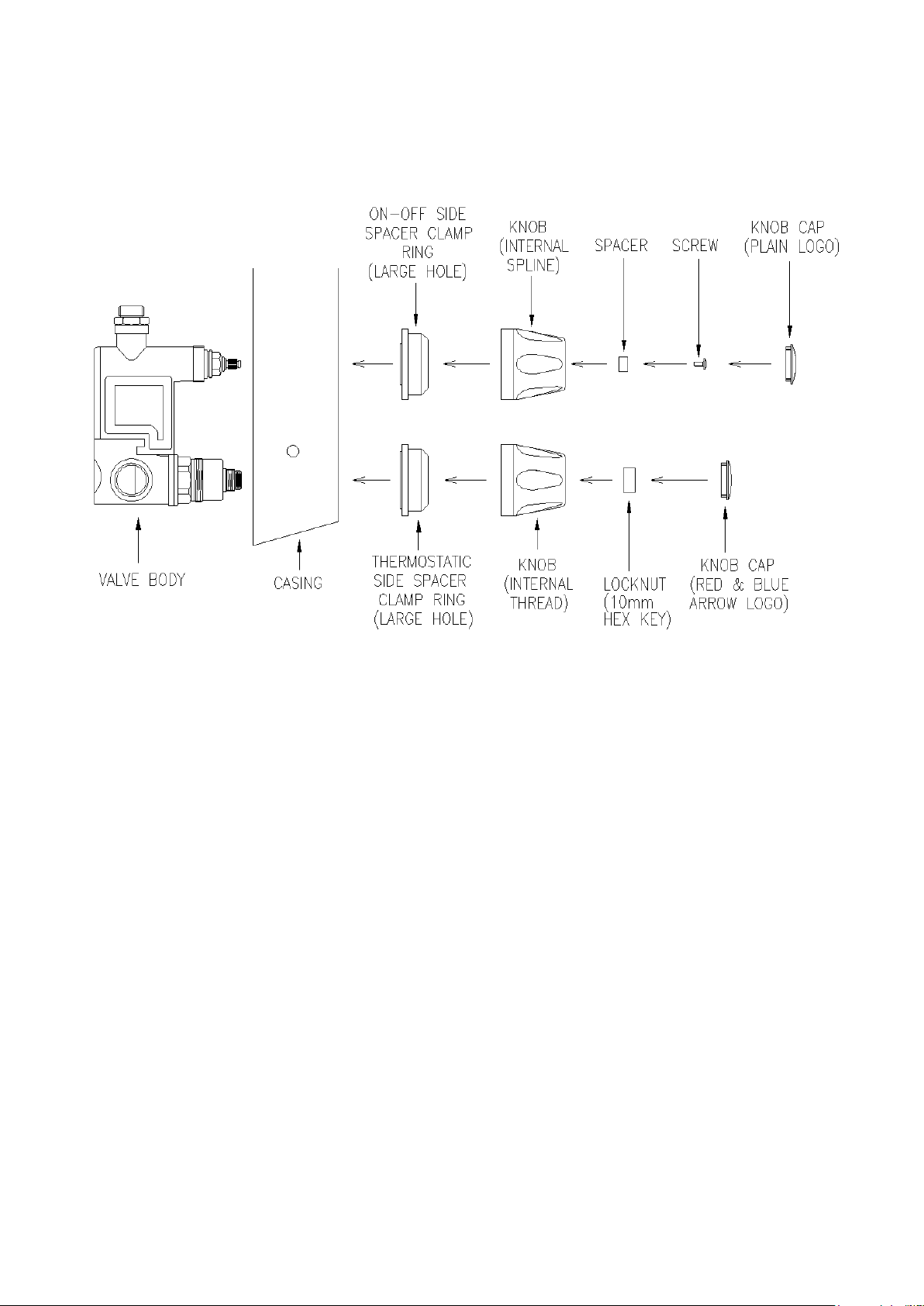
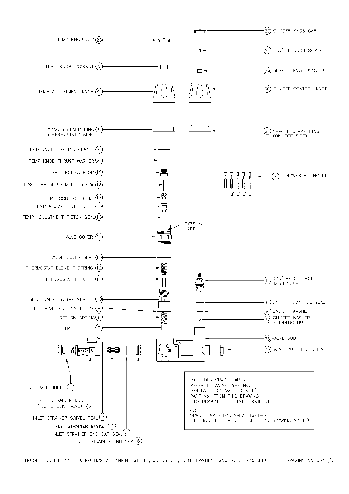
If either check valves is leaking then the inlet elbow (complete with check valves and strainer basket) should be
replaced. It is not possible to satisfactorily remove the check valves itself from the inlet elbow and should not
be attempted. The shower valve body must be removed from the pre-plumbed enclosure in order to remove the
inlet elbows. See Fig. 9 for the location of the parts.
Fig 9.
.
Issue 4 June 2016 10
Page 11

Horne Engineering Ltd
IN-SERVICE TESTING
Periodic testing should be carried out to check whether or not any deterioration has occurred in the
performance of the TSV1-3.
A thermal shut-off test, as described under maintenance, above, should be carried out. If the mixed water
coming from the showerhead is at a temperature of more than 3°C above the maximum mixed water
temperature setting then the TSV1-3 is due for maintenance.
Note: A thermostatic mixing valve in need of maintenance can be undetectable in normal use and only
become apparent when disruption occurs in the hot or cold water supply temperatures or pressures.
The frequency of in-service testing depends upon the condition of the water passing through the TSV1-3. Inservice testing must be carried out more frequently in hard water areas than in soft water areas. As a general
guide, in-service testing should be carried out at intervals somewhere between six months and 12 months. Inservice testing should be carried out at least every 12 months and, where the water is hard, the interval may be
less than 6 months. Experience of local conditions and the in-service testing record will dictate the frequency of
in-service testing.
Issue 4 June 2016 11
Page 12
Horne Engineering Ltd
Insert DRAWING 10393 showing position of Flow Reg.
Issue 4 June 2016 12
Page 13
Horne Engineering Ltd
Issue 4 June 2016 13
Page 14

Horne Engineering Ltd
Establishment:
Type of Valve: Horne TSV1-3 Shower Valve
Date Installed:
Installed by:
Location of Valve:
Commissioning Details Note: Fill in ALL information during commissioning.
Hot Water Supply :
HW Temp C
HW Pressure
Bar
Temp:
Instrumentation:
Pressure:
Cold Water Supply:
CW Temp C
CW Pressure
Bar
Mixed Temp at max draw-off:
Mixed Temp: C
Flowrate at max draw-off: l/min
Mixed Temp at low draw-off:
Mixed Temp: C
Flowrate at low draw-off: l/min
Instrumentation Used:
Temp:
Press:
Flow:
Cold Water Isolation Test
Max Mixed Water Temp during CW Isolation test: C Mixed Water Temp on restoration of CW Supply: C
Note: MWT should return within 2 degrees of set temp, and be no greater than 43C after this test.
Comments:
In-Service Testing Record
Date:
Hot Water Supply :
HW Temp C
HW Pressure
Bar
Temp:
Instrumentation:
Pressure:
Cold Water Supply:
CW Temp C
CW Pressure
Bar
Mixed Temp at max draw-off:
Mixed Temp: C
Flowrate at max draw-off: l/min
Mixed Temp at low draw-off:
Mixed Temp: C
Flowrate at low draw-off: l/min
Instrumentation Used:
Temp:
Press:
Flow:
Cold Water Isolation Test
Max Mixed Water Temp during CW Isolation test: C Mixed Water Temp on restoration of CW Supply: C
Note: MWT should return within 2 degrees of set temp, and be no greater than 43C after this test.
Comments:
Recommended Date of Next In-Service Test:
COMMISSIONING, MAINTENANCE & IN-SERVICE TESTING RECORD
Issue 4 June 2016 14
Page 15

Horne Engineering Ltd
In-Service Testing Record Establishment: Location of Valve:
Date: Type of Valve : TSV1-3 Shower Valve
Hot Water Supply :
HW Temp C
HW Pressure
Bar
Temp:
Instrumentation:
Pressure:
Cold Water Supply:
CW Temp C
CW Pressure
Bar
Mixed Temp at max draw-off:
Mixed Temp: C
Flowrate at max draw-off: l/min
Mixed Temp at low draw-off:
Mixed Temp: C
Flowrate at low draw-off: l/min
Instrumentation Used:
Temp:
Press:
Flow:
Cold Water Isolation Test
Max Mixed Water Temp during CW Isolation test: C Mixed Water Temp on restoration of CW Supply: C
Note: MWT should return within 2 degrees of set temp, and be no greater than 43C after this test.
Comments:
Recommended Date of Next In-Service Test:
In-Service Testing Record Establishment: Location of Valve:
Date: Type of Valve : TSV1-3 Shower Valve
Hot Water Supply :
HW Temp C
HW Pressure
Bar
Temp:
Instrumentation:
Pressure:
Cold Water Supply:
CW Temp C
CW Pressure
Bar
Mixed Temp at max draw-off:
Mixed Temp: C
Flowrate at max draw-off: l/min
Mixed Temp at low draw-off:
Mixed Temp: C
Flowrate at low draw-off: l/min
Instrumentation Used:
Temp:
Press:
Flow:
Cold Water Isolation Test
Max Mixed Water Temp during CW Isolation test: C Mixed Water Temp on restoration of CW Supply: C
Note: MWT should return within 2 degrees of set temp, and be no greater than 43C after this test.
Comments:
Recommended Date of Next In-Service Test:
IN-SERVICE TESTING RECORD
(Note: Photocopy this page)
Issue 4 June 2016 15
Page 16

Horne Engineering Ltd
Brochure Ref: L-180
Horne Engineering Ltd
PO Box 7
Rankine Street
Johnstone
SCOTLAND
PA5 8BD
Tel: +44 (0)1505 321455
Fax: +44(0)1505 336287
Email: [email protected]
www.horne.co.uk
Issue 4 June 2016 16
 Loading...