

Page 1

Horne Engineering Ltd
Horne Engineering Ltd
PO Box 7, Rankine Street
Johnstone, Renfrewshire
Scotland PA5 8BD
Tel 01505 321 455
Fax 01505 336 287
HORNE
Email [email protected]
Web www.horne.co.uk
HORNE 25 THERMOSTATIC MIXING VALVE
Type H-2501
Installation, Commissioning, Operating & Maintenance Instructions
1 Installing the Horne 25 TMV
1.1 Install the Horne 25 TMV as close as possible to the outlet to comply with HTM
2027 and HTM 2040. The dead leg from the Horne 25 TMV to the outlet should
not exceed 2 metres.
1.2 The Hot & Cold water supplies should be from a common source, i.e. the static
pressures should be equal.
1.3 Isolating valves must be fitted to the hot & cold water supply pipes.
1.4 The Horne 25 TMV can be fitted in any attitude with the mixed water outlet
pointing upwards, downwards, horizontally or at any angle between these planes.
2 FLUSHING OF PIPEWORK TO WATER SUPPLY BYLAWS (SCOTLAND) 2003
AND THE WATER SUPPLY (WATER FITTINGS) REGULATIONS 1999.
2.1 The most common cause for complaint regarding the performance of a valve is
traced to dirt or debris in the TMV or check valves.
2.2 Before a Horne 25 is commissioned, the hot and cold water pipework should be
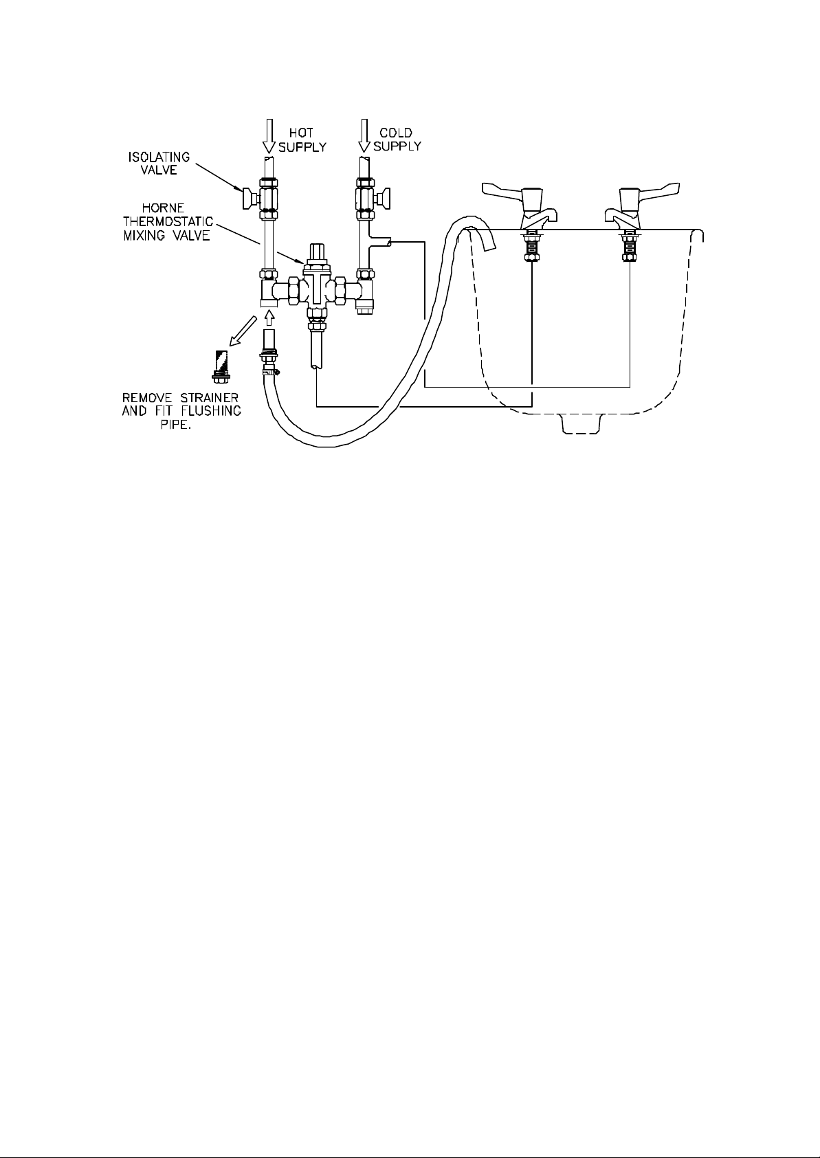
thoroughly flushed using the FLUSHING KIT shown in the diagram overleaf. The
FLUSHING KIT comprises a screwed adapter to fit the strainer body and a plastic
pipe to enable water to be flushed to drain. The kit may be ordered separately.
2.3 DO NOT FLUSH THE PIPEWORK BY REMOVING THE STRAINER
BASKETS AND OPENING THE TAPS.
2.4 DO NOT OPEN the hot water tap before flushing the hot and cold water pipework.
Issue 3 8/05 1
Page 2
Horne Engineering Ltd
2.5 The flushing procedure is as follows :-
2.6 During this procedure, keep the hot and cold water taps closed.
2.7 Close the hot and cold water ISOLATING VALVES.
2.8 Unscrew the END CAP (16) and remove the STRAINER BASKET (14) from the
strainer at the hot inlet.
2.9 Screw the FLUSHING KIT into the STRAINER BODY (13).
2.10 Place the outlet of the flushing pipe where it can drain freely. If draining into a
wash basin or bath, make sure that the plug is NOT in place and that water passing
through the flushing pipe is free to drain.
2.11 Open the hot water ISOLATING VALVE and allow any air in the pipework to
escape until water begins to flow to drain. Allow water to flow to drain until it is
perfectly clean and free from any dirt or debris.
2.12 Close the hot water ISOLATING VALVE.
2.13 Remove the FLUSHING KIT and replace the STRAINER BASKET (14) and END
CAP (16).
2.14 Repeat for the cold water inlet.
2.15 Re-open both ISOLATING VALVES.
2.16 The flushing procedure has now been completed.
Issue 3 8/05 2
Page 3

Horne Engineering Ltd
3 COMMISSIONING A NEW HORNE 25 TMV
3.1 Open the hot water tap and allow water to run through the Horne 25 TMV.
3.2 Check that the hot and cold water supplies are at or near their designated
temperatures and pressures.
3.3 Measure the temperature at the hot water tap. This is the temperature of the mixed
water.
3.4 If necessary, make minor adjustments to the temperature setting as described in
Section 4 below.
3.5 CARRY OUT A COLD WATER FAILURE TEST AS BELOW
3.5.1 Close the cold water isolating valve and simultaneously measure the mixed water
temperature. The flow of mixed water should immediately stop and then a drip or
trickle may be seen. The temperature of any water coming from the tap should not
be more than 2C above the mixed water temperature measured in 3.3 above.
3.5.2 If the Horne 25 TMV performs satisfactorily, close the hot water tap and open the
cold water isolating valve.
3.5.3 If the water coming from the tap is at a temperature of more than 2C above the
mixed water temperature setting, then the Horne 25 TMV is not cutting off the hot
water supply properly. The most likely cause for this to happen is dirt inside the
TMV. It should be dismantled and thoroughly cleaned and the pipework flushed
again. See 2.5 - 2.16.
3.6 The Horne 25 TMV is supplied with WFBS listed integral single check valves
located in each of the inlet couplings. To ensure the check valves are working
properly, proceed as follows :-
3.6.1 Start with both hot and cold taps closed and both hot and cold water isolating
valves open.
3.6.2 Close the cold water supply isolating valve.
3.6.3 Remove the cold water inlet STRAINER CAP (16) at the inlet to the Horne 25
TMV. After initial draining of water, there should be no flow whatsoever. This
indicates that the check valve at the cold water inlet is giving a tight shut-off.
3.6.4 Replace the cold water inlet STRAINER CAP (16) and open the cold water
isolating valve.
3.6.5 Close the hot water supply isolating valve.
Issue 3 8/05 3
Page 4

Horne Engineering Ltd
3.6.6 Remove the hot water inlet STRAINER CAP (16) at the inlet to the Horne 25
TMV. After initial draining of water, there should be no flow whatsoever. This
indicates that the check valve at the hot water inlet is giving a tight shut-off.
3.6.7 Replace the hot water inlet STRAINER CAP (16) and open the hot water isolating
valve.
3.7 The HORNE 25 TMV has now been commissioned.
4 TEMPERATURE ADJUSTMENT
4.1 The Horne 25 TMV is set at the factory to control the mixed water temperature at
approximately 42C.
The range of temperature adjustment is approximately 25C - 50C. To alter the
4.2
temperature setting, carry out the following procedure :-
4.3 Check that the cold and hot water supplies are at or near to their designated
temperatures and pressure.
4.4 Open the mixed water outlet and allow water to flow until the mixed water
temperature has stabilised. Make sure that the dead leg from the HWS to the
HORNE 25 TMV and from the HORNE 25 TMV to the outlet has fully cleared.
4.5 Use the ADJUSTING KEY (1), turn the ADJUSTING SCREW (2) clockwise to
reduce the mixed water temperature or anti-clockwise to increase it. Adjustments of
not more that half a turn at a time should be made. The temperature at the outlet
should be measured and allowed to stabilise before any further adjustments are
made.
4.6 After making an adjustment, close the hot water supply isolating valve for 10
seconds then reopen it and measure the mixed water temperature again. If a further
adjustment is required, repeat the procedure.
5 IN-SERVICE TESTING
5.1 Periodic testing should be carried out to check whether any deterioration has
occurred in the performance of the HORNE 25 TMV.
5.2 A COLD WATER FAILURE TEST should be carried out as described in 3.5.1
above. If the water coming from the tap is at a temperature of more than 2C above
the mixed water temperature setting then the HORNE 25 TMV is due for
maintenance.
NOTE: A Thermostatic Mixing Valve in need of maintenance can be undetectable
in normal use and only become apparent when a disruption occurs in the hot or cold
water supply pressures or temperatures.
Issue 3 8/05 4
Page 5

Horne Engineering Ltd
5.3 The frequency of in-service testing depends upon the condition of water passing
through the TMV. In-service testing must be carried out more frequently in hard
water areas than in soft water areas. As a general guide, in-service testing should be
carried out at intervals somewhere between 6 months and 12 months. In-service
testing should be carried out at least every 12 months and, where the water is hard,
the interval may be less than 6 months. Experience of local conditions and the inservice testing record will dictate the frequency of in-service testing.
6 MAINTENANCE
6.1 Maintenance of all Thermostatic Mixing Valves is essential. If a TMV does not
operate properly, there is a risk of someone being scalded. The frequency of
maintenance depends upon the condition of the water. The remarks in 5.3 regarding
in-service testing apply equally to maintenance.
6.2 "O" ring seals should be replaced at least every 3 years.
6.3 The THERMOSTAT ELEMENT (6) should be replaced at least every 6 years. All
other parts should be replaced only if physical damage has occurred.
6.4 MAINTENANCE PROCEDURES
6.4.1 Close hot and cold water inlet isolating valves and open pipework to allow
pipework to drain.
6.4.2 CLEANING STRAINERS - Unscrew END CAPS (16) and withdraw STRAINER
BASKETS (14). Clean the baskets and descale them, if necessary.
THERMOSTATIC MIXING VALVE MECHANISM. Minor maintenance can be
carried out with the HORNE 25 in situ :-
6.4.3 Unscrew VALVE COVER (3). Remove THERMOSTAT ELEMENT ASSEMBLY
(6), SLIDE VALVE ASSEMBLY (7) and RETURN SPRING (8).
6.4.4 The SLIDE VALVE ASSEMBLY (7) is a precision part and must be handled wit h
care.
6.4.5 Remove the ADJUSTING SCREW (2) by turning it clockwise until the thread
disengages.
6.4.6 The SLIDE VALVE SEAL (9) can be removed by piercing the rubber with a sharp
pointed probe. Take care not to bruise the edges of the groove.
6.4.7 If the SLIDE VALVE SEAL (9) has been removed, then it MUST be replaced with
a new one. NEVER re-use an "O" ring.
Issue 3 8/05 5
Page 6

Horne Engineering Ltd
6.4.8 Thoroughly clean all components.
6.4.9 Flush out the valve body by replacing the VALVE COVER (3) and ADJUSTING
SCREW (2) and opening the isolating valves and allowing water at full bore to pass
through the body to the outlet.
6.4.10 If dirt is seen during flushing then carry out the FLUSHING PROCEDURE in
Section 2.
6.4.11 Re-assemble the HORNE 25 TMV (See 6.6).
6.5 MAJOR MAINTENANCE
6.5.1 For this remove the HORNE 25 TMV from the pipework.
6.5.2 Unscrew STRAINER COUPLING NUTS (11) and the OUTLET PIPE
COUPLING.
6.5.3 Lift the valve out of the pipework.
6.5.4 DO NOT grip the valve body in a vice. This could distort the body and jam the
internal parts.
6.5.5 Remove the VALVE COVER (3) and internal parts as referred to in 6.3.1 to 6.3.4.
6.5.6 If the valve body requires de-scaling, remove all "O" ring seals and use a
proprietary fluid for this purpose. Do not put the THERMOSTAT ELEMENT
ASSEMBLY (6) in the descaling fluid.
6.5.7 Inspect the condition of the HOT VALVE FACE and the COLD VALVE FACE. If
the valve faces show signs of deterioration they can be resurfaced as follows :-
6.5.8 Using a mandrel (Tool No. 7342) lap the HOT VALVE FACE using a water
soluble scouring paste. Use 800 grade wet abrasive paper on a flat surface to lap the
COLD VALVE FACE.
6.5.9 Reassemble the HORNE 25 TMV.
6.6 Re-Assembly
6.6.1 When fitting new "O" rings, it is advisable to smear them sparingly with a WFBS
listed silicon grease.
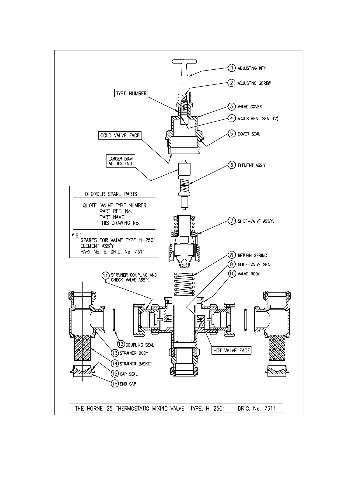
6.6.2 Insert the components into the HORNE 25 TMV in the order shown on Drawing
7311.
Issue 3 8/05 6
Page 7

Horne Engineering Ltd
6.6.3 Insert the ADJUSTING SCREW (2) into the VALVE COVER (3) and turn anticlockwise until the top of the ADJUSTING SCREW (2) is approximately 5mm
below the top of the lockshield.
6.6.4 When the internal components have been located loosely in the valve body, place
the VALVE COVER (3) over the THERMOSTAT ELEMENT ASSEMBLY (6)
and then push gently and turn until the thread on the VALVE COVER (3) engages
with the VALVE BODY (10). The internal components are self-aligning.
6.7 Check Valves
6.7.1 Check Valves are located within the STRAINER COUPLING (11). They are not
removable. They are designed for a long, maintenance-free life.
Issue 3 8/05 7
Page 8
Horne Engineering Ltd
Issue 3 8/05 8
Page 9
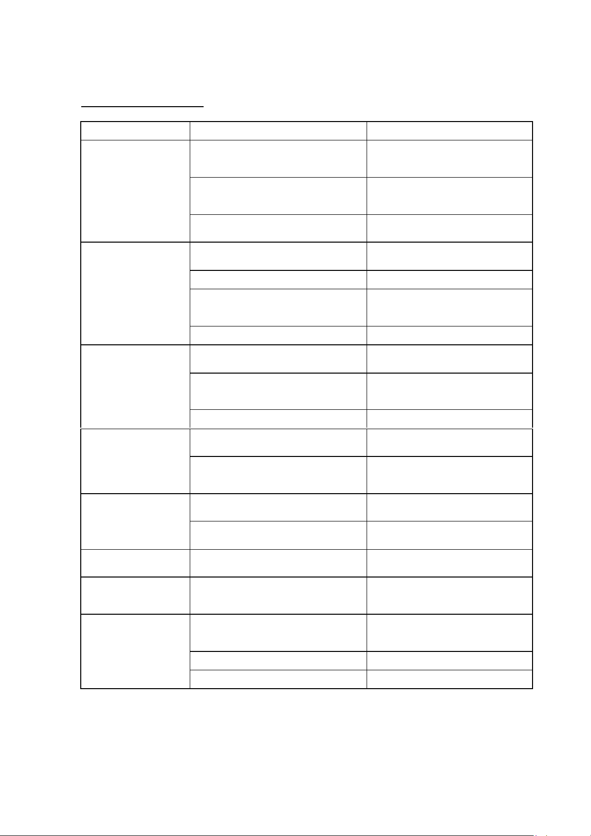
FAULT FINDING CHART
SYMPTOM POSSIBLE CAUSE ACTION
Horne Engineering Ltd
Mixed water temperature too
high
Mixed water temperature too
low
Mixed water flow rate too
low.
Temperature setting too high.
Temperature has been set when the hot water
temperature is too low
Hot water has migrated into cold water supply Inspect Check Valve at cold inlet
Thermostat Element has failed this can be checked
by carrying out a hot or cold water failure test.
Temperature Setting too low Re-adjust temperature setting
Hot water supply temperature has fallen Check hot water supply system
Cold water has migrated into hot supply Inspect Check Valve at hot inlet
Cold valve face requires cleaning Remove valve Cover (5) and service valve face
Partly blocked strainers Clean strainers
Unusually high pressure drop in supply pipework Check all valves are full open.
Extra Demand added to system Check pipe sizing
Re-adjust temperature setting
If the check valve leaks replace the strainer
body and check valve sub-assembly
Replace element (8)
If the check valve leaks replace the strainer
body and check valve sub-assembly.
Check Pressurisation unit
Check mains supply
Mixed water temp does not
respond to adjusting screw
Mixed water temp changes
and is not steady
Water at outlet runs full hot or
full cold
Valve continues to pass cold
water when hot supply is
isolated
Valve continues to
pass hot water when
cold supply is isolated
Slide-Valve (9) is seized Valve requires de-scaling
Hot and cold inlets reversed Remove HORNE 15 TMV from pipes and
Slide-Valve (9) is seized Valve required De-Scaling
Thermostat element has failed (This can be checked
by carrying out a hot or cold water failure test)
Hot and cold inlets are reversed Hot inlet is marked with Red dot
Cold valve face requires cleaning Remove valve cover (5) and service cold valve
Fouling at hot valve seat Clean hot valve face
Slide-Valve seal is damaged Replace Slide-Valve Seal (13)
Element has failed Replace Element (8)
reverse connections.
Connect inlet with red dot to hot pipe
Replace elements (8)
Cold inlet is marked with Blue dot
face
Issue 3 8/05 9
 Loading...