

Page 1
Outlaw Installation Manual
127CX & 228VX
WARNING: To ensure the longevity of your
system, reading and following these instruc-
tions are recommended. Make sure to change
lters and to drain the moisture from your
tank on a regular basis.
Page 2

HornBlasters
Outlaw Air Horn
Installation Guide
Before Getting Started
Read over the entire instruction guide before you begin your installation.
Support Line: +1 (813) 783-8058
Fax Line: +1 (813) 783-2407
[email protected]
www.hornblasters.com
Kit Contents:
• HornBlasters Outlaw AIr Horn
• Viair Air Source Kit (20003, 20005, 20007, 20008)
• 17’ 1/2” Airline
• 17’ 10 Gauge Wire
• 17’ 18 Gauge Wire
• 3 x 18-22 Gauge Butt Connector
• 3 x 10-12 Gauge Butt Connector
• 1 x Toggle Switch
• 2 x 18-22 Gauge Female Bullet Connector
• 2 x 18-22 Gauge Ring Terminal
• 1 x 10-22 Gauge Ring Terminal
• 1 x 10-22 Gauge Male Quick Disconnect
• 1 x 18-22 Gauge Male Quick Disconnect
• 1 x 10-12 Gauge Scotch Lock
• 1 x 18-22 Gauge Scotch Lock
• 1 x 35 Amp Fuse
• 1 x Inline Fuse Holder
IMPORTANT: This complete train horn kit uses 12 volt DC components. Only install this kit
with a 12 volt DC power source.
Important Safety Instructions
CAUTION: To prevent the risk of electrical shock or electrocution:
• Do not disassemble any electrical components of this horn kit (air compressor, air valve, pressure switch).
• Do not attempt repairs or modifications of any component. Please refer to qualified service agencies for all service and
repairs.
• Do not operate any component where it can fall or be submerged into water or any kind of liquid.
• Do not reach for any component that has fallen or been submerged into water or any kind of liquid.
• Use the included components with 12 volt DC systems only.
• Do not leave the air system unattended during use.
WARNING: To prevent injury:
• Never allow children to operate the compressor or air horn. Use close supervision when operating this equipment near
children.
• The air compressor will become very HOT during and immediately after operation. Do not touch any part of the compressor
with your bare hands during or immediately after use.
• Do not use this product near open flames or explosive materials or where aerosol products are being used.
• Do not operate this product where oxygen is being administered.
• Do not pump anything other than atmospheric air.
• Never use this product while sleepy or drowsy.
• Do not use any tools or attachments with the supplied air source unit without first determining maximum air pressure for
that tool or attachment.
• Never point any air nozzle or air sprayer toward another person or any part of your body.
• The included compressor is equipped with an automatic reset thermal protector and can automatically restart after the
thermal protector resets. Always cut off power source when thermal protector becomes activated.
• Use only in well ventilated areas.
• Do not sound the air horn(s) in close proximity to another person’s or your own ear(s).
• Do not fill the included air tank above 150 PSI. Doing so may result in death or serious injury.
1
Page 3

Safety During Installation
• Disconnect the ground of your battery before beginning your installation.
• Use eye protection when operating drills.
• Take your time and do not rush your installation.
Installing Your Train Horn Kit
Planning Your Installation
This is the most important step in your installation.
• Plan out the location of each component before starting your installation.
• Make sure you have enough airline and wire to install the system before beginning the installation.
• Make sure mounting locations are secure and void of debris.
• Try to keep the supply wire to the compressor as short as possible. Wires lose voltage over distance therefore shorter wires
will result in better performance.
• Mount your air source unit in a location that is as cool as possible and away from heat sources. This will make your
compressor run cooler and last longer.
• Your air source unit must be mounted upright with the compressor above the tank. Failure to mount the unit in this position
will allow any condensation buildup to drain back in to the compressor and harm its components, and also will disrupt the
compressor’s ability to cool.
• Teflon tape or a locking compound should be used on every fitting in your air system to prevent air leaks; unless a white or
red PTFE paste is already applied.
• Use the supplied 10 gauge wire or thicker (lower gauge #) wire to power your air compressor.
Recommended Tools
• 3/8” Long Socket (Horn Front Mount)
• 1/2” Long Socket (Horn Rear Mount)
• 1/2” Wrench
• 9/16” Wrench (1/4” NPT Fittings)
• 7/8” Wrench (1/2” Banjo)
• 10mm Wrench or Socket (Air Source Mounting)
• 12mm Wrench
• Drill (3/16” & 7/16” Bits)
• Wire Cutter/Stripper
• Tubing Cutter/Razor
• Eye Protection
I. Installing Your Hornblasters Train Horns
Locate an area for your horns that is dry and free from debris. The horns can be mounted in any direction and still be heard
from all around. The horns should not be mounted where they will be completely submerged or will receive any kind of
impact. Horns may be mounted directly to your vehicle, on a medium such as grommet strips (plumber’s strap), sheet metal
or any sort of custom bracket.
1. Locate a secure, dry, and safe position for your horns.
2. Make a mounting template by tracing the mounting bracket on the horn.
3. Using the mounting template drill 3/16” holes for the mounting bracket of the horn.
4. Secure the horn using the supplied mounting hardware.
II. Installing Your Air Source Kit
Locate a flat and secure installation area that will remain free of dust, dirt, and debris (your compressors performance is
directly affected by air quality). Try to keep the distance of the unit from the battery to a minimum to keep your compressor
running at maximum performance.
1. Disconnect the ground cable from the vehicle’s battery.
2. Position the unit in the desired location and secure it using the supplied mounting hardware (10mm).
3. Remove the orange plug in the compressor’s inlet and mount the included air filter in its place.
2
Page 4

III. Installing Your Air Tubing & Air Valve
Before cutting any air tubing make sure to double check your measurements. We recommend cutting lengths with at least an
extra inch per line just to be safe. Compression ttings use ferrules (olives) that should be used only once. When threading any
ttings make sure to use Teon tape to prevent air leaks.
IMPORTANT: The air horns and connecting ttings up to the outlet of the air valve will use 1/2” air line. The air source unit will
use 1/2” air line to connect to the inlet port of the air valve.
IMPORTANT: Do not make any kinks in your air line. Doing so will disrupt air ow and the damage is irreversible.
Fitting Flow Chart
[Air Source] » [1/2” Line] » [Air Valve]
1. Plan out the ttings placement out before you begin and make sure you understand the correct order.
2. Make sure that your tank is empty of air and that the compressor is not running during installation.
3. Install the air line carefully using two wrenches for each compression tting. Use one wrench to hold the body of the
tting stationary and another to tighten the compression nut.
4. Measure and plumb one length of 1/2” tubing from the tank compression tting to the air valve located on the horn.
5. Next connect your air valve’s inlet port to your air source unit using 1/2” air line and 1/2” to 1/2” compression tting.
IV. Wiring Your Valve & Air Source Unit
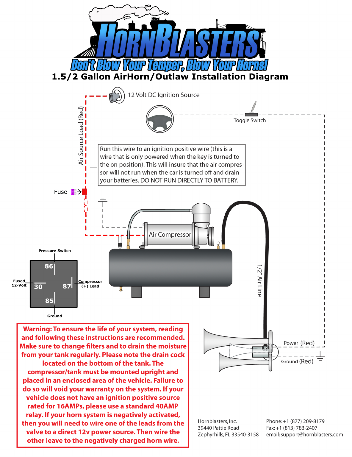
Your train horn kit will use two completely independent circuits. One circuit will connect your horn trigger (push-button
intermittent switch, or toggled factory button) to your electric valve. The other circuit will connect your accessory trigger
(ignition positive wire) to your air source kit.
Valve Wiring Flow Chart
[Factory Horn Wire] » [Toggle Switch] » [Air Valve] » [Ground]
Air Source Wiring Flow Chart
[Remote Wire/Accessory Wire] » [Inline Fuse] » [Air Source Unit] » [Ground]
Circuit 1
1. Begin by wiring your horn trigger.
a. If you are intending to use your factory horn switch, start by locating the load wire of the horn button
(positive when horn is depressed in a standard vehicle) and wiring it to the included toggle switch.
b. If you are going to use a push button switch (intermittent toggle switch) wire a fused (5A) wire from any 12
volt source desired (battery) to your switch.
2. Next wire your switch to any pole of your air valve using the female bullet connector.
3. Wire the other side of the air valve to ground using the female bullet connector.
4. Test your circuit by activating your trigger and listening for a ‘click’ from the valve.
Circuit 2
1. Locate an accessory line in your vehicle that is capable of a 16 amp load.
2. Wire your accessory line using an inline fuse (35A) to your air source unit (Red Wire).
3. Ground the other side of your air source unit (Black Wire) to ground.
4. Your air compressor system will not turn on automatically when power is on (Key is in ‘accessory’ or ‘on’ position) and
automatically turn itself o upon reaching destination.
You’re Done!
It’s time to test your horns! Share your install photos on our facebook at www.facebook.com/hornblasters or instagram/twitter
@hornblasters and don’t forget to check www.trainhornforums.com, the largest train horn community on the internet.
3
Page 5

Maintenance & Tips
Disconnect electrical components and drain you air system before performing maintenance.
General Air Horn System Maintenance
• Check your air horns for debris when appropriate and at least once a month and clean when necessary.
• Drain your air system at least every other week, to remove any condensation buildup on the inside of you air tank.
• Make sure you air compressor is clean and free from debris at all times.
• Periodically change your two stage air filter on your compressor.
Tips
• Make sure your engine is running when you air compressors are in use to insure proper voltage and to prevent damage to
your system.
• Do not run your compressor above its maximum rated working pressure. Doing so will not only void you warranty, but may
also damage your compressor.
• The air horns are pre-tuned to a locomotive chord and to their loudest possible tone. Do not adjust the tuning screw on the
horns. Doing so will void your warranty and may damage the horns if improperly adjusted.
Troubleshooting
Problem
Air horn will not sound.
Horn tone changes when
sounded
Excessive moisture in horn or
safety discharge.
Compressor will not run.
Thermal overload protector cuts
out repeatedly.
Excessive knocking or rattling
Tank pressure drops when
compressor shuts off
Compressor runs continuously
and air flow lower than normal
Compressor runs continuously
causing safety valve to open.
1. No pressure in air tank.
2. No power or toggle switch in ‘Off’ position.
3. Blown fuse.
4. Loose connections or bad ground in air valve
circuit (circuit 1).
1. A side fitting as used to connect the air source (line
from valve) to the 4-point banjo manifold.
2. Air line connecting the horns is not of equal length.
1. Excessive water in tank.
2. Compressor is exposed to high humidity.
1. No power or toggle switch in ‘Off’ position.
2. Blown fuse.
3. Motor overheat.
4. Faulty pressure switch.
1. Lack of proper ventilation/ambient temperature too
high.
2. Compressor valves failed.
1. Loose mounting bolts.
2. Worn bearing on eccentric or motor shaft.
3. Cylinder or piston ring is worn.
1. Loose drain cock.
2. Air valve or check valve is leaking.
3. Loose connections.
4. Defective safety valve.
1. Excessive air usage.
2. Loose connections.
3. Worn piston ring or inlet valve.
4. Clogged air filter element.
1. Faulty pressure switch.
2. Defective safety valve.
1. Check that air tank is pressurized.
2. Make sure all toggle switches are on.
3. Disconnect electrical components and
replace fuse.
4. Check that all electrical circuits are secure and not
corroded.
1. Check that air source (line coming from valve) is
entering the center fitting of the 4-point banjo manifold.
2. Check that the air line connecting each horn to the
4-point banjo manifold is of equal length.
1. Depressurize tank using safety, then drain tank. Tilt the
tank to drain moisture and drain more frequently.
2. Move the compressor to an area with less humidity.
1. Make sure all toggle switches are on.
2. Disconnect compressor from power & replace fuse (35A).
3. Let compressor cool off for about 30 minutes for thermal
overload switch to reset.
4. Replace pressure switch.
1. Move compressor to a well ventilated area or an area
with a lower ambient temperature.
2. Replace air compressor.
1. Tighten bolts.
2. Replace compressor.
3. Replace compressor.
1. Tighten drain cock.
2. Replace air valve or check valve.
3. Check all air connections with soap and water solution
and tighten as necessary.
4. Replace safety valve.
1. Decrease air usage.
2. Check all connections with soap and water solution
and tighten as necessary.
3. Replace compressor
4. Replace air filter element.
1. Replace pressure switch.
2. Replace safety valve.
Can’t Figure It Out?
No problem! Give us a call at 813-783-8058, or email at [email protected] and we’ll be more than happy to help you fix you system. Also feel free
to visit our online horn community, www.trainhornforums.com, for more information.
4
Page 6

Photograph & Media Submission Guidelines
Send in your installation photographs and any other media for a chance to be featured on our web site!
General Photograph Submission Guidelines
• Please submit clean, concise photographs. Make sure your subject is clearly visible and in focus.
• You may submit and digital image format either via email at [email protected], or via digital media (CD, DVD, etc).
• Make sure to include some kind of personal information with your submission. We would love to be able to contact you and
thank you.
Installation Gallery Submission Guidelines
• Please take at least one photo of each major components of your installation (horns, compressor, tank, valve, switches, etc).
• Don’t forget to send us some shots of your vehicle too! If we can't tell what the install is on, we probably won’t post it.
• Include as much installation information as possible.
¤ Who installed the system and when was it installed?
¤ How long did the install take?
¤ What is the year, model, and style of your vehicle?
¤ If you took your system to a shop, would you recommend the shop to others?
¤ Do you have any comments or tips about the installation?
¤ Anything else you want to tell us, we always appreciate your feedback!
• Optionally include a little personal information:
¤ Your name (if you would like your full name to be displayed, you have to let us know!)
General Video Submission Guidelines
• We accept all kinds of media. Please provide us with the highest quality media to prevent video degradation.
• We can read all formats of video. We recommend using either the default your camera records with; or if you are compressing
the video, we recommend using AVI containers and Xvid, Divx, or a MPEG codec. We recommend AGAINST using any kind of
Windows Media*, Real Media*, or Apple QuickTime* formats.
• You may submit any digital image format either via email at [email protected], or via digital media (CD, DVD, etc).
• Make sure to include some kind of personal information with your submission. We would love to be able to contact you and
thank you!
*Windows, Windows Media, Real, Real Media, Apple, and QuickTime are all registered trademarks and copyright of their
respective owners.
Get Involved In The Train Horn Community
No matter what your take is on your new train horn kit, it’s always good to have someone to share your stories with.
Trainhornforums.com is the largest train horn community online and provides a place to share photos of your ride, post
videos, catch up with other train horn and HornBlasters fans, meet other train horn enthusiasts, or even find help with a
complicated question.
Go online to www.trainhornforums.com and sign up today!
@hornblasters #hornblasters
/hornblasters
Make sure to follow us on all the popular social media! Facebook, Vine, Twitter, Youtube, and Instagram. Show o your
install and tag us in all your photos!
5
Page 7
Page 8

 Loading...