

Page 1
Custom-Grade™ Dies
Crimp/Seater Die
Crimp/Seater Die
Page 2
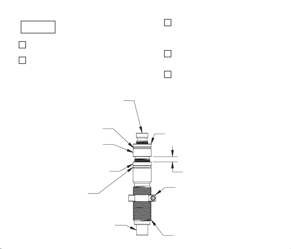
Depend ing on the calib er of die set /alignme nt
set up
1.
As wi th all dies, disassemble the Crimp/Seater
Die and clean thoroughly.
2.
Reassemble according to illustration, setting the
dist ance between the Crimp Adjust Screw and
the Crimp Adjust Lock Ring to approximately ¼
inch. When tightened properly, the Crimp Adjust
Lock Ring should have firm tension on t he O-ring
against the Seater Die Body.
sleeve yo u are using, the H ornady Crimp /Seater Di e
will ei ther "tape r" or "roll" cri mp your cases.
Seat Adjust Screw
(adjusts bullet seating depth)
3.
With a case in the shell holder, raise the press
ram to the top of its stroke. Screw the assembled
Crimp/ Seater Die into the press unt il resistance
is felt. This resist ance is the case star ting to
crimp in the Alignment Sleeve.
4.
Screw the Sure-Loc Lock Ring down against the
press or Lock-N-L oad® Bushing and lock into
place by tightening the cap screw on the ring.
5.
Loosen the Crimp Adjust Lock Ring while holding
the Crimp Adjust Screw and then back the Crimp
Adjus t Screw off approximately ½ turn. Retighten
the Crimp Adjust Lock Ring while holding the
Crimp Adjust Screw.
Rubber Flat Washer
Crimp Adjust Screw
(adjusts bullet seating depth)
Crimp Adjust Lock Ring
O-Ring
Alignment Sleeve
Seat Adjust Lock Ring
1/4"
Sure-Loc Lock Ring
Crimp/Seater Die
Page 3

6.
Now we will set the bullet seating depth. Loosen
the Seat Adjust Lock Ring and back the Seat
Adjus t Screw out several turns to assure that the
bullet won’t be seated too deep.
7.
Lower the press ram and set t he bullet on the
case. Raise the press ram, guiding the bullet /
case into the Crimp /Seater Die.
8.
While press ram is at the top of the s troke, thread
the Seat Adjust Screw into die until resistance is
felt. This resistance is the bullet start ing to seat
into the case.
9.
Set the bullet seat depth by lowering the press
ram, threading the Seat Adjust Screw into the die
and raising the press ram again until the desired
seating depth/car tridge length is obtained.
Note: Do not, at this t ime, t ighten the Seat Adjust
Lock Ring.
10.
Now we will set the crimp on the cartridge. Your
new Hornady® Crimp/ Seater die will achieve
this by adjusting the Crimp Adjust Screw as
opposed to loosening the Sure-Loc Lock Ring
and adjusting the entire body as with most seater
dies. Since the lock ring was set in step 4, it
doesn’t have to be moved.
11.
With the cartridge in the shell holder, raise the
press ram again to the top of its stroke.
12.
Loosen the Crimp Adjust Lock Ring several turns
while holding the Crimp Adjust Screw.
13.
Hold the Seat Adjus t Screw from turning and
thread the Crimp Adjust Screw into the die until
resistance is felt. This resistance is, again, the
case starting to crimp.
14.
Continue setting crimp by lowering press ram,
holding the Seat Adjust Screw, threading the
Crimp Adjus t Screw into the die in 1/8 turn
increments, and raising the press ram again
until the proper crimp is obtained. The 1/ 8 turn
recommendat ion is due to the fine adjustment
of the crimp. In the next step, a bullet will be
seated and crimped in one step and due to this,
an incorrect crimp or over excessive crimp will
resul t in bullet swaging or case bulging.
15.
Next, lower the press ram and remove the
cart ridge. Place the nex t set of component s
in the press and raise the ram to the top of the
stroke, guiding the case /bullet into the die. This
will seat the bullet as well as crimp it in the case.
16.
Fine tune the crimp/seat depth if necessary.
Remember when adjusting the Crimp Adjust
Screw, hold the Seat Adjust Screw and when
adjusting the Seat Adjust Screw, hold the Crimp
Adjus t Screw. Doing this will allow the crimp
amount to be adjusted without moving the
seating depth and vice versa.
17.
Once the crimp amount and the seat depth have
been obtained, the Crimp Adjust Lock Ring and
Seat Adjust lock ring will need to be tightened.
First, tighten the Crimp Adjust Lock Ring; you'll
need to hold the Crimp Adjus t Screw so it doesn't
move. T hen tighten the Seat Adjust L ock Ring
down firmly on the Rubber Flat Washer. Hold the
Seat Adjust Screw so it doesn't turn.
18.
Your die should now be set and will give you
years of reloading enjoyment.
Page 4

EXPLODED VIEW
4
3
1
10
ITEM NO. PART DESCRIPTION PART NO.
1 Die Bod y Seater T C/E XP 2.7 5 398900
2 Seat A djust Scre w 398907
3 Alignment Sleeve Varies w ith calib er
4 Seat ing Stem Varies wi th caliber
5 Crimp Adjust Screw 398905
6 Crim p Adjust L ock Ring 398906
7 O-Ring 480083
8 Washer Flat Rubber 398067
9 Ring L ock Seater Die 044800
10 Sure -Loc Lock R ing 044000
NOTE: When callin g for part s, please re ference par t number.
9
2
8
5
6
7
Page 5

P.O. Box 1848 • Grand Island, NE 68802-184 8
(308) 382-1390 • ww w.hornady.com
 Loading...