

Page 1
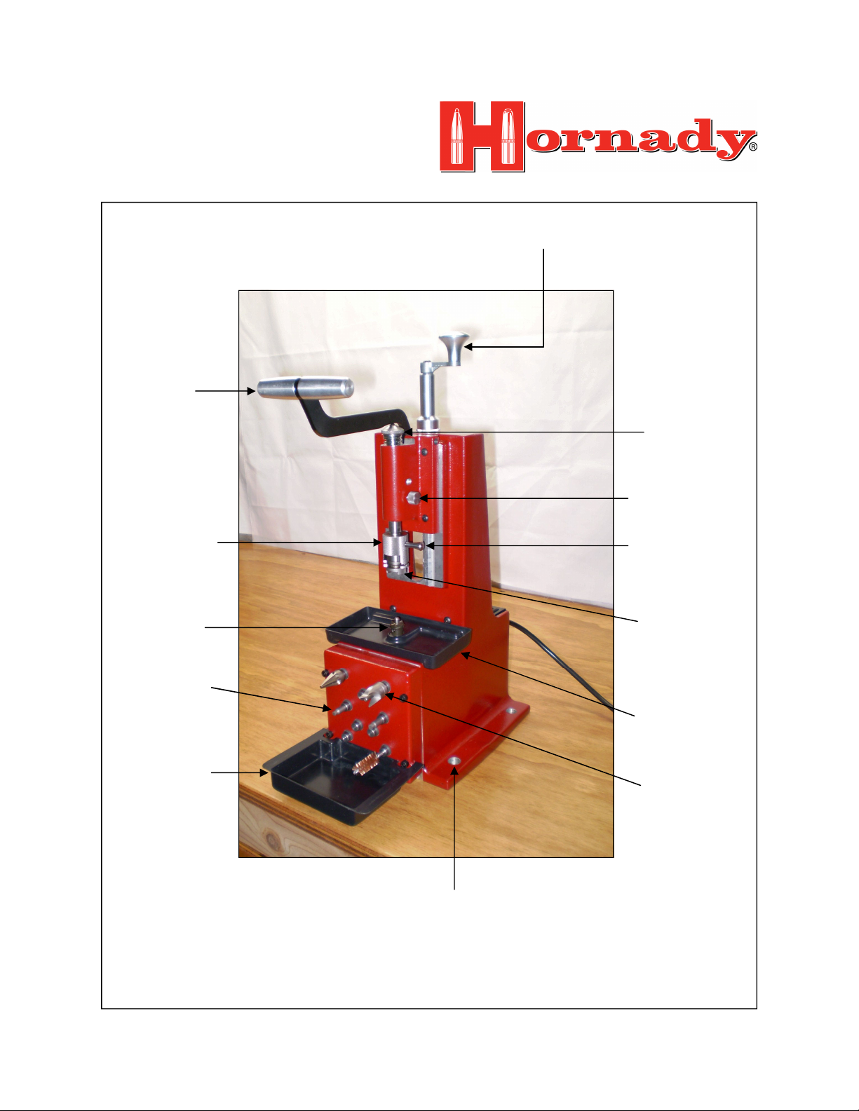
AME & LOCATIO OF MAJOR
PARTS FOR THE HORADY
LOCK--LOAD™ POWER CASE
PREP CETER
T-Handle
Main Adjust Handle
Spindle Stop
Position Screw
Shell Holder
Retainer
Cutting Unit
Case Prep
Tools
Chip Catcher
Cam-Lock™
Handle
Shell Holder
Chip Catcher
Case Prep
Tools
Mounting Base
Page 2

ISTRUCTIOS FOR USIG THE
HORADY LOCK--LOAD™
POWER CASE PREP CETER
Thank you for purchasing the Hornady Lock-NLoad™ Power Case Prep Center. Please read these
instructions before using this machine. If you have
any questions about this machine, contact us at 1-800338-3220.
Product Description:
The Hornady Lock-N-Load™ Power Case Prep Center
features a powered Case Trimmer and six work stations for the following reloading tools: Chamfer Tool,
Deburring Tool, Large & Small Primer Pocket Cleaning Heads and caliber specific case neck brushes. The
Power Case Prep Center may also be used to deburr
flash holes and uniform/ream primer pockets with optional accessories which are sold separately.
The Cam-Lock™ feature on the Hornady Lock-NLoad™ Power Case Prep Center locks the case in a
removable Shell Holder for precise trimming. The
Lock-N-Load™ Power Case Prep Center will only
work with Hornady Shell Holders. (Hornady Shell
Holders are sold separately) The Power Case Prep
Center comes with a 5/64” hex wrench and seven interchangeable pilots to accommodate .22 cal, 6mm,
.270 cal, 7mm, .30 cal, .38 cal and .45 caliber cartridges. Other pilots are available. Caliber specific
pilots are used to align the case mouth on the cutting
unit. The Hornady Lock-N-Load™ Power Case Prep
Center is engineered to help you significantly improve
the efficiency of your reloading process by combining
several essential case prep tools into one unit.
General Information About Case Trimming:
Repeated firing and reloading results in the brass of a
case flowing towards the case mouth. Reloaded cases
grow in length because of these actions. When a case
exceeds its maximum case length, it may contact the
throat of a firearm. If this happens, the case will not
release the bullet properly upon firing and chamber
pressure will subsequently increase. Whenever a case
grows longer than its maximum specified length it
must be trimmed back to a length near the minimum
for that caliber. Trim and maximum case length specifications for modern cartridges are published in the 7th
Edition Hornady Handbook of Cartridge Reloading.
Refer to this handbook for case trim specifications and
other case prep topics.
Safety Precautions:
The Hornady Lock-N-Load™ Power Case Prep Center
has been engineered with your safety in mind. The
likelihood of an injury or property damage is reduced
when these safety precautions are followed.
• Become thoroughly familiar with the machine by
studying these instructions.
• Leave the machine unplugged until you are ready
to prep cases and have read these instructions.
• Do not work on or near damp or wet surfaces.
• Plug power cord into a properly grounded outlet.
• Wear eye protection when operating the Power
Case Prep Center.
• Do not use this machine if you’re rushed for time
and don’t take shortcuts by attempting to bypass
any of these instructions.
The Hornady Lock-N-Load™ Power Case Prep Center
has an in line fuse to protect the motor from damage
when the cutter is under too much load. If you try to
trim off more than .050” at a time really fast you may
put too much load on the motor which will blow the
fuse. The fuse is a 1
glass fuse. You can purchase these at most automotive
or electronic stores. Under normal use, you should
never have to replace the fuse. NEVER USE A FUSE
LARGER THAN 1
Instructions for Powered Case Prep Center:
(1) Secure the Hornady Lock-N-Load™ Power Case
Prep Center to your reloading bench with four 1/2”
diameter bolts, nuts and washers. Select a bolt length
based on the dimensions of your reloading bench.
(2) Before you start trimming, make sure all cases
have been full-length sized or neck sized with a reloading die.
(3) Check to make sure the power cord is NOT
plugged in.
1/4
amp, 1/4” x 1
1/4
AMP.
1/4
” fast acting
Page 3
ISTRUCTIOS FOR USIG THE
HORADY LOCK--LOAD™
POWER CASE PREP CETER
(page 2 of 6)
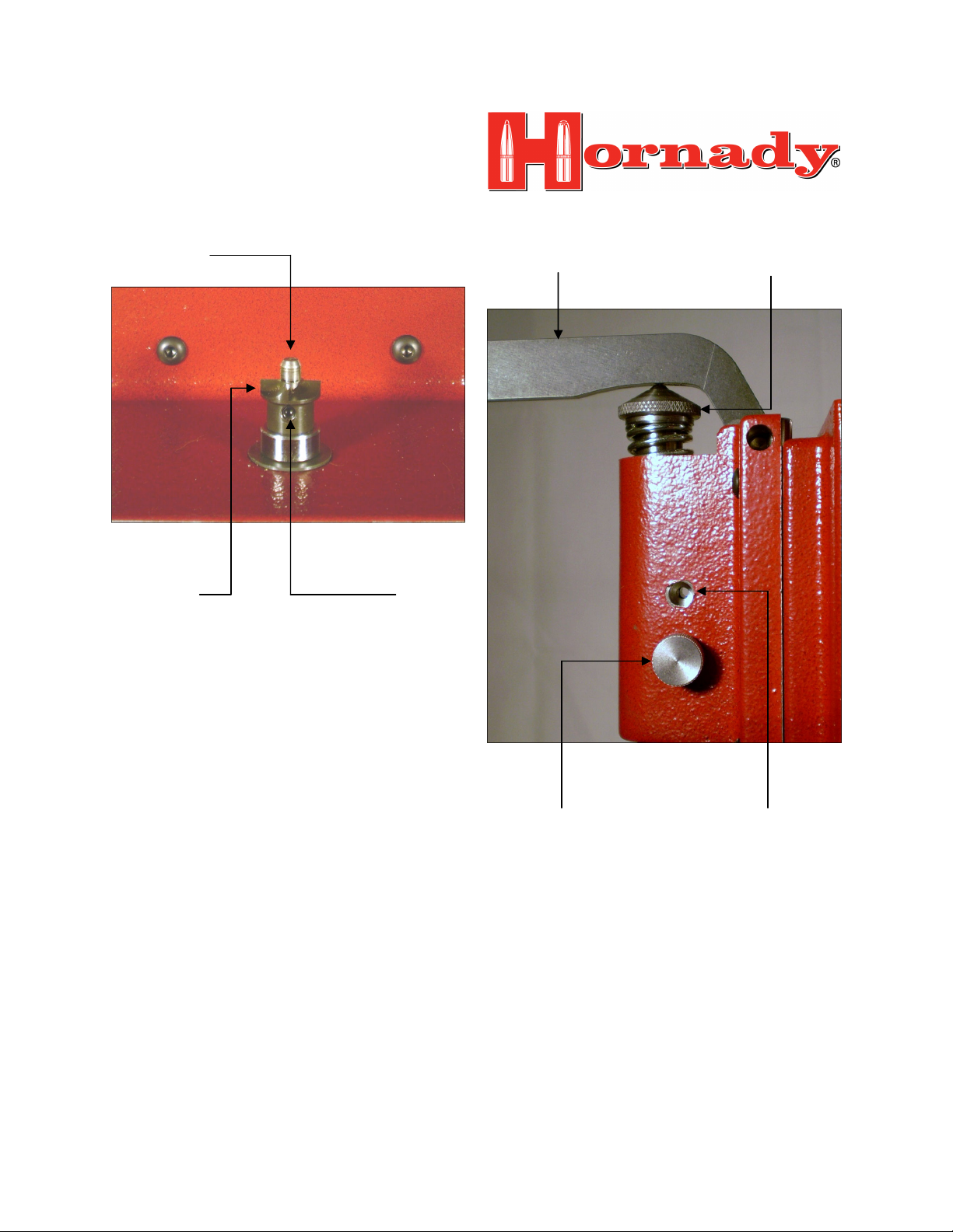
Trimmer Pilot
Fig. 1
Cutting Unit Set Screw
(4) Insert a caliber specific pilot into the cutter. e.g.
use trimmer pilot # 1 for .223 Remington. Tighten
pilot set screw with the 5/64” hex wrench. See Fig. 1.
(5) Loosen Main Adjustment Knob on the back of the
machine and turn the Main Adjust Handle Counter
Clock Wise so there is ample room between the Shell
Holder and Trimmer Pilot. See preceding photo with
name & location of major parts.
When you have installed a caliber specific pilot, focus
your attention on the Position Screw which is located
on the right side of the Spindle Platform. The bottom
hole is used to accommodate short/medium cases and
the upper hole is used for long cases. To check the
initial position of the Shell Holder, insert a case into
the Shell Holder Retainer and rotate it Counter Clock
Wise to lock up the case. The slot in the Shell Holder
should be facing the front of the machine. If it is not,
pull down the T-Handle approximately 1/2” and unscrew the Position Screw. Rotate the Spindle Stop
Clock Wise until the slot in the Shell Holder faces the
front of the machine. Re-install the Position Screw in
the upper or lower hole (Fig. 2).
Chip Catcher is not shown in Fig. 1
Arm of
T-Handle
Fig. 2
Short/Medium Case
Length Position
Note: You may have to move the Spindle Stop Clock
Wise or Counter Clock Wise to realign the Position
Screw with the upper or lower hole. Snug the Position
Screw once it’s in position.
To remove the Shell Holder, screw the Shell Holder
Retainer Clock Wise 1 turn and pull out the Shell
Holder.
(6) Turn the Shell Holder Retainer Clock Wise 1 turn,
pull out the Plunger or the Shell Holder and the
Plunger. Insert the Plunger through the center hole of
the Shell Holder. Check to make sure the O-Ring is
between the Plunger and the Shell Holder. See Fig. 3
on Page 3.
Spindle
Stop
Long Case
Length Position
Page 4

ISTRUCTIOS FOR USIG THE
HORADY LOCK--LOAD™
POWER CASE PREP CETER
(page 3 of 6)
Fig. 3
Spindle
Cam-Lock™ Handle
Shell Holder Retainer
Plunger
O-Ring
Shell Holder
(7) Replace the Shell Holder & Plunger and screw the
Shell Holder Retainer Counter Clock Wise 1 turn.
(8) Guide a case specific Shell Holder into the Shell
Holder Retainer until it snaps into place. e.g. use Hornady Shell Holder # 16 for .223 Remington
(9) Turn the Cam-Lock™ handle Clock Wise until the
Plunger is flush with base of Shell Holder. Insert a
case into the Shell Holder and turn the Cam-Lock™
handle Counter Clock Wise. This will lock the case in
the Shell Holder.
Note: Check to make sure the slot in the Shell Holder
Retainer is facing the front of the machine when you
lock a case up in the Shell Holder.
(10) Loosen the Main Adjustment Knob
(approximately 1/2 turn) and turn the Main Adjust
Handle Counter Clock Wise until the case mouth is
approximately 0.5” above the trimmer pilot with the Thandle in the up position (Fig. 4 & Fig. 5 on page 4).
(11) Tighten the Main Adjustment Knob and lower the
T-handle to determine how much fine adjustment is
needed until the case mouth makes contact with the
trimmer cutter.
Fig. 4
Chip Catcher Accessory
Page 5

ISTRUCTIOS FOR USIG THE
HORADY LOCK--LOAD™
POWER CASE PREP CETER
(page 4 of 6)
Micro Adjust
Handle
Fig. 5
(12) Loosen the Main Adjustment Knob
(approximately 1/2 turn) and turn the Micro Adjust
Handle Clock Wise or Counter Clock Wise until the
case mouth barely touches the trimmer cutter.
Note: Each mark (knurl) on the Micro Adjust Handle
is equivalent to .001” of vertical adjustment.
(13) Tighten the Main Adjustment Knob, plug in the
power cord and press the on switch to start the case
trimmer motor.
Main Adjust
Handle
Main Adjustment Knob
Arm of
T-Handle
Fig. 6
(14) With the case in Shell Holder, lower T-Handle
until it stops on the spindle support and trim case neck
(Fig. 6).
(15) Raise the T-Handle, shut off the motor and remove the case from the Shell Holder by turning CamLock™ handle in a Clock Wise direction.
(16) Measure case length and make adjustments by
loosening the Main Adjustment Knob and turning the
Micro Adjust Handle in a Clock Wise up or Counter
Clock Wise down direction.
(17) Repeat steps 14-16 until desired trim length is
obtained. Make sure the Main Adjustment Knob is
tight when desired trim length is achieved.
Instructions for Powered Case Prep Tools:
Check to make sure the power cord is NOT plugged in
and screw Chamfer Tool, Deburring Tool, Small &
Large Primer Pocket Cleaners, Case Neck Brushes and
optional Flash Hole Deburring Tool and/or Primer
Pocket Reamer into the threaded sockets. You can
arrange the various case prep tools in any manner that
suits your wishes.
Spindle
Stop
Page 6

ISTRUCTIOS FOR USIG THE
HORADY LOCK--LOAD™
POWER CASE PREP CETER
(page 5 of 6)
Plug in the power cord and turn on the motor by pressing the switch on the back of the machine. Sit or stand
directly in front of the Hornady Lock-N-Load™
Power Case Prep Center so you are not working at an
angle.
Use the Primer Pocket Cleaner Heads and the Case
Neck Brush to remove accumulated carbon deposits
and powder residue from your cases after every reloading cycle. These tools are simple to use but we feel it
would be helpful to cover some basic techniques.
To use the Primer Pocket Cleaner Head, grasp a fired
case and guide the primer pocket to the small or large
cleaner head. (use small head for small rifle calibers
e.g. .223 Remington and large head for large rifle calibers. e.g. .243 Winchester) Apply light pressure for
approximately 5 seconds or until carbon deposits are
removed from the primer pocket. When you are satisfied with the condition of the primer pocket use the
wire brush to remove powder residue from the case
neck (Fig. 7).
If your cases require trimming then you will need to
use the Chamfer and Deburring Tools. These tools are
easy to use but we feel it would be helpful to cover the
basic techniques.
Grasp a trimmed case and slowly guide the case mouth
on to the point of Chamfer Tool with light pressure.
Hold the case on the Chamfer Tool for approximately
5 seconds or until the tool produces a very small bevel
on the inner surface of the case mouth. This will make
bullet seating easier (Fig. 7).
When you are satisfied with the bevel on the case
mouth remove the burr from the outer surface of the
case neck by guiding the case mouth to the spindle of
the Deburring Tool. Apply light pressure and hold
case on the Deburring Tool for approximately 5 seconds or until the burrs are removed from the outer surface of the case neck.
Chamfer Tool Deburring Tool
Fig. 7
Chip Catcher
Small & Large
Primer Pocket Cleaners
The optional Flash Hole Deburr Tool and Primer
Pocket Uniformer were developed with the competitive shooter in mind. When most cases are manufactured, a burr is left inside the flash hole. A burr can
cause erratic powder ignition which adversely effects
the accuracy of ammunition. The Flash Hole Deburr
Tool is used to remove small burrs inside the case
which insures more uniform ignition characteristics. If
you wish to remove burrs from your flash holes, insert
the case mouth down the shaft of the tool until it
makes contact with the shoulder of a caliber specific
pilot. Hold the case in this position for approximately
5 seconds or until you feel no resistance between the
cutting blade and the primer pocket.
Case Neck Brush
Page 7

ISTRUCTIOS FOR USIG THE
HORADY LOCK--LOAD™
POWER CASE PREP CETER
(page 6 of 6)
The Primer Pocket Uniformer is designed to cut the
depth of primer pockets to correct SAAMI specifications and remove accumulated carbon deposits
simultaneously. To use this accessory, grasp a fired or
unfired case and guide the primer pocket to the small
or large uniformer. Apply light pressure for approximately 5 seconds or until you are satisfied with the
condition of the primer pocket.
The optional Primer Pocket Reamer was designed for
shooters who recycle military brass for their hand
loaded ammunition. Before you use the Primer Pocket
Reamer make sure you have removed the spent primer
with a full-length die or decapping pin. To use the
tool simply position the primer pocket on the small or
large cutting head and hold it in this position with light
pressure until the crimp has been removed.
 Loading...