

Page 1
OWNER'S MANUAL
®
LOCK-N-LOAD
B ULLET
FEEDER
(PISTOL)
Page 2
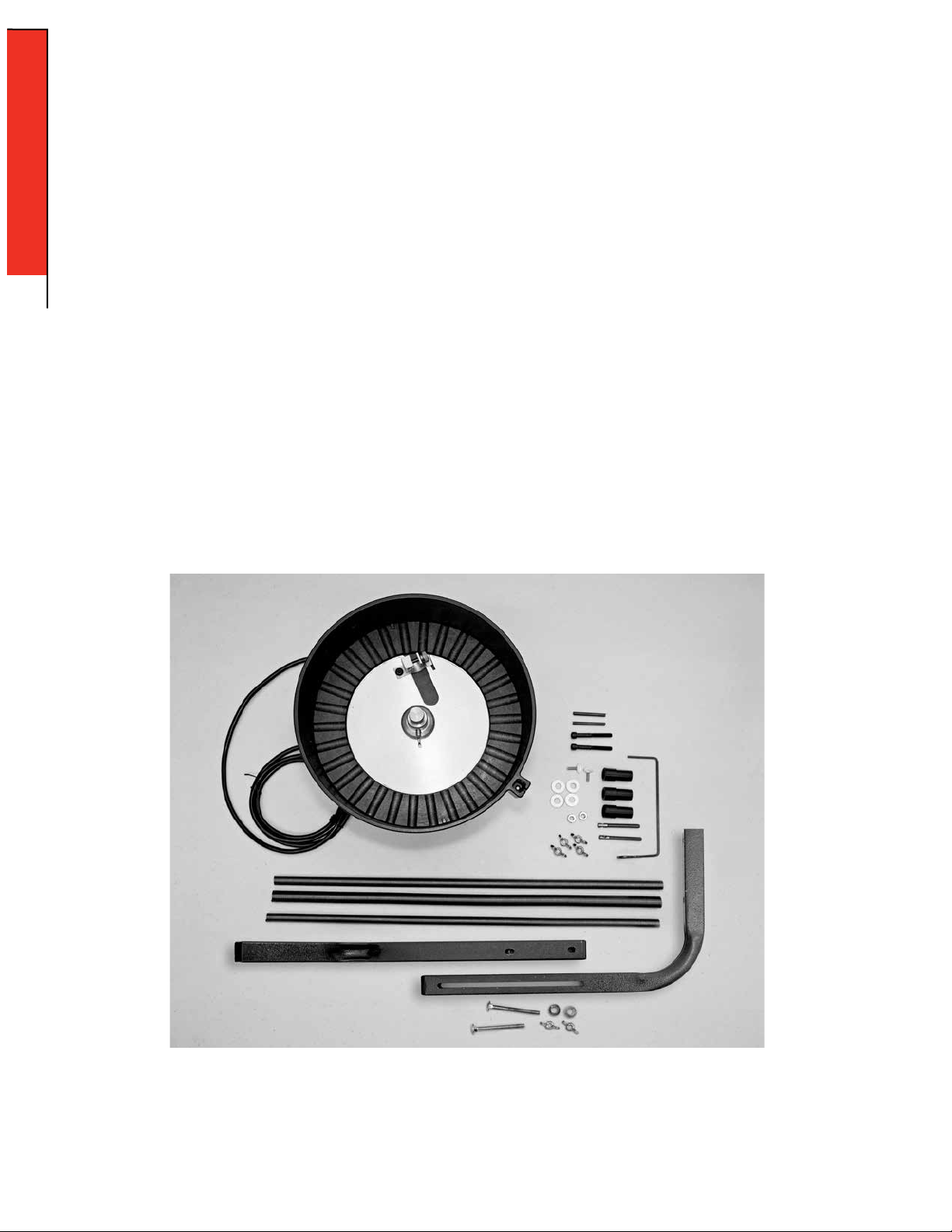
Table of Contents
ASSEMBLY
ASSEMBLY
Pistol Bullet Feeder .......................................................... Page 3
CHANGE-OVERS
The Hornady Lock-N-Load® Pistol Bullet Feeder is capable of feeding most pistol
bullets. Refer to this section when changing bullet caliber, type, or brand.
Pistol Bullet Feeder .......................................................... Page 11
Plate Height
Wiper Adjustment
Drop Tube Funnel
Drop Tube
Bullet Feed Die
APPENDIX
APPENDIX B
Lock-N-Load® AP™ Press Mounting Template .......................... Page 15
- 2 -
ASSEMBLY: PISTOL BULLET FEEDER
Page 3
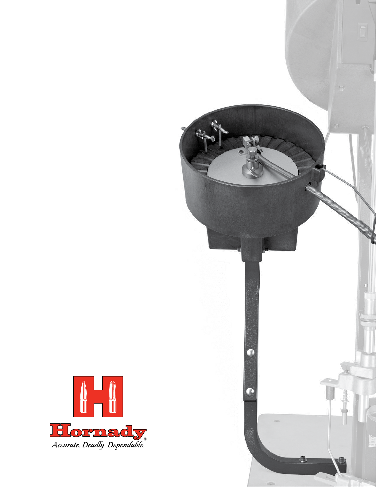
Lock-N-Load® AP™ Pistol Bullet Feeder
OVERVIEW
Your new Lock-N-Load® AP™ Pistol Bullet Feeder has been packaged to ensure minimal vibration and damage during transportation.
Remove all the parts from the packing box (see page 2) and spread them over a large flat surface. Refer to the parts list and exploded view
on the next two pages and check to make sure all necessary parts are identified.
This manual provides step-by-step instructions that make set-up and operation easy and understandable.
ASSEMBLY
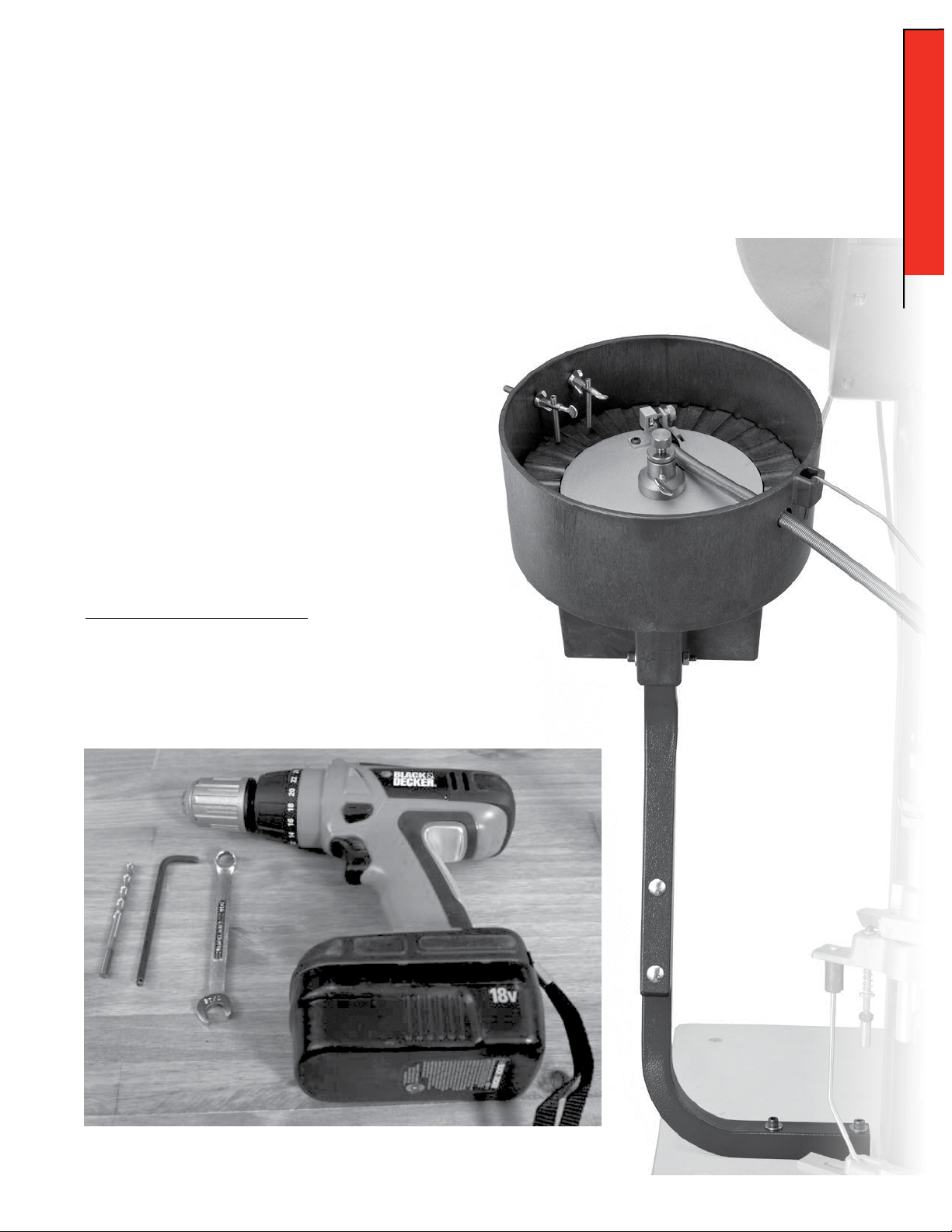
Tools needed for assembly and set-up:
• 7/16" End Wrench
• 3/16" Hex Wrench
• 1/4" Drill Bit
• Electric Drill
ASSEMBLY: PISTOL BULLET FEEDER
- 3 -
Page 4

Lock-N-Load® Auto Progressive (AP™) Pistol Bullet Feeder
PARTS LIST
Production
ASSEMBLY
Item No.
1 392011 3 Nut Hex 10-32 Zinc
2 399209 1 Steel Knurled Thumb Screw
3 399213 1 Tube Spring Clamp
4 399210 1 BHCS 10-32 X 1/4
5 399 214 1 Tube Bullet Drop Funnel Large
5 399215 1 Tube Bullet Drop Funnel Medium
5 399216 1 Tube Bullet Drop Funnel Small
6 399205 1 Screw Adjustment Bullet Feed
7 399206 1 Screw Lock Nut Adjustment
8 398067 1 Rubber Washer Flat
9 399208 1 Center Plate Adjustment Nut
10 398400 1 Thumb Screw 1/4-20 X 1/2
11 399202 1 Hopper Turning Plate
12 398401 2 Screw FHSCS 10-32 X 1/4
13 399201 1 Bullet Feed Wheel - Pistol
Part No. Qty. Description
Item No.
Production
Part No. Qty. Description
20 399102 1 Spur Gear 1.200 P.D. 24 Tooth
21 39924 4 1 FHCS 1/4-20 X 1/2
22 398381 1 Pin Spirol 1/8 X 3/4
23 398399 1 Motor Bullet Feeder
24 399222 2 Screw Bullet Wiper
25 399242 6 Nut Wing 1/4-20
26 399223 2 Spring Wiper Bullet Feed
27 399224 2 Thumb Screw 8-32 X 1/2
28 399217 1 Tube Holder Bullet Feeder
29 399200 1 Bullet Feed Hopper
30 399211 2 SHCS 1/4-20 X 2
31 39 0128 6 Washer Flat 1/4"
32 398418 1 Bushing (HEYCO 1147) Black
33 399219 1 Tube Drop Small
33 399243 1 Tube Drop Medium
14 399212 3 Nut Hex 1/4-20
15 399207 1 Center Pin Bullet Plate
16 399218 1 Spur Gear 1.500 P.D., 30 Tooth
17 398313 8 Screw FHSCS 10-32 X 3/4
18 399203 1 Bullet Feeder Base Plate
19 398402 1 Ideler Gear Shaft
33 399221 1 Tube Drop Large
34 398332 1 Switch 2 Position
36 399358 1 Support Tube-Bottom
37 399359 1 Support Tube-Top
38 399360 2 1" Square Finishing Plug
39 399362 2 1/4-20x2.5 Carriage Bolt
- 4 -
ASSEMBLY: PISTOL BULLET FEEDER
Page 5
Lock-N-Load® AP™ Pistol Bullet Feeder
EXPLODED VIEW
ASSEMBLY
ASSEMBLY: PISTOL BULLET FEEDER
- 5 -
Page 6

Mounting the Bullet Feeder
1
to the Bench
Refer to Appendix B for the template.
1
ASSEMBLY
Place the template on the table in the location you would
like to mount the press and Lock-N-Load® AP™ Pistol Bullet
Feeder. Drill ¼" holes for the placement of the Square Tubing
Mounting Bracket.
Use ¼" bolts with ¼" Flat Washers (not provided, due to
2
different thicknesses of tables) on top of the Square Tubing
Mounting Bracket and also one on the bottom of the bench.
2
Once the Support Tube-Bottom (36) is securely attached to
3
the bench top, line up the Support Tube-Top on the front of
the tube, oriented as shown in the exploded view on page 27.
Slide a ¼-20x2.5 Carriage Bolt (39) through one of the square
holes in the top tube and through the slot in the bottom tube.
Place a ¼” Flat Washer (31) over the bolt and thread on a
¼-20 Wing Nut (25). Repeat with another bolt, washer, and
nut through the other square hole. The height of this tube
may need to be adjusted at a later time in order to allow
bullets to slide freely down the Drop Tube (33).
- 6 -
ASSEMBLY: PISTOL BULLET FEEDER
Page 7

Mounting the Bullet Feed Hopper to the
Square Tubing Mounting Bracket
Slide the Hopper (29) over the top of the Square Tubing
4
Mounting Bracket (37), with the open face of the Hopper facing
the front of the bench or table.
Place a ¼-20 X 2 SHCS Bolt (30) with one ¼" Flat Washer (31)
5
through the top hole of the Bullet Feed Hopper and the Square
Tubing Bracket.
4
ASSEMBLY
Square Tubing
Bracket
5
SHCS Bolt
Place a ¼-20 X 2 SHCS Bolt (30) with one ¼" Flat Washer
6
(31) through the bottom hole of the Bullet Feed Hopper and
the Square Tubing Mounting Bracket.
If you are having issues with bullets not being able to keep
up feeding (approximately 100 bullets in 5 to 6 minutes),
switch the bolt from the bottom hole to the middle hole.
Flat Washer
6
SHCS Bolt
Flat Washer
ASSEMBLY: PISTOL BULLET FEEDER
- 7 -
Page 8

Place a ¼" Flat Washer (31) over the end of each of the two
7
Bolts just previously place through the Bullet Feed Hopper
and Square Tubing Mounting Bracket.
Place a ¼-20 Hex Nut (14) onto the two ¼-20 X 2 SHCS Bolts
and tighten snug.
7
ASSEMBLY
Tighten Hex Nut
Bullet Feed Hopper Set Up
Loosen ¼-20 Thumb Screw (10).
8
8
Loosen Lock Nut (7) on the Adjustment Screw (6).
9
Thumb Screw
9
Adjustment
Screw
Lock Nut
- 8 -
ASSEMBLY: PISTOL BULLET FEEDER
Page 9

Bullet Feed Hopper Set Up (con't)
10
Raise the Hopper Turning Plate (11) by turning the
10
Adjustment Screw (6) clockwise.
Raise the Bullet Guide Plate above the bottom of the slots
on the Bullet Feed Wheel Pistol far enough to hold a bullet
base first against the Bullet Feed Wheel Pistol.
Place a bullet that you plan on loading facing base first up
11
against the Bullet Guide Plate and against the Bullet Feed
Wheel Pistol. Next to this bullet, place another bullet so that
the nose is facing the center of the Bullet Feed Wheel Pistol.
You will then need to adjust the Bullet Guide Plate either
up or down to get a bullet to stay on the Bullet Feed Wheel
Pistol base first, but fall off the Bullet Feed Wheel Pistol
if the bullet is nose first towards center of the Bullet Feed
Wheel Pistol.
ASSEMBLY
Adjustment
Screw
Hopper Turning
Plate
11
Bullet Feed
Wheel Pistol
Bullet Wiper (Bottom Wiper)
Install the wipers as with one Wing Nut
outside of the Bullet Feed Hopper on the Wiper Screw
12
Loosen the wing nuts.
Place two bullets nose to nose in a slot close to the height
of the first or bottom wiper screw and Wiper Spring (26).
Adjust the first wiper spring and screw to wipe off the
outside bullet.
Tighten down the two wing nuts and the thumb screw.
(25)
installed on the
(24)
Bullet Guide
Plate
12
.
Hopper
Wiper Screw
Wing Nuts
Wiper Spring
ASSEMBLY: PISTOL BULLET FEEDER
- 9 -
Page 10

Bullet Wiper (Top Wiper)
13
Wing Nuts
Install the wipers as shown in with one Wing Nut installed on
13
the outside of the Bullet Feed Hopper) on the Wiper Screw.
Place one bullet facing the center of the Bullet Feed Wheel
ASSEMBLY
Pistol base first. Next to it, place a bullet facing nose first
to the center of Bullet Feed Wheel Pistol. The bullet that is
facing nose first, push the nose down a little so the base
is sticking up.
Adjust the second Wiper Spring and Wiper Screw to just
miss the nose of the first bullet but kick the base of the
second bullet.
Tighten down the two Wing Nuts and the Thumb Screw.
Drop Funnel
Select the correct size of Drop Funnel for your application.
14
9MM/38/.357 ...........(375 I.D.) ............Item No. 399216
40 S&W/10 MM ........(406 I.D.) ............Item No. 399215
.44/.451/.452 ............ (530 I.D.) ............Item No. 399214
14
Wiper Screw
Wiper Spring
Thumb Screw
Insert the Drop Funnel (5) into Tube Spring Clamp (3). You will
15
want the front edge (outside edge) of the Drop Funnel as close
to the Bullet Feed Wheel Pistol without touching the Bullet Feed
Wheel Pistol.
Tighten the Knurled Thumb Screw (2) on the side of the Tube
Spring Clamp. Only snug this screw, DO NOT over tighten this
screw.
- 10 -
ASSEMBLY: PISTOL BULLET FEEDER
15
Bullet Feed
Wheel Pistol
Knurled Thumb
Screw
Tube Spring
Clamp
Drop Funnel
Page 11

Setup / Changeover of the Lock-N-Load® Pistol Bullet Feeder
The Hornady Lock-N-Load® Pistol Bullet Feeder is capable of feeding most pistol bullets. When changing bullet caliber, type, or brand, the
following components on the Bullet Feeder may need to be changed or verified. Hopper Plate Height.
• Bottom Wiper Location
• Top Wiper Location
• Drop Tube Funnel
• Drop Tube
• Bullet Feeder Dies
Hopper Plate Height
1
Loosen ¼-20 Thumb Screw and the Lock Nut on the
Adjustment Screw.
Raise the Bullet Guide Plate by turning the Adjustment Screw
clockwise.
Raise the Bullet Guide Plate above the bottom of the slots on
the Bullet Feed Wheel Pistol far enough to hold a bullet base
first against the Bullet Feed Wheel Pistol.
Place two bullets onto the Bullet Feed Wheel, one with the
2
nose toward the center, and the other with the base toward
the center. Rotate the Adjustment Screw to adjust the Bullet
Guide Plate either up or down to get a the nose down bullet to
fall off the plate, yet keep the base down bullet on the Bullet
Guide Plate.
Once the Bullet Guide Plate position is acceptable, tighten
the Lock Nut and then the ¼-20 Thumb Screw.
1
Adjustment Screw
Thumb Screw
2
Bullet Feed Wheel
Lock Nut
Adjusting the Bottom Wiper
3
The bottom wiper is used to remove the top bullet when two
bullets are double-stacked on the Feed Wheel Plate.
To adjust the spring location, loosen the two Wing Nuts and
slide the assembly in or out. The spring should be located so
the top bullet is knocked off the bottom bullet as the Bullet
Feed Wheel turns. Tighten down the two wing nuts and the
thumb screw.
Loosen the thumb screw and move the spring so that it just
clears the Bullet Feed Wheel. The spring should not contact
the Feed Wheel Plate during normal operation.
With a little trial and error, the spring should be adjusted
so that it knocks off the top bullet without disturbing the
bottom bullet.
CHANGE-OVER
3
Wing Nut
Wing Nut
Thumb Screw
CHANGE-OVER: PISTOL BULLET FEEDER
- 11 -
Page 12

Adjusting the Top Wiper
4
The Top Wiper is intended to remove nose heavy bullets that do
not fall off when pointed nose down on the Bullet Feed Plate .
Place two bullets onto the Bullet Feed Wheel near the Top
Wiper, one with the nose toward the center, and the other with
the base toward the center. Push the nose down a little on the
bullet that is nose toward so the base is sticking up.
Adjust the second wiper spring and wiper screw to just miss
the nose of the first bullet but kick the base of the second
bullet.
Tighten down the two wing nuts and the thumb screw.
Switching Drop Tube Funnel
5
Select the correct size of Drop Funnel for your application.
9MM/38/.357 .............. (375 I.D.) .......... Item No. 399216
40 S&W/10 MM ........... (406 I.D.) ..........Item No. 399215
.44/.451/.452 .............. (530 I.D.) ..........Item No. 399214
Insert the Drop Funnel into Tube Spring Clamp. You will want
the front edge (outside edge) of the Drop Funnel as close to the
Bullet Feed Wheel Pistol without touching the Bullet Feed Wheel
Pistol.
Tighten the Knurled Thumb Screw on the side of the Tube
Spring Clamp. Only snug this screw, DO NOT over tighten this
screw.
4
Wiper Screw
Wiper Spring
5
Wing Nut
Thumb Screw
Tube Spring
Clamp
Knurled Thumb
Screw
Drop Tube Funnel
Switching the Drop Tube
6
Select the correct size of Drop Tube for your application.
9MM/38/.357 .............. (375 I.D.) .......... Item No. 399219
40 S&W ....................... (406 I.D.) ..........Item No. 399243
.44/.451/.452 .............. (530 I.D.) ..........Item No. 399221
Slip the Drop Tube into the hole on the bottom right side of the
Bullet Feed Hopper. Insert the end of the Drop Tube into the
back end of the Drop Funnel. Insert the straight end of the Drop
Tube Holder into the hole on the bottom right side of the hopper.
CHANGE-OVER
Next place the Drop Tube into the hook of Drop Tube Holder.
Testing Hopper Setup
7
At this time, place about 100 bullets into the Bullet Feed
Hopper and turn on the Switch on the bottom right corner of the
Bullet Feed Hopper.
You will want to hold the end of the Drop Tube in your hand at
this time to catch the bullets that will fall out of the tube.
At this time, make sure you have the Bullet Wipers set correctly.
If they are not, shut off the Switch and readjust the Bullet
Wipers. You may need to do this a couple of times, until you
have them set correctly and the bullets are falling base first
every time.
If the hopper plate is jumping or not rotating smoothly, your
Drop Tube Funnel is too close to the Bullet Feed Wheel Pistol.
This needs backed off until the Bullet Feed Wheel Pistol rotates
smoothly.
If the bullets are feeding correctly, tighten down the Bullet
Guide Plate Thumb Screw, and Snug Lock Nut.
6
Drop Tube Funnel
Drop Tube
7
Drop Tube Funnel
Drop Tube
- 12 -
CHANGE-OVER: PISTOL BULLET FEEDER
Page 13

Bullet Feed Die Set Up
Disassemble the die and lay the parts out on a flat surface.
Degrease every part of the die.
Reassemble the die as you took it apart.
Collet “A” goes in first with the open slots facing the bottom
of the die.
Collet “B” goes in next with the open slots facing the bottom
of the die.
Thread the Lock Ring back onto the Adjustment Screw until
the Lock Ring is near the top end of the Adjustment Screw.
Place the O-Ring over the threads of the Adjustment Screw
until it is close to the Lock Ring.
Screw the Adjustment Screw into the die. Screw it down until
the end of the Adjustment Screw is just touching “Collet B”.
With the Adjustment Screw touching the top Collet, back the
Adjustment Screw off ½ turn and lock down the Lock Ring
against the top of the Die Body.
At this time you should be able to shake the die and hear the
two Collets move up and down just a little bit. If you hear
this, the die is set up correctly.
Adjustment Screw
Lock Ring
Collet “B”
O-Ring
Collet “A”
Die Adjustment Lock-N-Load® AP
Screw on the Lock Ring to the outside threads of the Die Body.
Screw on the Lock-N-Load® Bushing to the outside threads of
the Die Body.
Place the die into the top of the press and inserting it into
the Lock-N-Load® Bushing in the Press Body.
Die Adjustment for a NON Lock-N-Load® AP
Place a Flared Case for your set up in the previous station.
Case mouths should be flared to the approximate dimensions
listed below.
380/9MM ................. .385"
38/357 ...................... .387"
40S&W/10MM ........... .430"
44 SPL/44 MAG ......... .460"
.451/.452 ................... .481"
Raise the ram to the top of the stroke.
Screw the Die Body down until it touches the top of the case.
Lower the ram to the bottom of the stroke.
Screw the Die Body down ½ turn and lock down the Lock Ring.
At this time the die should be set.
Place 5 or 6 bullets base first into the top of the die.
™
™
CHANGE-OVER
Bullet Feeder Die
Die Set Up
Place the case into the Shell Plate in the station before the Bullet Feeder Die
so when the press rotates, the Flared Case will be inserting into the Bullet
Feeder Die. Continue to raise the Ram to the top of the stroke. You will not be
able to see or hear anything at this time.
Lower the Ram slowly.
You should be able to see a bullet that dropped on top of the case mouth. If
the bullet dropped onto the case mouth and you can see it, you should have
been able to hear a little noise coming from the collets. This is a correct
sound, it will do this every time that the collets work correctly.
If the collets didn’t drop a bullet, lower the Die Body approximately 1/16"
turn and repeat the previous 3 steps. Repeat these steps until you get a
bullet to fall onto the case every time.
CHANGE-OVER: PISTOL BULLET FEEDER
- 13 -
Page 14

- 14 -
Page 15

APPENDIX B - TEMPLATE Lock-N-Load® AP
™
- 15 -
Page 16

P.O. Box 1848, Grand Island, Nebraska 68802-1848
308-382-1390 • 800-338-3220 • Fax: 308-382-5761
399176 03/2014
www.hornady.com • webmaster@hornady.com
 Loading...