

Page 1
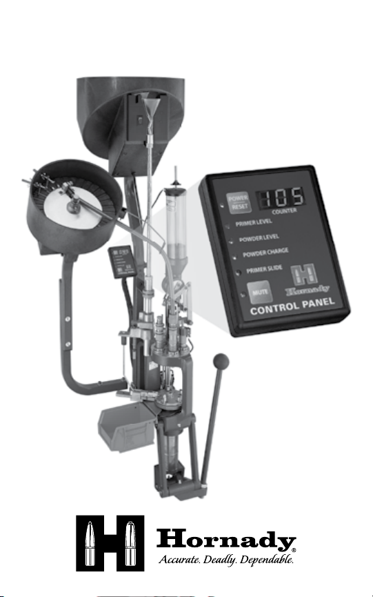
LOCK-N-LOAD
®
CONTROL PANEL
Deluxe Control Panel
Item No. 044650
Standard Control Panel
Item No. 044651
Page 2

TABLE OF CONTENTS
Warnings .........................................................2
Item s in Box ......................................................2
Setup and Operation...............................................3
Control Panel Setup .............................................3
Counter and Slide Detect Sensor Setup ...........................4
Powder Level Check Setup .......................................5
Powder Safeguard Die Setup .....................................5
Primer Level Check Setup ........................................6
FAQ ..............................................................7
Warranty .........................................................8
Product Registration ..............................................8
Specifications ....................................................8
WARNINGS
• Use in dr y locations.
• Unplug when not in use.
• When properly set , the Powder Safeguard Die will detect
double charges or no charge. Verif y actual charge weight periodically
wit h a quality scale.
DELUXE
CONTROL PANEL
ITEMS IN BOX
• Control Panel
• 12V 1.0A Power Supply
• MountingBracket
and Thumbscrew
• 12V Lock-N-Load Light Strip
• Wire Harness
• Counter and Primer
Slide Sensor
• Powder Level Sensor
• Primer Level Sensor
• Powder Safeguard Die
• Manual
• Product Registration Card
2
STANDARD
CONTROL PANEL
ITEMS IN BOX
• Control Panel
• 12V 1.0A Power Supply
• MountingBracket
and Thumbscrew
• Wire Harness
• Counter and Primer
Slide Sensor
• Manual
• Product Registration Card
Page 3
SETUP AND OPERATION
CONTROL PANEL SETUP (Deluxe & Standard models)
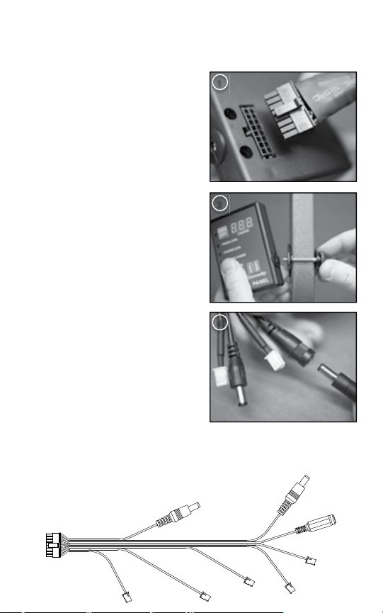
1) Align wire harness with
connec tor on back of the
Control Panel. Firmly press wire
harness into Control Panel while
supporting Control Panel.
2) Slide C ontrol Panel Mounting
Bracket onto t he Case
Feeder Tube.
3) Place T humbscrew through
Control Panel Mounting Bracket
and tighten Thumbscrew.
NOTE: Do not overtighten
thumbscrew.
4) Plug 12V power supply into input
power jack on the wire harness.
OPERATION
• Press and hold POW ER button to
power on the Control Panel.
• Press and hold POW ER
but ton for 6 seconds to power
off the Con trol Panel.
• Press the POWER but ton
momen tarily to reset the counter.
• Press MU TE button to silence
audible alarm (green light = unmuted, and red light = mu ted).
NOTE: When the Control Panel is muted, the sensor lights will still turn from
green to red when a sensor is activated, but no audible alarm will be heard.
1
3
4
WIRE HARNESS
REFER ENCE VIEW
(not to scale)
Cont rol Panel
Connector
Prim er
Level
12V Ou tput
Power
Jack
Powde r
Level
12V Ou tput
Power
Jack
Powde r
Charge
12V Inp ut
Power J ack
Prim er Slide De tect
Cycle Counter
3
Page 4

COUNTER AND SLIDE DETEC T SENSOR SETUP
(Deluxe & Standard models)
1) Verify reloading press is securely
mounted to bench with two bolts.
Remove the right bolt near the
primer feed/subplate, and insert
the bolt through the Counter
Bracket. Rotate t he bracket until
the sensor levers align with the
subplate and primer slide.
NOTE: It is helpful to use the
Primer Follower to lock the Primer
Slide back to help set the Primer
Slide Switch.
2) Tighten the bracket dow n once
the Sensors are aligned.
3) Plug t he wire harness into each
of the sensors using the two
white connectors near the 12 V
input plug.
4) Verify the wire harness is
plugged in correctly by activating
the sensor and verif ying the
corresponding light turns from
green to red (or the counter
increases by one).
NOTE: If the sensors do not
activate, the lever may be bent up
slightly by pressing down on the
lever near the housing and lifting
up on the end of the lever.
1
2
3
OPERATION
• Counter – When cycling the press (including fully returning the
handle as if seat ing a primer), the counter should increase with
each cycle.
• Primer Slide – W hen the primer slide is held back from either the Pr imer
Follower Rod dropping into the slide, or a jammed primer, the green
light on the Control Panel should turn to red at the bottom of the cycle.
4
Page 5

POWDER LEVEL CHECK SETUP (Deluxe model only)
1) Place the Powder Level assembly
into the powder hopper.
2) Locate the wire lead for the
Powder Detec t Sensor and plug
the wire harness into the sensors.
3) Verify the wire harness is
plugged in correctly by activating
the sensor and verif ying the
corresponding light turns from
green to red on the Control Panel.
4) Adjus t the Stop up or down on the Powder Float to the desired level by
sliding the o-rings on each side of the Stop up or down.
OPERATION
• When t he level of powder becomes low, the stop on t he top of
the Powder Float should trip the sensor.
2
POWDER SAFEGUARD DIE SETUP (Deluxe model only)
1) Ins tall Lock-N-Load bushing
(sold separately) onto Powder
Safeguard Die.
2) Screw t he brass tip nearly all the way
onto the stem by holding the t ip and
top knurl.
3) Cycle press t o hold at the top of
the stroke (the shellplate is as high
as possible).
4) Install Powder Safeguard Die into
the press nex t to the powder drop.
Screw down the Powder Safeguard
Die until approximately
1
⁄8” above the
shell plate.
5) Place a case with t he correct
powder charge under the safe guard die. Begin to cycle the press until
resistance is met. The press should lock up (not continue through a
full cycle).
6) Unscrew the brass tip slight ly, while holding the top knurl, and tr y
to cycle the press again. Repeat until t he press cycles. Unscrew an
additional turn and verif y press cycles.
1
5
Page 6

7) Place an empt y case under the Powder Safeguard Die and cycle the
press until resistance is met. The press should not cycle on an empt y
case. Remove case from press before proceeding.
8) Place a double- charged case under the Powder Safeguard Die and cycle
the press until resistance is met . The press should not cycle on a double
powder charged case. Remove case from press before proceeding.
9) If us ing with t he Contr ol Panel, locate the Powder C harge Detec t lead on
the wire harness, and plug it into the sensor on the Pow der Safeguard Die.
10) Verify the wire harness is plugged in correctly by activating the sensor
and verify ing the corresponding light turns from green to red on the
Control Panel.
OPERATION
• Under normal operation, the press should cycle freely when t he correct
charge is dropped into the case.
NOTE: The Powder Safeguard Die is designed to detect no-charge or
double-charge cases only. It will not detect slight changes to the powder
charge. Periodically check the powder charge weight on a quality scale.
• If press locks up, remove case from press and verify all s tations.
If the shell plate cycled before locking up, each case will need to be
moved back one station before proceeding.
PRIMER LEVEL CHECK SETUP (Deluxe model only)
1) Locate the wire lead for the
Primer Detect Sensor. Slide the
wire harness connector bet ween
the Primer Level Check Mounting
Bracket and the 4 -40 Screw. Plug
the wire harness into the sensors.
A small blunt object may help fully
seating the connector.
NOTE: If the wire connector does
not easily snap into the sensor,
the sensor can be removed via the
two phillips head screws. After connecting the sensor to the harness,
the sensor canbe re-installed.
2) Verif y the wire harness is plugged in correctly by activating the sensor
and verify ing the corresponding light turns from green to red.
3) Slide the Primer Level Check Mounting Bracket over the Primer Housing
Tube until the notch in the Mount ing Bracket is fl ush with the top of the
black plastic Primer Tube Suppor t. Verif y the bracket does not inter fere
wit h the LNL Powder Drop.
6
1
Page 7

NOTE: If mounting on a Dillon
press, please contact Hornady at
1-800-338-3220 and request part
number 399274.
4) Lig htly ti ghten th e bracket dow n using
1
⁄16” hex wre nch and a ¼” open end
a
3
4
wren ch on the bot tom 4 -40 Scr ew and nut .
5) Adjust t he Stop up or down on the
Primer Follower rod to the correct
level by sliding the o-rings on each
side of the stop up or dow n.
OPERATION
• When the level of primers become
low, the stop on the top of the Primer
Follower Rod should trip the sensor.
FAQ
WILL THE CONTROL PANEL F IT ON OTHER PRESSES?
• The Control Panel mount ing bracket is designed to fi t onto a 1”
square tubing, however, it may be mounted onto other surfaces using
the through holes on the mounting bracket.
• The Counter and Primer Slide Sensor are not designed to fi t on
other presses.
• The Primer Level Check will fi t onto an RCBS primer tube. If the Primer
Level Check will be used on a Dillon press, please call Hornady Mfg.
at 1-800 -338-3 220 and request part number 399274.
• The Powder L evel Check is designed t o fi t on both a standard RCBS
and Dillon powder hopper.
• The Hornady Safeguard Die is designed to fi t on any press with a
7
⁄8”–14 thread.
CAN THE CONTROL PANEL B E MOUNTED
ONTO A LOCK- N-LO AD
®
AP™ WITHOUT A
CASE FEEDE R?
• Yes, Hor nady recommends
attaching the Control Panel
using t he through holes in the
mounting bracket, and Case Feeder
¼”–2 0 mounting holes on t he back of
the Lock-N-Load
®
™
AP.
7
Page 8

WARRANTY
Hornady electronic components are covered by a one-year warrant y from t he
date of purchase.
All tool ret urn claims must have a Return Au thorization (RA) number assigned
before acceptance at our facility for further examination. Please DO
NOT send tool i tems without ob taining a R A number from our customer
service staff.
All tool warranty claims are handled on a case-by-case basis. In order
to ini tiate a claim, please con tact our Customer Service Technicians
at 800-338-3220.
PRODUCT REGISTRATION
Please register your product at hornady.com to ensure receipt of product
updates, recalls or ot her pertinent information related to this product.
SPECIFICATIONS
• Model: 04 46 50 (Deluxe) or 044651 (Standard)
• Power Input: 12V DC 1.0A
• Power Output: 12V DC 0.5 A
1-308-38 2-1390 | PO Box 1848 | Grand Island, NE 68 802 | hornady.com
680029
 Loading...