

Page 1

OWNER'S MANUAL
®
LOCK-N-LOAD
CASE
FEEDER
Page 2

Table of Contents
ASSEMBLY ............................................................... Page 3
CHANGE-OVERS ................................................... Page 13
The Hornady® Lock-N-Load® Case Feeder is capable of feeding both pistol and
rifle cases. When changing cartridges refer to this section.
Feed Plate
Feed Tube
Pivot Adapter/Pivot Adapter Bushing
Drop Tube
V-Block
Adjustments
Case Feed Door Adjustment
TROUBLE SHOOTING ........................................ Page 15
- 2 -
See pages 4-5See pages 4-5
See pages 4-5
Page 3

Lock-N-Load® AP™ Case Feeder
OVERVIEW
Your new AP™ Case Feeder has been packaged to insure minimal vibration and damage during transportation.
Remove all the parts from the packing box (see page 2) and spread them out over a large flat surface. Refer to the Lock-N-Load® Case Feeder
parts list and exploded view on the next two pages to make sure all necessary parts are identified.
The manual provides step-by-step instructions and suggestions that make set-up and operation easy and understandable.
NOTE: Everything is designed and machined to fit easily together without modification. If you find that it is necessary to force parts together, stop
and check the instructions and illustrations we have provided.
List of needed hand tools:
• 3/8" wrench
• 7/16" wrench
• 9/16" wrench
• 1/8" Allen wrench
If your AP™ press has a cartridge box bracket that mounts
1
on top of the press, it will need to be changed out for the
Main Bracket (42). To do this, unbolt the press from the
bench top, remove the old cartridge box bracket, and slide
the new Main Bracket under the press so the two raised
holes fit into the press mounting holes (see exploded view
for correct orientation). Re-mount the press to the bench
top using the same hardware that was previously used to
bolt the press down.
• 5/32" Allen wrench
• 3/16" Allen wrench
• Pliers or vise grips
• Small hammer
1
ASSEMBLY
Assembling the 2-pc Square Tubing.
Place Lower Case Feeder Stand next to mounting holes on
2
the back of the AP™ press to determine proper orientation of
the Lower Case Feeder Stand. Once the “top” of the Lower
Case Feeder Stand has been determined, place the Lower
Case Feeder Stand onto a block of scrap wood. Next insert
the Tube Connector into the Lower Case Feeder Stand until
the holes align. Place the Feed Tube Mounting Bracket onto
the Lower Case Feeder Stand so the Feed Tube Mounting
bracket is on the open end of the Tube Connector (see
photo). Place a ¼-20 x 1.5" bolt through the Feed Tube
Mounting bracket and Lower Case Feeder Stand and loosely
attach the flat washer, lock washer, and nut.
Place Upper Case Feeder Stand over the Tube Connector
until it touches the Lower Case Feeder Stand. Place a
¼-20 x 1.5" bolt through the Feed Tube Mounting bracket
and Upper Case Feeder Stand and securely attach the flat
washer, lock washer, and nut. Tighten the lower nut in the
Lower Case Feeder Stand.
Attach assembly onto AP™ Press.
2
Tube connector
Lower
Case
Feeder
Stand
CORRECT ASSEMBLY
Upper Case
Feeder Stand
INCORRECT ASSEMBLY
Tube connector
Feed Tube
Mounting Bracket
ASSEMBLY: CASE FEEDER
- 3 -
Page 4

Lock-N-Load® Auto Progressive (AP™) Case Feeder
PARTS LIST
Production
ASSEMBLY
Item No.
1 398441 1 Case Feed Bowl
2 398 313 4 10-32 x ¾ FHSCS
4 398445 4 8-32 x 3/4 Screw
5 398443 1 Case Feed Funnel Front
6 398375 2 4-40 Hex Head Lock Nut
7 398333 1 Micro Switch
8 398442 1 Case Feed Funnel Back
9 398376 2 4-40 x 5/8 BHSCS
10 398332 1 Rocker Switch
11 398331 1 Motor
12 398444 1 Motor Cover
13 398320 1 Feed Tube-Large
14 398321 1 Feed Tube-Small
15 398303 1 Feed Tube End-Large
16 398446 1 Feed Tube Mounting Bracket
17 396440 2 Lock Ring
18 398298 1 Pivot Adapter
19 398290 1 Pivot
20 398310 1 1/4 - 3/4 Shoulder Bolt
21 398311 1 3 /0 x 3/4 Taper Pin
22 398305 1 Drop Tube-Large
23 398288 1 Spring, Torsion
24 398317 1 Push Rod
25 398371 1 Push Rod Tip
26 390178 3 1/4-20 Hex Head Nut
27 398349 1 Push Rod Bushing
28 398364 1 10 x 1/2 Sheet Metal Screw Pan Head Phillips
29 398344 1 Pivot Body
30 398363 1 Push Rod Spring
31 398343 1 Cam Wire Support
32 398425 1 E Clip 1/4
33 398373 1 Push Rod Nut
34 398372 1 Push Rod Lower
37 398285 1 Case Feed Door Adjustment
38 398291 1 Case Slide
Part No. Qty. Description
Item No.
Production
Part No. Qty. Description
39 398307 1 Case Slide Rod Guide
40 398308 1 Case Slide Rod Guide Spring
41 392011 2 10-32 Hex Head Nut
42 398289 1 Main Bracket
43 398299 1 Cam Wire
47 398321 2 1/4-20 x 125 SHCS
48 390128 5 1/4 Flat Washer Zinc Plated
49 3920 31 2 1/4" Lock Washer
50 398304 1 Feed Tube End-Small
51 398300 1 Pivot Adapter Bushing
52 398301 1 Pivot Bushing
53 398306 1 Drop Tube-Small
54 095310 * Case Feed Plate-Small Pistol
55 095312 * Case Feed Plate-Large Pistol
56 095314 * Case Feed Plate-Small Rifle
57 095 316 * Case Feed Plate-Large Rifle
58 059100 * AP Press
59 398346 1 10-24 x 1/2 SHCS
60 398293 1 V-Block #1
61 398297 1 V-Block #2
62 398294 1 V-Block #3
63 398292 1 V-Block #4
64 398295 1 V-Block #5
65 398296 1 V-Block #6
66 398324 1 Plastic Feed Tube Small Bushing
67 390651 2 3 /16" Flat Washer SAE
68 390 410 1 10-24 x 1/4 BHCS
69 398370 1 Case Feed Bowl Bushing
70 398388 3 1/4-20 x 150 SHCS
71 39 8416 1 O-Ring 7/8 OD, 11/16 ID
73 398302 * Intermediate Drop Tube
74 398 447 1 Case Feeder Stand 2-PC Upper
75 398449 1 1" Square Tube Connector
76 398448 1 Case Feeder Stand 2-PC Lower
Optional Accessories: Sold Separately
*
No-Risk Lifetime Warranty
All Hornady reloading tools and accessories are warranted against material defects and workmanship for
the life of the product. Simply stated – if it breaks, we’ll repair it or replace it at no charge (at Hornady
Manufacturing Company’s option).
Hornady reloading tools and accessories are warranted against defective materials and workmanship only.
This warranty is void if the product (1) has been damaged by accident or unreasonable use, neglect, improper
service or other causes not arising out of defects in material or workmanship; or (2) has been altered or repairs have been made or
attempted by other than authorized factory personnel; (3) is used commercially; or (4) has been altered or defaced in any way.
This warranty supersedes all other warranties for Hornady products either written or oral. No other warranty is expressed or implied.
- 4 -
ASSEMBLY: CASE FEEDER
Page 5
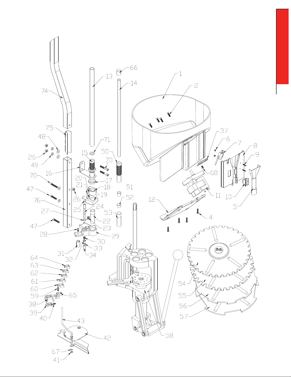
Lock-N-Load® AP™ Case Feeder
EXPLODED VIEW
ASSEMBLY
ASSEMBLY: CASE FEEDER
- 5 -
Page 6

Attaching the Square Tubing to the
3
Square Tubing
frame of the AP™ Press.
Place the ¼" Flat Washers (48) on the ¼-20 x 1 ¼" Socket
3
Head Cap Screw (SHCS) (47).
Place one SHCS through the Square Tubing (49) and thread
ASSEMBLY
into the Frame.
Repeat for the second Screw.
Tighten both screws down using a 3/16" Allen wrench.
Head Cap
Screw
¼-20 1 ¼" Cap Screw (Full Size)
Adding the Case Slide on to the
Sub-Plate
Assemble the Case Slide by placing the Spring (40) in the
4
relief of the Slide and hooking the relief of the Guide (39) onto
the end of the Spring. Slide the Guide forward and compress
the Spring until the Guide fits into the pocket. You may need
to hold the Guide and Spring into the Slide with your finger as
you slide the assembly back onto the “Sub-Plate.”
Inserting the Cam Wire into the
Assembly.
Raise the Ram to the top of the stroke.
5
Screw one #10-32 Hex Nut (41) onto the Cam Wire (43)
approximately 1" from the end.
Place one of the #10 Flat Washers (67) onto the Cam Wire.
From the bottom of the Sub-Plate, slide the non-threaded
end of the Cam Wire through the slot of the Sub-Plate and
through the Case Slide (38).
Place the threaded end of the Cam Wire through the hole of
the tab on the Main Bracket.
Place the other Flat Washer and Hex Nut onto the bottom of
the Cam Wire and tighten finger tight.
Lower the Ram.
4
5
Case Slide
Flat Washer
Spring
Guide
Sub-Plate
Cam Wire
- 6 -
Hex Nut
Flat Washer
ASSEMBLY: CASE FEEDER
Page 7

Case Escapement Bracket Assembly.
Put a ¼" Flat Washer on the ¼-20 X 1 ½" Cap Screw (70).
6
Place the Cap Screw through the Square Tubing and thread
the Hex Nut (26) the length of the nut.
¼-20 x 1 ½" Cap Screw (70)
(Full Size)
6
ASSEMBLY
Cap Screw
Hex Nut
Flat Washer
Slip the Pivot Block (29) over the Hex Nut (26) so
7
the Hex Nut (26) is in the slot on the back of the Case
Escapement Body.
Slip the Cam Wire (43) into the Cam Wire Support (31).
Tighten the Cap Screw while holding the Bracket level
with the top of the frame.
Feed Tube Mounting Bracket.
Slide the 1" Square Tube Connector (75) into the tubing (76)
8
with the open end of the V forward until the bottom hole lines
up with the uppermost hole in the tubing. Orient the Feed
Tube Mounting Bracket (16) as shown in the exploded view.
Place a ¼-20 x 1.50 SHCS (70) through the bottom hole, then
through the square tubing. Place a ¼ Flat Washer (48) and
¼ Lock Washer (49) over the screw, and lightly thread on a
¼-20 Hex Head Nut (26).
Slide the Case Feeder Stand 2-PC Upper tube (74) over the
Square Tube Connector (oriented as shown in the exploded
view) until the two holes line up. Place a ¼-20 SHCS through
the remaining hole in the Feed Tube Mounting Bracket and
through the square tubing. Place a ¼ Flat Washer and ¼ Lock
Washer over the screw, and thread on a ¼-20 Hex Head Nut.
Tighten both Hex Head Nuts until snug.
7
Cap Screw
Cam Wire
Cam Wire
8
Hex Nut
Pivot Block
Support
Cap Screw
¼-20 x 1 ½" Cap Screw (Full Size)
Feed Tube
Mounting
Bracket
ASSEMBLY: CASE FEEDER
- 7 -
Page 8

Installing the V-Block onto the
9
case slide.
Cap Screw
With the Ram at the bottom of the stroke (idle position), set the
9
V-Block onto the Case Slide (38).
ASSEMBLY
Refer to chart on page 13 for proper V-Block.
Place the #10-24 X 1/2 Cap Screw (59) through the hole of the
V-Block and screw it into the Case Slide. Before you tighten the
Cap Screw, push the V-Block back into the Case Slide and snug
the Cap Screw with your fingers.
The proper adjustments of the cam wire will be discussed later
on Change-Over: Case Feeder Page 14.
V-Block
Assembling the Feed Tube End
and Pivot.
If the maximum case diameter is larger than .43" you will
10
need to use the large Drop Tube (22). If it is smaller, you will
need the small Drop Tube (53). Place the correct one into the
Pivot Block (29).
Place the Torsion Spring (23) into the slot in the Pivot
11
Block (29), leaving the long leg on the top side. The Spring
will only fit one way.
10
Drop Tube
Pivot Block
11
Torsion Spring
- 8 -
ASSEMBLY: CASE FEEDER
Page 9

Assembling the Feed Tube End
and Pivot (con't).
12
ASSEMBLY
Set the Pivot (19) on top of the Pivot Block (29). Make sure
12
you line up the under cut in the bottom of the pivot with the
Torsion Spring (23). The leg of the Torsion Spring will fit into
the slot on the Pivot.
When this fits together, the Pivot should fit on top of the Pivot
Block. The Dowel Pin (21) in the Pivot will fit into the curved
slot on the Pivot Block (29).
Then insert the Shoulder Bolt (20) into the pivot and into the
pivot block and tighten with an Allen wrench.
Actuate the Pivot by hand to make sure it will rotate
13
smoothly and spring return back under the Feed Tube.
Shoulder
Bolt
Pivot
13
Pivot
For small rifle cases, place the Pivot Adapter Bushing (51 or 52)
14
into the hole of the Pivot Adapter.
14
Pivot Adapter
Bushing
ASSEMBLY: CASE FEEDER
- 9 -
Page 10

Place the Pivot Adapter (18) on top of the pivot for small
15
rifle cases.
Refer to page 13 for proper Pivot Adapter Bushing (51 or 52).
15
ASSEMBLY
Pivot Adapter
Placing the Feed Tube End on
the Assembly.
Select the Feed Tube End for your application.
16
Refer to page 13.
Screw one Lock Ring (17) on the Feed Tube End (15 or 50).
Place it through the hole on the Feed Tube Mounting Bracket
(16). Adjust the height of the Feed Tube End to have
approximately 1/16" below the bottom of the tube to the
case mouth. With some cases such as the 357 Mag, it may
be necessary to adjust the Feed Tube End to where the case
mouth sits up inside of the Feed Tube End approximately.
These are both starting points, and for your particular case,
it may need to be adjusted a little differently. (Long skinny
cases, which are shorter than 1.50" long, will not work with
the Pivot Adapter.) They may need to be supported at the
mouth of the case by the Feed Tube Ends. This will allow the
case to feed down
the Drop Tubes without falling over and causing double or
triple feeds.
Screw on the other Lock Ring (17).
16
Lock Ring
Feed Tube End
- 10 -
ASSEMBLY: CASE FEEDER
Page 11

Placing the Feed Tube end on
the Assembly (con't).
Select the proper Feed Tube and insert it in the top of the
17
Feed Tube End. If you select the Feed Tube End, you will have
to use the Plastic Feed Tube Small Bushing (66).
Refer to page 13.
(When feeding some cases, such as the 357 Mag, you may
notice that the base of the case will not fall into the hole
of the Pivot every time. The base will ride on the radius of
the pivot hole. This is correct because when the Push Rod
starts to rotate the Pivot, the case will fall into the hole.)
17
Feed Tube
Feed Tube End
ASSEMBLY
Push Rod
Feed Tube
Bushing
Small
Feed Tube
ASSEMBLY: CASE FEEDER
- 11 -
Page 12

Placing the Feed Bowl Hopper
on the Assembly
Select the Case Feed Plate for your application.
Refer to page 13.
18
ASSEMBLY
To install the Case Feed Plate, place Feed Plate over the
motor shaft and rotate until pawls on motor shaft engage the
two slots on the bottom of the Feed Plate.
Slide Case Feed Hopper on to the Square Tubing and the
19
Feed Tube.
18
Case Feed Plate
19
Feed Tube
Square Tubing
Maintenance of the Lock-N-Load® AP Case Feeder
As with all equipment, proper and routine maintenance will provide smooth operation and a longer life for your reloading
press and Case Feeder. At the end of each reloading session, wipe off all spilled powder, any dirt, etc., from the press.
Check all moving parts for dirt or spilled powder and remove with a clean rag.
- 12 -
ASSEMBLY: CASE FEEDER
Page 13

For cases smaller
than 0.43" use the
Small Feed Tube &
Small Feed Tube
Adapter
For cases larger
than 0.43" use the
Large Feed Tube &
Rubber O-Ring
Max.
Case Dia.
Setup / Changeover of the Lock-N-Load® Case Feeder
The Hornady Lock-N-Load Case Feeder is capable of feeding
both pistol and rifle cases. When changing cartridges, the
following components on the Case Feeder may need to be
changed or verified.
• Feed Plate
• Feed Tube
• Feed Tube End
• Pivot Adapter/Pivot Adapter Bushing
• Drop Tube
• V-Block
• Adjustment the Cam Wire
• Case Feed Door Adjustment
Small
Pistol
Plate
Small Pistol
(9mm, 40 S&W, etc.)
Large
Pistol
Plate
Small
Rifle
Plate
Large Pistol
(357 Mag, 44 Mag, etc.)
Small Rifle
(223 Rem, 22 Hornet, etc.)
Large Rifle
Large
Rifle
Plate
(243 Win, 45-70 Govt, etc.)
If the Feed Tube, Feed Tube End, Pivot Adaptor, Pivot Adaptor Bushing, or Drop Tube need to be changed; remove those items
and refer to Assembly: Case Feeder starting on Page 3.
Base Diameter
<0.43"
>0.43"
<0.43"
>0.43"
.27" – .30" 1
.37" – .39" 2
.35" – .38" 3
.42" – .47" 4
.41" – .44" 6
.27" – .30" 1
.37" – .39" 2
.35" – .38" 3
.42" – .47" 4
.41" – .44" 6
Refer to the chart below to determine the correct
components needed to operate the Lock-N-Load® Case
Feeder. Caliber specific sizing can be found on the
charts on page 16-19.
Changing Feed Plate
Remove the existing Feed Plate by pulling straight up on
the feed wheel to lift it off the motor drive shaft. To install
the new plate, place Feed Plate over the motor shaft and
rotate until pawls on motor shaft engage the two slots on
the bottom of the Feed Plate.
V-Block
Feed
Plate
S. Pistol #54
095310
L. Pistol #55
095312
S. Rifle #56
095314
L. Rifle #57
095316
Feed
Tub e
SM – #14 SM – #50 N/A 53
LG – #13
SM – #14 SM – #50
LG – #13
Feed Tub e
LG – #15
(INT – #73)
LG – #15
(INT – #73)
End
Pivot
N/A 22.46" – .58" 5
#18 & #51 or
#52
#18 22.46" – .58" 5
Adapter
Bushing
Drop Tube
53
CHANGE-OVER
Determining the size of the Clear Feed Tube
The base or rim diameter of the cartridge case determines
the size of the feed tube. In general, a case smaller than .43"
in diameter will use the Small Tube and Small Tube Adapter.
Cases larger than 0.43" will utilize the Large Feed Tube only.
Determining the use of the Pivot Adaptor
and/or Pivot Adapter Bushing (Rifle Cases Only)
The Pivot Adapter is used with rifle cases to help guide the taller
cases. You may also need to use the Pivot Adapter Bushing for
rifle cases with a smaller base diameter (i.e. 223 Rem.).
Determining the correct Feed Tube End
When changing the Feed Tube, the Feed Tube End will also
need to be changed. In general the Small Feed Tube End will
be used with the Small Feed Tube and the Large Feed Tube
End will be used with the Large Feed Tube. However, if you are
having trouble feeding certain cases (i.e. 40 S&W and 357 Mag)
through the Small Drop Tube, the Large Feed Tube can be used
with the Intermediate Drop Tube.
Determining the correct Drop Tube
In general, the Drop Tube helps guide the case onto the press
sub-plate. Again, a case smaller than .43" in diameter will use
the Small Drop Tube, and cases larger than 0.43" will utilize
the Large Drop Tube.
CHANGE-OVER: CASE FEEDER
- 13 -
Page 14

Replacing the V-Block
1
Refer to the chart and diagram on page 13 to determine the correct V-Block.
With the ram at the bottom of the stroke (idle position), set the V-Block onto
the Case Slide.
Place the #10-24 X 1/2 Cap Screw through the hole of the V-Block and screw
it into the Case Slide. Before you tighten the Cap Screw, push the V-Block
back into the Case Slide and snug the Cap Screw with your fingers.
1
V-Block
Place a case of the proper size into the shell plate and manually push the
2
Case Slide and V-Block into the case.
Loosen the Cap Screw and continue to push the Case Slide into the case.
Tighten the Cap Screw ) with a 3/16" Allen wrench.
Raise the ram until the shell plate rotates and place a case (of the proper
3
size) in front of the V-Block on the Sub-Plate. Lower the ram so the Case
Slide will advance the case into the shell plate.
Adjusting the Cam Wire
4
The Cam Wire determines the timing of the Case Feed Slide and must be
adjusted to allow the case to easily slide into the shell plate.
To adjust the Cam Wire, loosen both nuts so the wire can be moved either
up or down.
If the cases are not fully seating into the shell plate, raise the Cam Wire.
If the cases are hitting the shell plate when feeding, or the shell plate
cannot rotate, lower the Cam Wire.
Once the timing is correct, snug both nuts to the bracket and make sure
the Cam Wire is centered in the Slide. This can be adjusted manually by
rotating it a small amount around the threaded end. Tighten the nuts
CHANGE-OVER
to complete the timing process. This timing setting is adequate for all
cartridges and it should not be necessary to make future changes.
2
Cap Screw
3
4
Case Feed Door Adjustments
5
The Case Feed Door is used to prevent cases from falling down the Drop
Tube mouth first.
If loading pistol cases, the Case Feed Door should be opened completely
by loosening the Button Head Screw with a 1/8" Hex Wrench. Re-tighten
screw after completely opening the Case Feed Door.
If you are loading rifle cartridges, the length and weight of your cartridge
will determine how far the door must be opened. This may take some trial
and error.
Loosen the Button Head Cap Screw and slide the Case Feed Door
Adjustment so the opening is approximately ¾ the length of the case.
This is a preliminary setting. Place a hand-full of cases into the Case Feed
Bowl, and turn on the Case Feeder
Observe to see if the cases will fall base first. If they do not, readjust
the Case Feed Bowl Door Adjustment until they do without hanging up or
getting caught. Re-tighten the Button Head Cap Screw.
- 14 -
CHANGE-OVER: CASE FEEDER
Cam Wire
5
Page 15

Troubleshooting
Tips for Trouble-Free Operation of the Lock-N-Load® AP™ and Case Feeder
Problems Solutions
Powder dropping around case
• Correct bushing in place?
• Powder drop tube and measure adapter clean?
• Bushing installed deep counter sink side up?
No primer in case
Shell Plate will not advance or does not index on station
Cases do not feed into Dies
Gun powder is sticking in the powder measure, or
inconsistent charge weights
Case retainer spring won’t fall off the shell plate
or it is getting kinked
Cases are hitting the back corner of the shell plate when
feeding into the shell plate
Cases are not feeding into the shell plate far enough
Cases are tipping when going into the shell plate
• Primer slide properly adjusted?
• Correct primer punch installed?
• Primer slide spring in place?
• Correct primer slide installed?
• Primer body rotated counterclockwise when installed?
• Primer housing tube too tight?
• Primer not fully seated?
• Pawls correctly adjusted?
• Make sure you have the latest shell plate version with the groove on the bottom side.
• Die mouths beveled? (If not, return to manufacturer for repair.)
• Pawls timed correctly?
• Is the inside surface dry and clean?
• Try pouring a little powdered graphite through the powder measure for lubricant.
Rub the outside of the powder hopper with a dryer sheet to eliminate static.
• Is there a burr on the shell plate where the spring groove and the case location meet?
• Is there a burr on the sides of the slot on the sub-plate? (With a
case feeder, when you are setting up the timing, do not run the
case into the spring if the spring is up on the shell plate.)
Slow timing down or readjust V-Block location
Speed timing up or using the wrong V-Block
Readjust V-Block location
Cases are falling on top of the V-Block
Drop tube is tight against the AP™ frame; will not allow
changing of tubes
Cases are falling mouth first out of the bowl
Cases are getting caught in the open hole on the bowl
The shell plate is hitting the V-Block when it’s rotating
Readjust the bracket, square tubing
Readjust the bracket, square tubing
Close the door adjustment
Open the door adjustment
Lower the cam wire
Shell Plate Troubleshooting
Problems Solutions
Timing is severely out of adjustment
The Shell Plate does not rotate freely after mounting
*If you reach a point where you cannot get the press to work, please call our technical service staff at 800-338-3220 or write us by visiting: Hornady.com/contact_us.
The Index Pawls may have been damaged
• You may be trying to use the wrong version of shell plate. Your shell plate must have a groove
cut on the bottom side.
• Dirt or debris between the shell plate and the drive hub
• The Ball Detent bodies are not below flush on the underside of the Shell Plate.
• The Shell Plate is warped or damaged
TROUBLESHOOTING
TROUBLESHOOTING
- 15 -
Page 16

APPENDIX A
Rifle Dies & Reloading Essentials (Reference Chart)
Rifle
Cartridge
17 HORN ET .172 54 6118 I 046202 04 4101 — — — #3 / 3 905 43 #3 / 3 926 03 Sm R fl / 095 314 — * / 39 094 2 Small #1 / 3 9215 4
17 REM FIREBALL .172 54 6117 I 046200 04 4101 — — — #16 / 39 0556 #16 / 392616 Sm Rfl / 0 95 314 — * / 39 094 2 Small #1 / 3 9215 4
17 REM .172 546200 III 046201 044101 — — — #16 / 39 055 6 #16 / 392 616 Sm Rfl / 09 5314 — * / 39 094 2 Small #1 / 3 9215 4
17/222 .172 546202 IV — — — — — #16 / 390 556 #16 / 39 2616 Sm Rfl / 0 953 14 — * / 390 942 Small #1 / 3 92154
17/2 23 .172 546204 IV — — — — — #16 / 39 0556 #16 / 39 2616 Sm Rfl / 0 953 14 — * / 390 942 Small #1 / 39215 4
20 V T .204 546205 III 046206 044139 — — 046038 #16 / 39 055 6 #16 / 3 92616 Sm R fl / 095 314 — # 22 / 39 094 0 Small #14 / 392167
20 TACTICAL .204 546209 III 046208 044139 — — 046038 #16 / 390 556 #16 / 3 92616 Sm R fl / 09 5314 — # 22 / 39 094 0 Small #14 / 392 167
20 4 RUGER .204 546201 I 046590 0 44139 — — 046038 # 16 / 390 556 #16 / 3 92616 Sm R fl / 095 314 — # 22 / 39 094 0 Small #1 4 / 39216 7
22 HO RNET .224 546212 I 046213 0 44102 — — 046066 # 3 / 390543 # 3 / 392603 S m Rfl / 09 5314 — #1 / 390 943 Small #2 / 3 92155
22 K-HORNET .224 54 6214 IV — — — — 046066 #3 / 390 543 # 3 / 392 603 S m Rfl / 09 5314 — #1 / 390 943 Small # 2 / 392155
5.7x28 FN .224 546203 III 0 46212 044136 — — — # 37 / 39 057 7 — / — S m Rfl / 09 5314 — # 1 / 390 943 Small #2 / 392155
218 BEE .224 546206 IV — — — — 046066 #7 / 3 905 47 #7 / 3 926 07 S m Rfl / 09 5314 — # 1 / 390 943 Small #2 / 3 92155
221 REM FIREBALL .224 54 6210 III 0 46211 04410 2 — — 046040 # 16 / 390 556 #16 / 3 92616 Sm R fl / 095 314 — #1 / 3 909 43 Small #2 / 3 92155
222 REM .224 546224 I 046225 044102 — — 046040 # 16 / 390 556 #16 / 3 92616 Sm R fl / 095 314 — #1 / 3 909 43 Small #2 / 3 92155
223 REM .224 546228 I 046229 04 4102 — — 046040 # 16 / 390 556 #16 / 3 92616 Sm R fl / 095 314 095340 #1 / 39 094 3 Small #2 / 3 92155
22 3 REM MATCH .224 — — 544229 0 44102 — — 544227 #16 / 390 556 #16 / 392 616 Sm R fl / 09 5314 095340 #1 / 3 909 43 Small #2 / 3 92155
22 PPC .224 54 6216 IV — — — — 046053 #6 / 3 905 46 #6 / 392 606 Sm R fl / 09 5314 — #1 / 3 909 43 Small #2 / 3 92155
5.6 x50 MAG .224 546234 IV — — — — 046040 # 16 / 390 556 #16 / 3 92616 Sm R fl / 095 314 — #1 / 3 909 43 Small #2 / 3 92155
219 ZIPPER .224 546208 IV — — — — 046040 #2 / 3 905 42 #2 / 392 602 Lg R fl / 095 316 — #1 / 3 909 43 L arge #2 / 3 92155
22 5 WIN .224 546232 III 046233 044127 — — 046040 # 4 / 390544 # 4 / 392604 Lg R fl / 095 316 — #1 / 3 909 43 L arge #2 / 3 92155
224 WBY .224 546230 IV — — — — 046040 #17 / 3 905 57 — / — Lg R fl / 095 316 — #1 / 3 909 43 Large #2 / 3 92155
22/250 REM .224 546220 I 046221 04 4102 — — 046040 #1 / 3 905 41 #1 / 392 601 Lg R fl / 095 316 — #1 / 3 909 43 Large #2 / 3 92155
22 /250 ACKLE Y IMP .224 546 219 IV — — — — 046040 #1 / 3 905 41 #1 / 392 601 Lg R fl / 095 316 — #1 / 3 909 43 Large #2 / 3 92155
22 0 SWIFT .224 546222 I 046223 04 4127 — — 046054 #4 / 3 905 44 #4 / 3 92604 L g Rfl / 09 5316 — # 1 / 390 943 Large # 2 / 392 155
5.6x57 .224 546236 IV — — — — — # 1 / 390 541 #1 / 39 260 1 Lg R fl / 095 316 — #1 / 3909 43 L arge #2 / 3 9215 5
22 3 WIN SS MAG .224 546223 I 046558 044707 — — — # 35 / 39 0575 #35 / 392635 Lg R fl / 095 316 — #1 / 3 909 43 Large #2 / 3 92155
22/6MM .224 546249 III 046238 0 44127 — — 046054 #1 / 390 541 #1 / 3926 01 L g Rfl / 09 5316 — #1 / 390 943 Large #2 / 3 92155
22 SAV HP .227 546240 IV — — — — — #2 / 3 905 42 #2 / 390602 L g Rfl / 09 5316 — # 2 / 390 944 Large # 2 / 392 155
5.6x52R .227 546238 IV — — — — — #2 / 3 905 42 #2 / 390602 Lg R fl / 095 316 — #2 / 3 909 44 Large # 2 / 392 155
6MM/223 .243 546248 IV — — — — 046047 # 16 / 390 556 #16 / 3 92616 Sm R fl / 095 314 — #3 / 3 909 45 Small #3 / 3 92156
6MM T CU .243 546256 IV — — — — 046047 #16 / 390 556 #16 / 3 92616 Sm R fl / 095 314 — #3 / 3 909 45 Small #3 / 3 92156
6x47 REM .243 546258 IV — — — — 046047 # 16 / 390 556 #16 / 3 92616 Sm R fl / 095 314 — #3 / 3 909 45 Small #3 / 3 92156
6x47 L APUA MAT CH .243 — — — — — — — #1 / 3 905 41 #16 / 392 616 Sm R fl / 09 5314 — #3 / 390 945 Small # 3 / 392156
6MM PPC .243 546254 IV — — — — 046052 # 6 / 390 546 # 6 / 392 606 Sm R fl / 09 5314 — #3 / 390 945 Small #3 / 392156
6MM PPC MATCH .243 — — 544255 — — — 544253 # 6 / 390 546 # 6 / 392 606 S m Rfl / 09 5314 — #3 / 390 945 Small # 3 / 392156
6MM INT .243 546252 IV — — — — 046041 #1 / 3905 41 #1 / 3 926 01 L g Rfl / 09 5316 — # 3 / 390 945 Large #3 / 3 92156
6MM REM BR .243 546432 IV — — — — 046047 #1 / 3 90541 #1 / 392 601 Sm R fl / 09 5314 — #3 / 390 945 Small #3 / 392156
6MM REM BR MATCH .243 — — 5 44251 — — — 544259 #1 / 39 0541 #1 / 3 926 01 Sm R fl / 095 314 — # 3 / 390 945 Small # 3 / 392156
6MM HAGAR .243 546303 IV — — — — — #12 / 3 9055 2 #12 / 392 612 Sm R fl / 09 5314 — #3 / 3 909 45 Large # 3 / 392 156
APPENDIX A
6MM CREEDMOOR .243 546295 IV — — — — 046041 #1 / 3 905 41 #1 / 392 601 Lg R fl / 095 316 — #3 / 3 909 45 Large #3 / 3 92156
243 WIN .24 3 54624 4 I 04 6245 04 4103 — — 046041 #1 / 39 0541 #1 / 3 926 01 L g Rfl / 09 5316 — # 3 / 390945 Large #3 / 3 92156
244/6MM REM .243 546246 I 046247 044103 — — 046041 # 1 / 390541 #1 / 3 92601 L g Rfl / 09 5316 — # 3 / 390 945 Large #3 / 3 92156
6MM/284 .243 546250 IV — — — — 046041 #1 / 3 905 41 #1 / 3 92601 L g Rfl / 09 5316 — # 3 / 390 945 Large # 3 / 392156
240 WBY .243 546242 IV — — — — 046041 # 1 / 390541 #1 / 3 926 01 Lg R fl / 095 316 — #3 / 3 909 45 L arge #3 / 3 9215 6
243 WIN SS MAG .243 546225 I 046557 — — — — # 35 / 39 0575 #35 / 392635 Lg R fl / 095 316 — # 3 / 390 945 Large #3 / 3 92156
25/20 W IN .257 546264 IV — — — — — #7 / 390 547 # 7 / 392 607 S m Rfl / 09 5314 — # 4 / 390946 Small # 4 / 392157
25 6 WIN .257 546272 IV — — — — — # 6 / 390 546 # 6 / 392 606 Sm R fl / 09 5314 — #4 / 390 946 Large #4 / 3 92157
25/35 W IN .257 546266 IV — — — — — #2 / 3 905 42 #2 / 3 926 02 Lg R fl / 095 316 — #4 / 3 909 46 Large # 4 / 392 157
25 REM .257 546260 III 046276 044104 — — — #12 / 390 552 #12 / 392 612 Lg R fl / 095 316 — #4 / 3 909 46 Large #4 / 3 92157
25 0 SAV .257 546270 IV — — — — 046042 #1 / 39 0541 #1 / 3 926 01 Lg R fl / 09 5316 — #4 / 390 946 Large #4 / 3 92157
257 ROBERTS .257 546274 III 046275 044104 — — 046042 #1 / 3 905 41 #1 / 392 601 Lg R fl / 095 316 — #4 / 3 909 46 Large #4 / 3 92157
25 WIN SS MAG .257 546263 IV — — — — — # 35 / 390575 #35 / 392635 L g Rfl / 09 5316 — # 4 / 390 946 Large # 4 / 392157
25/06 REM .257 546262 I 046263 044104 — — 046042 #1 / 390 541 #1 / 3 92601 L g Rfl / 09 5316 — # 4 / 390 946 Large #4 / 3 92157
25/284 .257 546268 IV — — — — 046042 #1 / 3 905 41 #1 / 3 926 01 L g Rfl / 09 5316 — # 4 / 390 946 Large #4 / 3 92157
257 WBY .257 546276 III 046277 044104 — — 046042 # 5 / 390545 # 5 / 392 605 Lg R fl / 095 316 — # 4 / 390 946 Large #4 / 3 92157
6.5MMx47 MATCH .264 544650 — — — — — — # 1 / 390 541 — / — — / — — #5 / 3 909 47 Small #4 / 3 92157
6.5MM TCU .264 546296 IV — — — — 046048 #16 / 390 556 #16 / 392 616 Sm R fl / 09 5314 — #5 / 3 909 47 Small #4 / 3 92157
6.5 GRENDEL .264 546291 I 046598 04 4164 — — — #6 / 3 905 46 #6 / 3 926 06 Sm R fl / 095 314 — # 5 / 390 947 Large #4 / 3 92157
6.5 J AP .264 546290 III 046291 04410 6 — — 046043 # 34 / 39 0574 — / — Lg R fl / 095 316 — # 5 / 390 947 Large #4 / 3 92157
6.5 J DJ .264 — — — — — — 046043 # 4 / 390 544 #4 / 3 92604 L g Rfl / 09 5316 — # 5 / 390 947 Large #4 / 3 92157
6.5 MANN/SCH. .264 546292 IV — — — — 046043 # 20 / 39 056 0 — / — Lg R fl / 09 5316 — #5 / 3 909 47 Large #4 / 3 92157
6.5x55/SCAN. .264 546282 I 046283 04 4106 — — 046043 # 19 / 390 559 #19 / 3 92619 Lg R fl / 095 316 — # 5 / 390 947 Large #4 / 3 92157
260 REM .264 546269 III 0464 41 04410 6 — — 046043 #1 / 3905 41 #1 / 3 926 01 L g Rfl / 09 5316 — # 5 / 390 947 Large #4 / 3 92157
6.5 CREEDMOOR .264 546289 I 046596 04 4106 — — 046043 #1 / 39 0541 #1 / 3 926 01 L g Rfl / 09 5316 — # 5 / 390 947 Large #4 / 3 92157
6.5 C REEDMOOR MATCH .264 544655 — — — — — — #1 / 39 0541 #1 / 3 926 01 L g Rfl / 09 5316 — # 5 / 390 947 Large #4 / 3 92157
6.5x57 .264 546284 III 046285 0 44106 — — 046043 #1 / 3 90541 #1 / 392 601 Lg R fl / 095 316 — # 5 / 390 947 Large #4 / 3 92157
6.5/284 .264 546 301 III 046443 04 4106 — — 046043 #1 / 39 0541 #1 / 3 926 01 Lg R fl / 09 5316 — #5 / 390 947 Large #4 / 3 92157
6.5/06 .264 546280 III 046281 044123 — — 046043 #1 / 3 905 41 #1 / 3 926 01 Lg R fl / 09 5316 — #5 / 3 909 47 Large #4 / 3 92157
Bullet Diameter
(inches)
Die Set
Die Series
Full-Length
Size Die
Seating Die
Expander Die
Taper Crimp
Die Only
Neck Size Die
Shell Holder
# / Item No.
Shell Plate
# / Item No.
Case
Feeder Plate
Size / Item No.
Bullet
FeederDie
Trimmer Pilot
# / Item No.
Primer Punch
Bullet
Puller Collet
# / Item No.
- 16 - - 16 -
Page 17

APPENDIX A
Rifle Dies & Reloading Essentials (Reference Chart)
Rifle
Cartridge
6.5 R EM MAG .264 546294 IV — — — — 046043 # 5 / 390545 # 5 / 392 605 Lg Rfl / 0 95 316 — # 5 / 390 947 Large #4 / 3 92157
26 4 WIN MAG .264 546278 III 046279 044123 — — 046043 #5 / 3 905 45 #5 / 3 926 05 Lg R fl / 09 5316 — #5 / 3 909 47 Large #4 / 3 92157
6.5x68 .264 546286 III 046287 044123 — — 046043 # 30 / 39 0570 # 30 / 39 263 0 L g Rfl / 09 5316 — # 5 / 390 947 Large # 4 / 392 157
6.5 C ARC .268 546288 III 046289 044134 — — 046043 #21 / 390 561 — / — L g Rfl / 09 5316 — # 5 / 390 947 Large # 4 / 392 157
6.8MM REM SPC .277 546299 III 046711 044713 — — — #12 / 390 552 #12 / 3 92612 Lg R fl / 095 316 — # 6 / 390 948 Small # 5 / 392158
270 R EN .277 — — — — — — — #3 / 3 905 43 #3 / 3 926 03 Sm R fl / 095 314 — # 6 / 390 948 Small # 5 / 392158
270 W IN .277 546300 I 046301 04 4107 — — 046051 #1 / 390 541 #1 / 3926 01 L g Rfl / 09 5316 — #6 / 390 948 Large #5 / 3 92158
270 W IN SHORT M AG .277 546297 I 046450 044161 — — 046055 # 35 / 39 0575 #35 / 392635 L g Rfl / 09 5316 — # 6 / 390 948 Large #5 / 3 92158
270 WBY .277 546298 III 046299 04 4107 — — 046051 # 5 / 390545 # 5 / 392 605 Lg R fl / 095 316 — #6 / 3 909 48 Large # 5 / 392 158
7MM/2 23 INGRAM .284 54 6318 IV — — — — 046049 #16 / 3 905 56 #16 / 392 616 S m Rfl / 09 5314 — # 7 / 390949 Small # 6 / 392159
7MM TCU .284 546328 IV — — — — 046049 #16 / 3 905 56 # 16 / 392 616 Sm R fl / 09 5314 — #7 / 3 909 49 Small #6 / 3 92159
7x47 HELM .284 546306 IV — — — — 046049 #16 / 3 90556 # 16 / 392 616 Sm R fl / 09 5314 — #7 / 390 949 Large # 6 / 392 159
7MM REM BR .284 54 6324 IV — — — — 046049 #1 / 3905 41 #1 / 3 926 01 Sm R fl / 095 314 — # 7 / 390 949 Large # 6 / 392 159
7x3 0 WATERS .284 546304 IV — — — — 046049 # 2 / 390542 #2 / 3 92602 L g Rfl / 09 5316 — # 7 / 390 949 Large # 6 / 392159
7MM MERRILL .284 546322 IV — — — — 046044 #4 / 3 905 44 #4 / 392 604 Lg R fl / 095 316 — # 7 / 390 949 Large #6 / 3 92159
7MM/08 REM .284 546316 I 046317 04 4108 — — 046044 #1 / 39 0541 #1 / 3 926 01 Lg R fl / 09 5316 — #7 / 390 949 Large # 6 / 392 159
7x57-7MM MAUSER .284 546308 I 046309 04 4108 — — 046044 #1 / 3 905 41 #1 / 392 601 Lg R fl / 095 316 — # 7 / 390 949 Large #6 / 392159
7x57R .284 — — — — — — 046044 #13 / 3 90553 # 13 / 392 613 Lg R fl / 095 316 — #7 / 3 909 49 L arge #6 / 3 92159
28 4 WIN .284 546302 III 046303 044108 — — 046044 # 1 / 390 541 #1 / 39 260 1 Lg R fl / 095 316 — # 7 / 390 949 Large # 6 / 392159
280 REM/7MM EXP .284 546320 I 046321 0 44108 — — 046044 #1 / 3 905 41 #1 / 3 926 01 Lg R fl / 095 316 — #7 / 3 909 49 Large # 6 / 392 159
28 0 ACKLE Y IMP .284 546321 III 046304 04 4108 — — 046044 #1 / 3 905 41 #1 / 392 601 Lg R fl / 095 316 — # 7 / 390 949 Large #6 / 392159
7x65R .284 54 6314 III 046315 0 44133 — — 046044 #13 / 390 553 #13 / 3 92613 Lg R fl / 095 316 — # 7 / 390 949 Large # 6 / 392159
7x6 1 S&H .284 546310 IV — — — — 046044 # 35 / 39 0575 #35 / 392635 L g Rfl / 09 5316 — # 7 / 390 949 Large # 6 / 392159
7x64 .284 54 6312 III 046313 044108 — — 046044 # 1 / 390541 #1 / 3 92601 L g Rfl / 09 5316 — # 7 / 390 949 Large # 6 / 392159
7MM RE M SA ULTRA M AG .284 546309 III 046452 0 44108 — — 046056 #5 / 390 545 # 5 / 392 605 Lg R fl / 095 316 — #7 / 3 909 49 L arge #6 / 3 92159
7MM REM MAG .284 546326 I 046327 0 44108 — — 046044 #5 / 3 905 45 #5 / 392 605 Lg R fl / 095 316 — # 7 / 390 949 Large #6 / 392159
7MM W IN SHORT MAG .284 546327 I 04 6451 0 44108 — — 046056 # 35 / 39 0575 #35 / 392635 Lg R fl / 095 316 — # 7 / 390 949 Large #6 / 3 92159
7MM W BY .284 546330 III 046331 04 4108 — — 046044 #5 / 390 545 # 5 / 392 605 Lg R fl / 095 316 — #7 / 3 909 49 L arge #6 / 3 9215 9
7MM S TW .284 546440 IV — — — — 046044 # 5 / 390 545 # 5 / 392 605 Lg Rfl / 0 95 316 — # 7 / 390 949 Large # 6 / 392 159
7MM RE M ULTRA MA G .284 546307 III 046454 044133 — — 046056 #5 / 3 905 45 #5 / 392 605 Lg R fl / 095 316 — #7 / 3 909 49 L arge #6 / 3 92159
7.3 5 CARC .300 546332 IV — — — — — # 21 / 390 561 — / — L g Rfl / 09 5316 — # 8 / 390 950 Large # 7 / 392 160
30 M1 C ARB .308 546503 II 046504 04 4142 044505 — — # 22 / 39 0562 # 22 / 39262 2 Sm R fl / 095 314 — #9 / 3 909 51 Small #7 / 3 92160
30 REM .308 — — — — — — 046050 #12 / 3 90552 #12 / 392612 Lg R fl / 095 316 — # 9 / 390 951 Large #7 / 3 92160
300 AAC/WHISPER .308 546349 I 046459 044165 — — — #16 / 3 90556 #16 / 3 92616 Sm R fl / 095 314 — # 9 / 390 951 Small # 7 / 392160
30 HERRETT .308 546334 IV — — — — 046050 #2 / 3 905 42 #2 / 3 92602 L g Rfl / 09 5316 — # 9 / 390 951 Large #7 / 3 92160
30/30 WIN .308 546342 I 046343 0 44111 — — 046050 #2 / 3 905 42 #2 / 3 92602 L g Rfl / 09 5316 — # 9 / 390 951 Large #7 / 3 92160
30 -30 ACKLEY IMP .308 546345 IV — — — — 046050 # 2 / 390 542 #2 / 3 92602 L g Rfl / 09 5316 — # 9 / 390 951 Large #7 / 3 92160
30 3 SAV .308 546354 IV — — — — 046050 # 33 / 39 0573 — / — Lg R fl / 095 316 — # 9 / 390951 Large # 7 / 392 160
30 0 SAV .308 546348 III 046349 0 44111 — — 046050 #1 / 3905 41 #1 / 3 926 01 L g Rfl / 09 5316 — # 9 / 390 951 Large #7 / 3 92160
30 MERRILL .308 546338 IV — — — — 046050 # 4 / 390 544 # 4 / 392 604 Lg R fl / 095 316 — #9 / 3 909 51 L arge #7 / 3 9216 0
30 8 MARLIN EXP .308 546357 I 046358 044111 — — 046045 # 27 / 39 0567 #27 / 392627 Lg R fl / 095 316 — #9 / 3 909 51 L arge # 7 / 392160
7.5 S WIS S (7.5 X55 ) .308 546360 III 046361 04 4111 — — 046045 # 2 / 390 542 # 2 / 392 602 Lg R fl / 095 316 — #9 / 3 909 51 L arge #7 / 3 9216 0
7.5 SWISS K31 .308 546361 III 046362 0 44111 — — 046045 #2 / 390604 — / — L g Rfl / 09 5316 — #9 / 390 951 Large #7 / 3 92160
308 WIN .308 546358 I 046359 04 4111 — — 046045 #1 / 3 905 41 #1 / 3 926 01 L g Rfl / 09 5316 095345 #9 / 3 909 51 Large # 7 / 392 160
30 8 WIN MATCH .308 — — 544359 — — — 544357 # 1 / 390541 #1 / 3 926 01 Lg R fl / 095 316 095345 # 9 / 390 951 Large # 7 / 392 160
7.62 RUSS .308 546362 III 046363 044111 — — 046050 # 23 / 39 056 3 # 23 / 39 262 3 Lg R fl / 095 316 — # 9 / 390 951 Large #7 / 3 92160
30/40 KRAG .308 546344 IV — — — — 046045 # 11 / 39 0551 # 11 / 39 2611 L g Rfl / 09 5316 — # 9 / 390 951 Large #7 / 3 92160
30 TC .308 546335 I 046336 04 4111 — — 046045 #1 / 3 905 41 #1 / 3 926 01 Lg R fl / 095 316 — #9 / 3 909 51 Large # 7 / 392 160
30/06 .308 546340 I 046341 0 44112 — — 046045 #1 / 39 0541 #1 / 3 926 01 L g Rfl / 09 5316 — # 9 / 390951 Large #7 / 3 92160
30/06 AC KLEY IM P .308 546341 IV — — — — 046045 #1 / 39 0541 #1 / 3 926 01 Lg R fl / 09 5316 — #9 / 390 951 Large # 7 / 392 160
30 0 H&H .308 546346 IV — — — — 046045 #5 / 390 545 # 5 / 392 605 Lg R fl / 095 316 — #9 / 3 909 51 L arge #7 / 3 9216 0
300 OLYMPIC .308 546355 IV — — — — — #35 / 39 0575 #35 / 392635 Lg R fl / 095 316 — #9 / 3 909 51 L arge #7 / 3 9216 0
30 0 REM SA ULTR A MAG .308 546347 I 046455 04 4160 — — 046057 #5 / 3 905 45 #5 / 392 605 Lg R fl / 095 316 — # 9 / 390 951 Large #7 / 3 9216 0
30 8 NORMA MA G .308 546356 IV — — — — 046045 # 5 / 39054 5 # 5 / 392605 Lg R fl / 095 316 — #9 / 3 909 51 Large # 7 / 392 160
30 0 WIN SHOR T MAG .308 546369 I 046453 0 44160 — — 046057 # 35 / 39 0575 #35 / 392635 Lg R fl / 095 316 — #9 / 3 909 51 L arge #7 / 3 9216 0
30 0 RCM .308 546353 I 046592 0 44111 — — 046045 # 5 / 390545 #5 / 3 926 05 Lg R fl / 095 316 — #9 / 3 909 51 L arge # 7 / 392160
30 0 WIN MAG .308 546352 I 046353 0 44112 — — 046045 # 5 / 390545 # 5 / 392 605 Lg R fl / 095 316 — # 9 / 390 951 Large # 7 / 392 160
30 0 WBY .308 546350 I 046351 04 4112 — — 046045 #5 / 3 905 45 #5 / 3 926 05 L g Rfl / 09 5316 — # 9 / 390 951 Large #7 / 3 92160
30 0 REM ULTRA MAG .308 546365 I 046447 04 4159 — — 046057 #5 / 3 905 45 #5 / 392 605 Lg R fl / 095 316 — # 9 / 390 951 Large #7 / 3 92160
30/378 .308 546419 IV — — — — 046057 #14 / 3 905 54 #14 / 392 614 Lg R fl / 095 316 — #9 / 3 909 51 L arge #7 / 3 9216 0
307 WIN .308 — — — — — — 046045 # 33 / 39 057 3 — / — L g Rfl / 09 5316 — # 9 / 390 951 Large #7 / 3 92160
30 9 JDJ .308 — — — — — — 046045 #27 / 39 056 7 — / — Lg R fl / 09 5316 — #9 / 3 909 51 Large # 7 / 392 160
7.6 2x3 9 .308 546424 I 046425 04 4126 — — — #6 / 3 905 46 #6 / 3 926 06 Sm R fl / 095 314 — # 9 / 390 951 Large #7 / 3 92160
BLA NK CART 22-4 5 CAL — 54 4591 IV — — — — — — / — — / — — / — — — / — — — / —
32 /20 WI N .311 546364 III 046365 04 4113 — — — # 7 / 390547 # 7 / 392 607 Sm R fl / 095 314 — # 9 / 390 951 Small # 7 / 392 160
7.6 5 BEL G .3 12 546368 III 046369 04 4114 — — — # 24 / 390 564 — / — L g Rfl / 09 531 6 — #10 / 390 952 Large #7 / 3 92160
303 BRITISH .312 546366 I 046367 04 4114 — — — #11 / 3 90551 #11 / 392 611 Lg R fl / 095 316 — #10 / 390 952 Large #7 / 3 92160
7.7 J AP .312 546370 III 046371 044114 — — — #1 / 3 905 41 #1 / 3 926 01 L g Rfl / 09 5316 — #10 / 3 90952 Large # 7 / 392 160
Bullet Diameter
(inches)
Die Set
Die Series
Full-Length
Size Die
Seating Die
Expander Die
Taper Crimp
Die Only
Neck Size Die
Shell Holder
# / Item No.
Shell Plate
# / Item No.
Feeder Plate
Size / Item No.
Case
FeederDie
Bullet
Trimmer Pilot
# / Item No.
Primer Punch
Puller Collet
Bullet
# / Item No.
APPENDIX A
- 17 -
Page 18

APPENDIX A
Rifle Dies & Reloading Essentials (Reference Chart)
Rifle
Cartridge
32 /40 WIN .321 5463 74 IV — — — — — #2 / 3 905 42 #2 / 3 926 02 L g Rfl / 09 5316 — #11 / 3 90953 Large # 8 / 392 161
32 W IN SPL .321 546372 IV — — — — — # 2 / 390 542 # 2 / 392 602 Lg R fl / 095 316 — # 11 / 39 095 3 Large #8 / 3 92161
32 REM .321 — — — — — — — #12 / 3 90552 # 12 / 392 612 Lg R fl / 095 316 — #12 / 390 954 Large # 8 / 392 161
7.9 2x3 3 KU RZ .323 546375 III 046376 044137 — — — #1 / 39 0541 #1 / 3 926 01 Sm R fl / 095 314 — #11 / 3 909 53 L arge #8 / 3 92161
8MM M AUS .323 546382 I 046383 0 44116 — — — #1 / 3 905 41 #1 / 3 926 01 Lg R fl / 095 316 — #11 / 39 095 3 Large #8 / 3 92161
8x60S .323 546376 III 046377 044116 — — — #1 / 3 905 41 #1 / 3 926 01 Lg R fl / 095 316 — # 11 / 390 953 Large #8 / 3 92161
8MM/06 .323 546380 IV — — — — — # 1 / 390 541 #1 / 3926 01 Lg R fl / 09 5316 — #11 / 3909 53 Large # 8 / 392 161
8x5 0R LEBE L .323 546383 IV — — — — — #49 / 390605 — / — Lg R fl / 095 316 — #11 / 39 095 3 Large # 8 / 392161
32 5 WSM .323 546387 IV — — — — — # 35 / 39 0575 #35 / 392635 Lg R fl / 095 316 — # 11 / 39 095 3 Large #8 / 3 92161
8x68S .323 546378 IV — — — — — #30 / 39 0570 # 30 / 39 263 0 L g Rfl / 09 5316 — #11 / 3 909 53 L arge #8 / 3 92161
8MM REM MAG .323 546384 IV — — — — — #5 / 3 905 45 #5 / 3 926 05 L g Rfl / 09 5316 — #11 / 3 90953 Large # 8 / 392 161
8.15 X46R .324 546386 IV — — — — — # 2 / 390542 #2 / 3 92602 L g Rfl / 09 5316 — #11 / 3 909 53 Large #8 / 3 92161
8x56 HUNGARIAN-MANN .329 546385 IV — — — — — #47 / 390603 — / — Lg R fl / 09 5316 — #11 / 3909 53 L arge #8 / 3 92161
33 W IN .338 546388 IV — — — — 046058 #14 / 3 90554 # 14 / 392 614 Lg R fl / 095 316 — #13 / 390 955 Large # 9 / 392 162
33 8 FEDERAL .338 546397 III 046595 04 4131 — — 046058 #1 / 3 905 41 #1 / 3 926 01 Lg R fl / 095 316 — #13 / 390 955 Large #9 / 3 92162
33 8 MARLI N EXPRE SS .338 546359 I 046597 04 4131 — — 046058 #52 / 390607 #52 / 39 2652 Lg R fl / 095 316 — #13 / 390 955 Large # 9 / 392 162
33 8 NORMA MA G .338 — — — — — — 046058 # 43 / 39 058 3 — / — Lg R fl / 095 316 — #13 / 390 955 Large # 9 / 392162
338/06 .338 546395 IV — — — — 046058 #1 / 390 541 #1 / 3926 01 L g Rfl / 09 5316 — # 13 / 390 955 Large # 9 / 392162
33 8 RCM .338 546399 I 046594 04 4131 — — 046058 #5 / 3 905 45 #5 / 3 926 05 Lg R fl / 095 316 — #13 / 390 955 Large #9 / 3 92162
33 8 WIN MAG .338 546390 I 046391 04 4117 — — 046058 #5 / 390 545 # 5 / 392 605 Lg R fl / 095 316 — #13 / 390 955 Large # 9 / 392162
34 0 WBY .338 546392 IV — — — — 046058 #5 / 3 905 45 #5 / 392 605 Lg R fl / 095 316 — #13 / 390 955 Large # 9 / 392 162
33 8 ULTRA MA G .338 546389 III 046446 04 4117 — — 046058 #5 / 3 905 45 #5 / 392 605 Lg R fl / 095 316 — #13 / 390 955 Large # 9 / 392 162
33 8 LAPUA .338 546393 III 046593 0 4411 7 — — 046058 # 43 / 3905 83 — / — Lg R fl / 095 316 — #13 / 390 955 Large # 9 / 392 162
33 8/37 8 WBY .338 546391 IV — — — — 046058 # 14 / 390 554 #14 / 3 926 14 L g Rfl / 09 5316 — #13 / 3 909 55 Large #9 / 3 92162
34 8 WIN .348 546394 IV — — — — — # 25 / 39 0565 — / — L g Rfl / 09 5316 — # 14 / 390 956 Large # 9 / 392 162
35 REM .358 546398 III 046399 0 44130 — — — #2 6 / 390 566 — / — L g Rfl / 09 5316 — #15 / 3 909 57 L arge #9 / 3 9216 2
35 6 WIN .358 — — — — — — 046046 # 33 / 39 0573 — / — Lg R fl / 095 316 — #15 / 390 957 Large # 9 / 392 162
35 8 WIN .358 546408 IV — — — — 046046 #1 / 39 0541 #1 / 3 926 01 Lg R fl / 09 5316 — # 15 / 390 957 Large # 9 / 392 162
35 0 REM MAG .358 546402 IV — — — — — # 5 / 390 545 # 5 / 392 605 Lg R fl / 095 316 — #15 / 390 957 Large #9 / 3 92162
35 WHELEN .358 546400 III 046401 0 44119 — — 046046 #1 / 3905 41 #1 / 3 926 01 L g Rfl / 09 5316 — #15 / 3 90957 Large # 9 / 392 162
35 8 N MAG .358 546406 IV — — — — 046046 # 5 / 390 545 # 5 / 392 605 Lg R fl / 095 316 — #15 / 3 909 57 Large # 9 / 392 162
9.3x57 .366 546410 III 046411 04 4120 — — — #1 / 3905 41 #1 / 3 926 01 L g Rfl / 09 5316 — # 20 / 39 096 2 Large #9 / 3 92162
9.3x74R .366 546414 III 046 415 04 4120 — — — #13 / 3 905 53 # 13 / 392 613 Lg R fl / 095 316 — # 20 / 39 096 2 Large # 9 / 392 162
9.3x62 .366 546412 III 046 413 04 4120 — — — #1 / 3 905 41 #1 / 392 601 Lg R fl / 095 316 — # 20 / 39 096 2 Large # 9 / 392162
375 J DJ .375 — — — — — — — # 27 / 39 056 7 — / — Lg R fl / 095 316 — #16 / 390 958 Large #10 / 392 163
38 /55 WCF .375 546537 IV — — — — — #2 / 3 905 42 #2 / 3 926 02 L g Rfl / 09 5316 — # 16 / 390 958 Large #10 / 392163
375 W IN .375 546530 IV — — — — — #2 / 3 905 42 #2 / 392 602 Lg R fl / 095 316 — #16 / 390 958 Large #10 / 392163
376 STEYR .375 546417 IV — — — — — #15 / 3 905 55 — / — Lg R fl / 095 316 — #16 / 390 958 Large #10 / 392 163
375 H&H .375 546416 I 046417 044121 — — — # 5 / 390 545 #5 / 3 926 05 Lg R fl / 09 5316 — # 16 / 390 958 Large #10 / 3 9216 3
APPENDIX A
375 R UGER .375 546415 I 0 46418 04 4121 — — — # 5 / 390 545 # 5 / 392 605 Lg R fl / 095 316 — #16 / 390 958 Large #10 / 392163
375 R EM ULTRA M AG .375 546450 IV — — — — — #5 / 3 905 45 #5 / 3 926 05 Lg R fl / 095 316 — #16 / 390 958 Large #10 / 392163
378 W BY .375 546418 IV — — — — — #14 / 390 554 #14 / 3 92614 Lg R fl / 095 316 — #16 / 3 909 58 Large #10 / 392163
45 0/400 NE . 410 546421 IV — — — — — #54 / 390609 — / — Lg R fl / 09 5316 — # 17 / 390 959 Large # 11 / 39 2164
40 5 WIN .411 546425 II 046456 044162 044571 — — # 42 / 39 0582 — / — L g Rfl / 09 5316 — #17 / 3 909 59 Large # 11 / 39 2164
10.3x60 .415 546420 IV — — — — — # 25 / 39 0565 — / — L g Rfl / 09 5316 — #17 / 3 90959 Large # 11 / 39 2164
416 TAYLO R .416 546427 IV — — — — — #5 / 3 905 45 — / — Lg R fl / 095 316 — #17 / 390 959 Large # 11 / 39 2164
416 RIG BY .416 546428 IV — — — — — # 38 / 39 0578 — / — Lg R fl / 095 316 — #17 / 390 959 Large # 11 / 39 2164
416 RUG ER .416 546429 IV — — — — — #5 / 3 905 45 #5 / 3 926 05 L g Rfl / 09 5316 — #17 / 3 909 59 Large # 11 / 39 2164
416 REM MAG .416 546426 IV — — — — — #5 / 3 905 45 #5 / 3 926 05 L g Rfl / 09 5316 — #17 / 3 909 59 Large # 11 / 39 2164
416 WBY .416 546430 IV — — — — — #14 / 390 554 #14 / 392 614 Lg R fl / 095 316 — #17 / 390 959 Large # 11 / 39 2164
404 JEFFERY .423 546423 IV — — — — — #53 / 390608 — / — Lg R fl / 09 5316 — # 17 / 390 959 Large #12 / 392165
444 MARLIN .430 546551 II 046552 044149 044553 — — # 27 / 39 056 7 #27 / 392627 Lg R fl / 095 316 — #18 / 390 960 Large #12 / 392165
450 BUSHMASTER .452 546452 V 046422 044721 044550 044176 — # 1 / 390 541 #1 / 39 260 1 Lg R fl / 095 316 — #19 / 3 909 61 Large #13 / 392166
458 SOCOM .458 546464 III 046424 0 44190 — — — #1 / 390 541 #1 / 3926 01 L g Rfl / 09 5316 — #19 / 3 909 61 Small #13 / 392166
45 /70 GOV MT .458 546566 II 046567 0 44152 044568 — — #14 / 3 905 54 # 14 / 392 614 Lg R fl / 095 316 — #19 / 3 909 61 Large #13 / 392166
450 MARLIN .458 546553 II 046587 04 4152 044568 — — # 5 / 390545 # 5 / 392 605 Lg R fl / 095 316 — #19 / 3 909 61 L arge # 13 / 392166
45 0 NITRO E XPRESS .458 546433 IV — — — — — #54 / 390609 — / — N/A — #19 / 390 961 Large #13 / 392 166
45 8 WIN MAG .458 546569 II 046570 044153 044568 — — #5 / 390 545 # 5 / 392 605 Lg R fl / 095 316 — #19 / 390 961 Large #13 / 392 166
45 8 LOTT .458 546465 II 046457 044153 044572 — — # 5 / 390 545 # 5 / 392 605 Lg R fl / 095 316 — #19 / 390 961 Large #13 / 392 166
46 0 WBY .458 546422 IV — — — — — #14 / 390 554 #14 / 3 92614 Lg R fl / 095 316 — #19 / 3 909 61 Large #13 / 392166
470 NITRO E XPRESS .474 546434 IV — — — — — # 55 / 39 0610 — / — N /A — # 23 / 39 093 9 Large — / —
50/70 GOVT .510 546462 IV — — — — — — / — — / — Lg R fl / 095 316 — # 50 / 39 093 7 Large — / —
50 BEOWULF .500 — — — — — — — # 6 / 390 546 # 6 / 392 606 Lg R fl / 095 316 — # 50 / 39 093 7 Large — / —
50 ALASKAN .510 546586 IV — — — — — # 25 / 39 056 5 — / — Lg R fl / 09 5316 — # 50 / 39 093 7 Large — / —
50 0 NITRO E XPRESS .510 546435 IV — — — — — # 55 / 390610 — / — N/A — # 50 / 39 093 7 Large — / —
Bullet Diameter
(inches)
Die Set
Die Series
Full-Length
Size Die
Seating Die
Expander Die
Taper Crimp
Die Only
Neck Size Die
Shell Holder
# / Item No.
Shell Plate
# / Item No.
Feeder Plate
Size / Item No.
Case
FeederDie
Bullet
Trimmer Pilot
# / Item No.
Primer Punch
Puller Collet
Bullet
# / Item No.
- 18 - - 18 -
Page 19

APPENDIX A
Pistol Dies & Reloading Essentials (Reference Chart)
Pistol
Cartridge
22 RC FM-JE T .224 5 46218 IV — — — — — # 6 / 39054 6 # 6 / 392 606 Sm Ps tl / 095 310 N/A #1 / 3 909 43 Small
25 AU TO .251 — — — — — — — # 37 / 39 0577 — / — Sm Pst l / 095 310 N/A #4 / 3 909 46 Small
30 LUGER .308 546336 IV — — — — — # 8 / 390548 #8 / 3926 08 Sm Ps tl / 09 5310 N /A # 9 / 390 951 Small
30 MAUSER .309 — — — — — — — # 8 / 390 548 #8 / 3926 08 Sm Ps tl / 09 5310 N /A #9 / 3 909 51 Small
32 AU TO .311 546506 II 046507 0 44113 044508 — — # 22 / 39 056 2 #2 2 / 392 622 S m Pstl / 0 953 10 N /A #10 / 39 0952 Small
32 S &W LONG/ H&R/
327 FEDER AL
7.5 SWISS ORDE N .312 546504 IV — — — — — #48 / 390604 — / — Sm P stl / 0 9531 0 N/A #10 / 39 095 2 Small
8MM L EBEL REV .326 54 6510 IV — — — — — #48 / 390604 — / — Lg P stl / 0 95312 N/A # 11 / 39 095 3 Large
380 AUTO .355 54 6518 II 046519 044144 044517 — 04 4170 # 16 / 390 556 # 16 / 392 616 S m Pstl / 0 953 10 095330 # 15 / 390 957 Small
TAPER CRIMP 9MM/9x21 .355 5 46516 II 046516 044177 044517 044177 — #8 / 3 905 48 #8 / 3 926 08 — / — N /A #15 / 3909 57 Small
9MM LUGER/9x21 .355 546515 II 0 46516 044144 044517 — 04 4170 # 8 / 39054 8 # 8 / 392 608 Sm Ps tl / 09 5310 095330 #15 / 39 0957 Small
357 SIG .355 546575 II 046576 044144 044577 — — #10 / 39 055 0 #10 / 39 2610 Sm Ps tl / 09 5310 N /A #15 / 39 0957 Small
9x23 .355 546532 IV — — — — — #8 / 3 905 48 #8 / 3 926 08 Sm Ps tl / 09 5310 N /A #15 / 39 0957 Small
38 S&W .357 5 46521 IV — — — — — # 28 / 39 056 8 #2 8 / 392 628 Lg Ps tl / 09 5312 N /A #15 / 39 0957 Large
38 SU PER AUTO .357 546524 II 046525 044144 044526 — — #8 / 3 90548 #8 / 392 608 S m Pstl / 0 953 10 N /A #15 / 39 0957 Small
357 HERRETT .357 546396 IV — — — — — #2 / 39 054 2 #2 / 3926 02 L g Pstl / 0 95 312 N/A # 15 / 390 957 Large
357 B&D/44 .358 546404 IV — — — — — # 30 / 39 0570 # 30 / 39 263 0 Lg Ps tl / 09 5312 N /A #15 / 39 0957 Large
38 SP ECIAL .357 546527 II 046528 04 4145 044523 — — # 6 / 390546 # 6 / 39260 6 Lg P stl / 09 5312 095331 #15 / 3909 57 Small
357 MAGNUM .357 546527 II 046528 0 44145 044523 — — # 6 / 390 546 # 6 / 392 606 Lg P stl / 0 9531 2 0 95331 #15 / 39 0957 Small
357 REM MA X .357 546527 II 046528 0 44145 044523 — — #6 / 3 90546 #6 / 392 606 Lg P stl / 09 5312 095331 #15 / 39 095 7 Small
COWBOY 38-357-357 MAX .357 546528 III 046528 044591 044591 — — #8 / 3905 48 #8 / 3 926 08 Lg Ps tl / 095 312 N/A #15 / 39 095 7 Small
9x18 MAKAROV .364 5 46512 II 0 46513 0 44154 044 514 — — # 8 / 39054 8 # 8 / 392 608 Sm Ps tl / 09 5310 N/A #15 / 39 095 7 Small
40 S &W .400 546533 II 046534 044146 044535 — 0 44171 #10 / 39 055 0 #10 / 39 2610 Sm Ps tl / 09 5310 095332 #2 1 / 390 941 Small
TAPER CRIMP 4 0 S&W .400 546534 II 046534 04 4178 044535 0 44178 04 4171 #10 / 39 055 0 #10 / 392610 Lg Pst l / 095 312 N/A # 21 / 390 941 Small
10MM A UTO .400 546533 II 046534 044146 044535 — 0 44171 #10 / 3905 50 #10 / 3 92610 Lg Ps tl / 09 5312 095332 #2 1 / 390941 Large
TAPER CRIMP 10MM .400 546534 II 046534 044178 044535 04417 8 044171 #10 / 3 905 50 #10 / 3 92610 Lg Ps tl / 09 5312 N /A #21 / 3909 41 Large
38 /40 WIN .400 546536 IV — — — — — #9 / 3 905 49 #9 / 3 926 09 L g Pstl / 0 953 12 N /A # 21 / 390 941 Large
40 0 COR-BON .400 546538 IV — — — — — #45 / 390606 #45 / 392645 Lg Ps tl / 09 5312 N /A # 21 / 390 941 Large
41 AE .410 546539 II 046540 0 44147 044 541 — — # 29 / 39 0569 # 29 / 39262 9 Lg P stl / 09 5312 N/A #17 / 390 959 Small
41 REM M AG .410 546539 II 046540 044147 044541 — — # 29 / 39 0569 #29 / 39 262 9 Lg P stl / 09 5312 N /A #17 / 39 095 9 Large
COW BOY 44/4 0 WIN .429 546543 III 046460 044166 044593 — — #9 / 3 90549 #9 / 392 609 Lg P stl / 09 5312 N/A #18 / 3 909 60 Large
44 AU TO MAG .4 30 546545 IV — — — — — #1 / 3 905 41 #1 / 3 926 01 L g Pstl / 0 953 12 095333 # 18 / 390 960 L arge
44 RE M MAG .430 546548 II 046549 04 4148 044544 — — #3 0 / 390 570 #3 0 / 392 630 Lg P stl / 0 9531 2 N/A #18 / 39 096 0 Large
44 SP ECIAL .430 546548 II 046549 04 4148 044544 — — # 30 / 39057 0 #3 0 / 392 630 Lg P stl / 09 5312 095333 #18 / 39 096 0 Large
COW BOY 44 SPCL .430 546549 III 046549 04 4166 0 44166 — — #3 0 / 390 570 #3 0 / 392 630 Lg Ps tl / 09 5312 N /A #18 / 39 096 0 Large
44 5 SUPER MAG .430 — — — — — — — # 30 / 39 0570 # 30 / 39 263 0 Lg Ps tl / 09 5312 N /A #18 / 3909 60 Large
45 AU TO .451 546554 II 046555 0 44151 044556 — 0 44172 #45 / 390606 #45 / 392645 L g Pstl / 0 953 12 095334 # 19 / 390 961 Large
45 AU TO RIMME D .451 546554 II 046555 0 44151 044556 — 044172 # 31 / 390571 # 31 / 392 631 Lg P stl / 0 953 12 095334 #19 / 390 961 Large
45 WIN MAG .451 546554 II 046555 0 44151 044556 — 0 44172 #1 / 3 905 41 #1 / 3 926 01 Lg Ps tl / 095 312 095334 #19 / 390 961 Large
TAPER CRIMP 4 5 AUTO .451 546555 II 046555 044179 044556 0 44179 — #45 / 390606 #45 / 392645 L g Pstl / 0 95 312 095334 #19 / 39 0961 Large
COW BOY 45 COLT .452 546581 III 046583 04 4168 044594 — — # 32 / 39 0572 #32 / 392632 Lg Ps tl / 09 5312 095334 # 19 / 390 961 Large
45 C OLT .452 546582 II 046583 0 44151 044556 — — # 32 / 39 0572 #32 / 392632 Lg Ps tl / 09 5312 095334 # 19 / 390 961 Large
45 SCHOFIELD .452 546546 IV — — — — — # 41 / 390 581 — / — Lg P stl / 09 5312 095334 #19 / 39 0961 Large
45 4 CASULL .452 546584 V 046584 04 4151 044556 — 044588 # 32 / 39 0572 #32 / 392632 Lg Ps tl / 09 5312 095334 # 19 / 390 961 Small
46 0 S&W .452 546583 V 046720 044721 044719 — 044722 #46 / 390602 #4 6 / 392 646 Lg R fl / 09 5316 095334 #19 / 390 961 Large
45 5 WEBLE Y .455 — — — — — — — #51 / 390601 — / — L g Pstl / 0 953 12 N /A #19 / 3909 61 Large
48 0 RUGER/ 475 LINB .475 546547 V 046585 04 4158 044586 — 04 4174 #14 / 3905 54 #14 / 3 92614 Lg Ps tl / 09 5312 N /A # 23 / 39 093 9 Large
50 AC TION EX P .500 546580 II 046581 04 4155 044582 — — #4 0 / 390 640 — / — Lg R fl / 095 316 N/A #5 0 / 390 937 Large
50 0 S&W .500 546585 V 046699 044700 04 4701 — 044702 # 44 / 3905 84 #44 / 39 264 4 Lg R fl / 09 5316 N /A # 50 / 39 093 7 Large
500 LINEBAUGH .510 546587 IV — — — — — # 25 / 39056 5 — / — Lg R fl / 095 316 N/A # 50 / 39 093 7 Large
Bullet Diameter
(inches)
Die Set
Die Series
Full-Length
Size Die
Seating Die
Expander Die
Taper Crimp
Seater Die
Taper Crimp
Die Only
Shell Holder
# / Item No.
.3 11 546509 II 04 6510 044143 0 445 11 — — # 36 / 39 0576 # 36 / 39 263 6 S m Pstl / 0 953 10 N /A #10 / 3909 52 Small
Shell Plate
# / Item No.
Case
Feeder Plate
Size / Item No.
Bullet
FeederDie
Trimmer Pilot
# / Item No.
Primer Punch
APPENDIX A
- 19 -
Page 20

P.O. Box 1848, Grand Island, Nebraska 68802-1848
308-382-1390 • 800-338-3220 • Fax: 308-382-5761
780308-REV2 09/2014
www.hornady.com • Hornady.com/contact_us
 Loading...