

Page 1
®
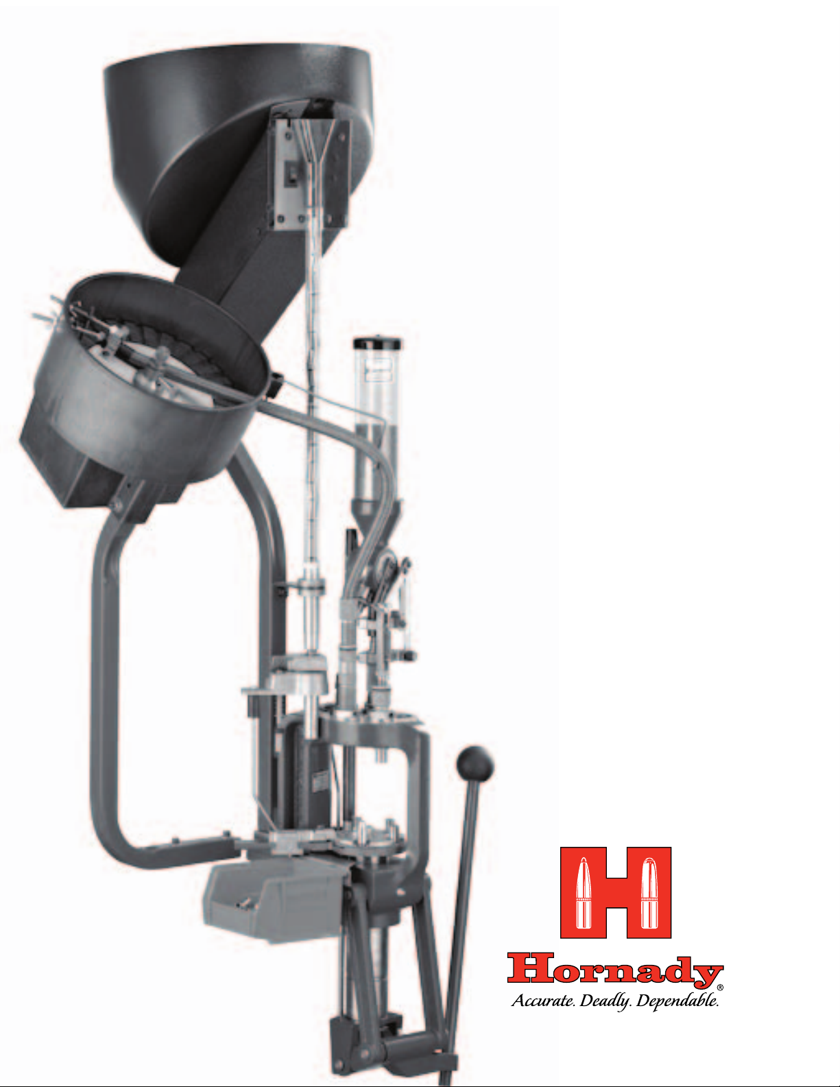
Lock-N-Load
AMMO
PLANT
•AutoProgressive(AP)
ReloadingPress
•PowderMeasure
&CaseActivated
PowderDrop
•CaseFeeder
•BulletFeeder
Page 2

TABLE OF CONTENTS
Lock-N-Load
®
Auto Progressive (AP) Reloading Press
Steps
Overview.....................................................................................................................5
Tools needed for assembly and set up ........................................................................5
1: Mounting the Lock-N-Load Auto Progressive .......................................................6
2: Determine which shell plate is required for your application ...............................7
2A: Installing the Shell Plate .....................................................................................8
2B: Removing the Shell Plate.....................................................................................9
3: Operation of your Lock-N-Load Auto Progressive Press ......................................10
4: Automatic Primer Feed Assembly ......................................................................11
4A: Installing the Primer Body .................................................................................11
4B: Installing the Primer Slide, Large or Small ........................................................ 11
4C: Installing the Primer Punch Assembly, Large or Small ......................................11
4D: Installing the Primer Tubes ...............................................................................11
4E: Installing the Primer Tube Housing ...................................................................11
4F: Primer Tube Support Installation .......................................................................12
5: Loading the Primer Tube ....................................................................................13
6: Changing Primer Tubes .....................................................................................14
7: Automatic Primer Feed Inspection .....................................................................15
8: Installing the Deluxe Powder Measure with Case Activated Powder Drop .......... 15
9: Lock-N-Load quick change bushing system ......................................................16
10: Die Mounting Instructions .................................................................................16
11: Preparing to Load ..............................................................................................17
12: Adjusting the Auto Advance Mechanism ...........................................................18
Maintenance of the Lock-N-Load AP .................................................................. 19
Tips for a Trouble-Free Operation .......................................................................20
Page
List of Illustrations
Figures
1. AP Mounting ........................................................................................................6
2. Installing Shell Plate ...........................................................................................8
3. Removing Shell Plate...........................................................................................9
4. Primer Feed System ...........................................................................................12
5. Filling the Priming System.................................................................................13
6. Lock-N-Load Powder Measure ...........................................................................15
7. Hornady Lock-N-Load System ............................................................................16
8. Pawl Adjustment ..............................................................................................18
Charts
1. Shell Plate Selection Chart ..................................................................................7
2. Trouble Free Operation .......................................................................................10
3. Bill of Materials ...................................................................................................3
4. Exploded View ......................................................................................................4
Lock-N-Load® AP Reloading Press
- 2 -
Page 3

BILL OF MATERIALS: LOCK-N-LOAD AP
ITEM
PRODUCTION
NO.
10 398359 1 PRIMER FOLLOWER
11 392338 1 SCREW SHCS 10-24 X 1/2
13 392455 1 BRACKET BOX CARTRIDGE
14 398319A 1 HOUSING BODY PRIMER TUBE
15 392218 1 PRIMER SLIDE LARGE ASSY.
15 392219 PRIMER SLIDE SMALL ASSY.
16 392336 1 SPRING PRIMER SLIDE
17 392363 1 SPRING CASE RETAINER
18 392210 1 CAM FEED PRIMER
19 39 2011 2 NUT NEX 10-32
20 190216 1 FRAME
21 392368 6 CLIP C C-50
22 480039 1 BOX CATCHER
23 392408 2 LINK LNLAP
24 398309T 1 SUB PLATE
26 398505 1 PRIMER SEATER PUNCH SMALL
26 398507 1 PRIMER SEATER PUNCH LARGE
PART NO.
1 398318 1 SUPPORT PRIMER TUBE
2 398356 1 TUBE PRIMER PICKUP LARGE
3 398355 1 TUBE PRIMER PICKUP SMALL
4 398358 1 TUBE PRIMER LARGE
5 398357 1 TUBE PRIMER SMALL
6 398322 1 HOUSING TUBE PRIMER
7 392220 1 SCREW BHCS 1/4-20 X 1/2
8 392202 1 BRACKET LNLAP
9 392342 1 SHCS SS 3/8-16 X 3/4
QTY. DESCRIPTION
ITEM
PRODUCTION
NO.
27 392467 1 SPRING COUNTER BALANCE
28 392345 1 3/8 FLAT WASHER SS
29 392355 1 DRIVE HUB
30 392356 1 DRIVE SHAFT
31 392231 2 SCREW BHSCS 8-32 X 3/8
32 392344A 2 PAWL
33 392423 2 SPRING PAWL
34 392306 2 DOWL PIN 1/8 X 1/2
35 392221 2 SCREW FHCS 1/4-28 X 3/8
36 290029 1 SPENT PRIMER TUBE
37 392359 1 RAM
38 398422 3 GREASE ZERK™
39 392343 1 TOGGLE
40 392340 1 PIN YOKE
41 392424 5 SPRING WASHER
42 392417 2 PIN LINK TOGGLE
43 390027 1 NUT JAM 5/8-18
44 390657 1 HANDLE
45 480003 1 KNOB
46 392357 1 YOKE
47 392358A 1 INDEX WHEEL
48 3900 81 2 CLIP E 1/2
49 392302 5 LOCK-N-LOAD BUSHING MALE
50 392303 5 LOCK-N-LOAD BUSHING O-RING
51 392365 1 SPENT PRIMER TUBE PLASTIC
52 392301 5
53 398715 1
PART NO
QTY. DESCRIPTION
LOCK-N-LOAD BUSHING FEMALE
WASHER
“We guarantee every one of our reloading tools and accessories for Life” No-Risk, Lifetime Warranty
Hornady reloading tools and accessories are warranted against material defects and workmanship for the life of the
products. Parts which by nature of their function are subject to normal wear such as springs, pins, bearings, etc…
and parts which have been altered, abused, or neglected are excluded from the warranty.
If the product is deemed defective by either workmanship or material, the reloading tool or accessory will either be
repaired, reconditioned or replaced at Hornady Manufacturing Company’s option. If it breaks, we’ll repair it or replace
it at no charge.
To return a product, call toll free (800) 338-3220 and ask for Customer Service. They will provide instructions for return
if the problem can’t be solved over the phone. Prices and or specifications are subject to change without notice. For the
best prices on any of our products, contact your nearest Hornady dealer.
Hornady Manufacturing Company cannot assume liability for damage which may result from use of the products or
information given herein, since Hornady had no control over the manner in which its products or components are used
during reloading.
- 3 -
Lock-N-Load® AP Reloading Press
Page 4
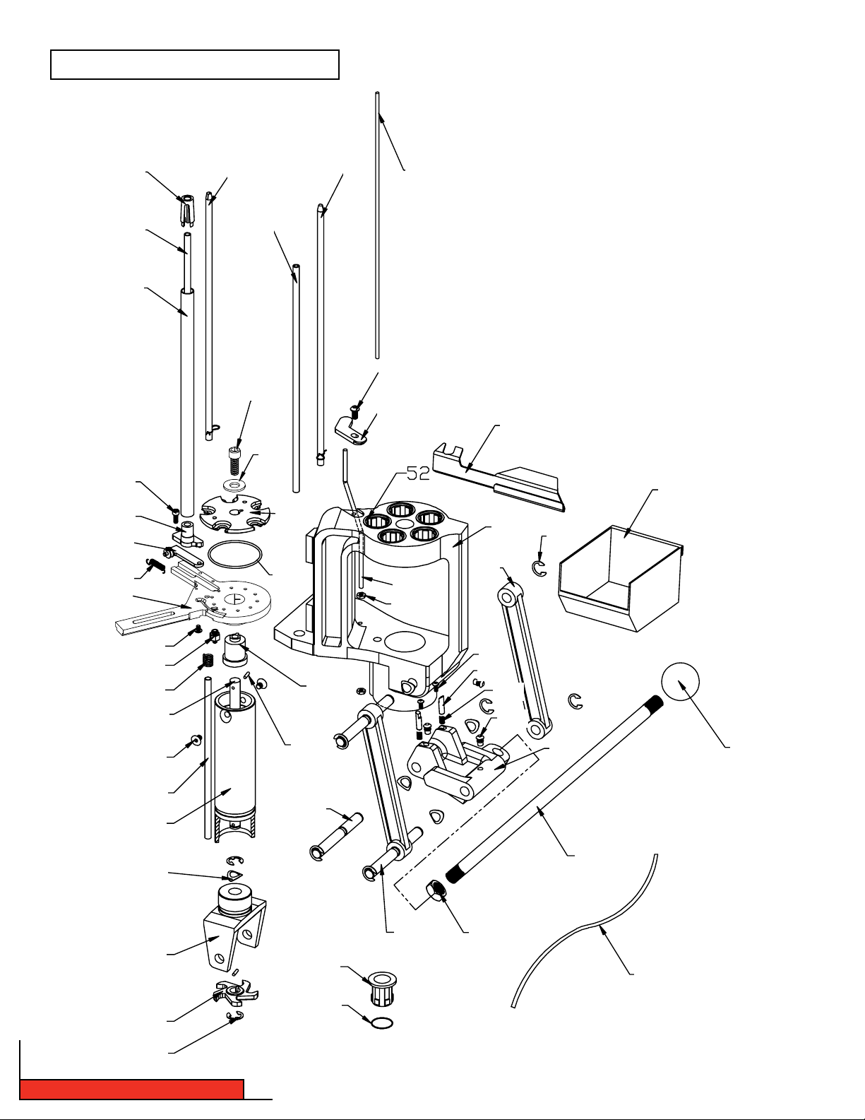
EXPLODED VIEW: LOCK-N-LOAD AP
11
14
15
16
24
1
4
2
5
3
10
6
7
9
8
13
28
22
12
17
20
23
21
18
19
25
26
27
30
35
36
37
41
46
47
48
34
40
29
49
50
31
32
42 43
33
38
39
45
44
51
Lock-N-Load® AP Reloading Press
- 4 -
- 4 -
Page 5
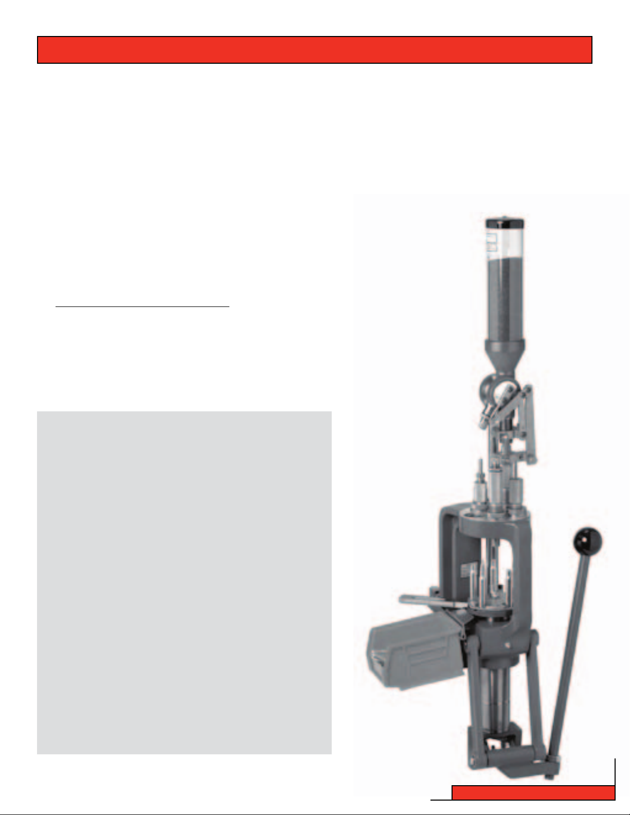
OVERVIEW OF LOCK-N-LOAD® AUTO PROGRESSIVE (AP) RELOADING PRESS
Your new Lock-N-Load Auto Progressive (AP) reloading press has been packaged to insure minimal vibration and damage
during transportation.
Remove all the parts from the packing box and spread them out over a large flat surface. Refer to the parts list on pages
19 and 20 and check to make sure all necessary parts are identified.
The manual provides step-by-step instructions and suggestions that make set-up and operation easy and understandable.
If at any time during operation you feel like you are forcing the press, stop and identify the
problem. Do not force anything, or damage could occur. Powders and Primers are explosive
if handled carelessly! Always work slowly and carefully without distractions and wear
eye protection. Try to avoid touching primers with oily fingers. The oil on your fingers may
contaminate the primers and cause them to misfire.
Tools needed for assembly and set-up:
•7⁄ 16" End Wrench
•(2) 1 ⁄ 2" End Wrenches
•15 ⁄16" End Wrench
•3 ⁄ 32" Hex Wrench (included)
•5⁄32" Hex Wrench
•Needle Nose Pliers
•Electric Drill
•5/16" Hex Wrench
•1/8" Hex Wrench (included)
Hand loading is very safe, but before reloading any case
please read the following warnings.
•Primers may explode if subjected to impact or heat.
•Keep away from the opening end of the Primer Tube at
all times.
•Variations may occur with different brands and condition
of cartridge cases, which can cause inconsistent primer
and bullet seating. Sort and inspect all of your cases
before reloading.
•Verify your powder charges at frequent intervals to
insure consistency.
•Careless or improper hand loading techniques can result
in serious personal injury. Make sure there are no
distractions while you are reloading.
•Before operating this press, be sure you have read and
understand all the instructions contained in this manual,
and that you understand the principals of hand loading.
- 5 -
Lock-N-Load® AP Reloading Press
Page 6
INSTRUCTIONS FOR LOCK-N-LOAD® AUTO PROGRESSIVE (AP) RELOADING PRESS
Step 1: Mounting the Lock-N-Load® Auto Progressive
•Your work area should be well lit and have plenty of room for your reloading accessories. Your Hornady Lock-N-Load
AP should be mounted securely 2 1/4" from the edge of a solid level bench. (Check for obstructions on or below
the bench before you drill any holes.)
•Mount the press using (2) 5/16" bolts that are long enough to secure the press to the bench with plenty of
clearance for the nuts. (Due to variation of benches, these bolts are not provided.) We also recommend using
5/16" flat washers top and bottom, in addition to lock washers on the bottom side.
•Insert and secure the right-hand mounting bolt first. Next, insert and secure the left-hand bolt, placing the
cartridge catcher bracket (13) underneath the bolt head and washer before tightening.
•Thread the press Handle (44) into the Toggle (39) at the bottom of the press and tighten the Jam Nut (43)
using a 15/16" wrench.
Figure 1: AP Mounting
5/16 BOLT
5/16 FLAT WASHER
CARTRIDGE CATCHER BRACKET (13)
JAM NUT (43)
Lock-N-Load® AP Reloading Press
TOGGLE (39)
- 6 -
Page 7

SHELL PLATES
Step 2: Determine which shell plate is required for your application
See Chart 1 below to help with this selection.
* Hornady shell plates that are sold in the
plastic boxes are the only ones that will
fit the AP Press with EZject
™
System.
These shell plates (which are sold
separately) are manufactured with a
groove on the bottom side.
Shell Plate/
Cartridge Dia
17 RE M .17 2 16 392616 390556
17 RE M FIREB ALL .172 16 392616 390556
17-222 .1 72 16 392616 390556
17-22 3 .17 2 16 392616 390556
20 TACTICAL .2 04 16 392616 390556
20 4 RUGER .204 16 392616 390556
218 BE E .222-.224 7 392607 39 0547
22 RCFM-JET .222-.223 6 392606 39 0546
219 ZIPPER .224 2 392602 390542
22 HO RNET .2 24 3 39260 3 390543
22 K- HORNE T .224 3 392603 390543
22 PP C .2 24 6 392606 39054 6
22 0 SWIF T .224 4 392604 390544
22 0 VT .224 16 392616 390556
221 R EM FIR EBAL .224 16 392616 390556
222 REM . 224 16 392616 390556
22 2 REM MA G .224 16 392616 390556
22- 250 AC K IMP .224 1 392601 3 90541
22-250 REM .2 24 1 392601 3 90541
22 3 REM . 224 16 392616 390556
22 3 WSSM .224 35 392635 390575
22 4 WBY MAG .224 17 N/A 390557
22 5 WIN .224 4 392604 390544
5.6 X50 M AG .224 16 392616 390556
5.6x57 .224 1 392601 390 541
5.7 J OHNSON S PITF IRE .224 22 392622 390562
5.7 X28 MM FN .224 37 N/A 390577
22 S AV HP .227 2 392602 39 0542
5.6X52R .2 27 2 392602 3 90542
24 0 WBY MA G .243 1 392601 3 90541
24 3 WIN .243 1 392601 39 0541
24 3 WSSM .243 35 392635 390575
244/6MM REM .243 1 392601 39 0541
6MM I NT .243 1 392601 3 90541
6MM P PC .243 6 392606 390546
6MM R EM BR .243 1 392601 3 90541
6MM T CU .243 16 392616 390556
6MM-22 3 .243 16 392616 390556
6MM-28 4 .243 1 392601 3 90541
6X4 7 REM .243 16 392616 390556
25 AU TO .251 37 N/A 390577
25 W SSM .257 35 392635 390575
25 0 SAV .257 1 392601 3 90541
25-06 REM .257 1 392601 3905 41
25 -20 WIN .257 7 392607 390547
25-2 84 .257 1 392601 390 541
25-35 WIN .257 2 392602 39 0542
25 6 WIN MA G .257 6 392606 390546
25 7 RBTS .257 1 392601 3 90541
25 7 WBY MA G .257 5 392605 390545
25 RE M .257 12 392612 39 0552
26 0 REM .26 4 1 392601 3 90541
26 4 WIN MA G .264 5 392605 390545
6.5 CREEDMOOR .264 1 392601 39 0541
6.5 GRENDEL .264 6 392606 390546
6.5 J AP .264 34 N/A 390574
6.5 JDJ .264 4 392604 3905 44
6.5 M ANN .264 20 N/A 390560
6.5 R EM MAG .264 5 392605 390545
6.5-06 .264 1 392601 390 541
6.5-2 84 .264 1 392601 3 90541
6.5MM TCU .264 16 392616 390556
6.5X55 SCAN (SWEDISH) .264 19 392619 390559
6.5X57 .264 1 392601 39 0541
6.5X68 .264 30 392630 390570
6.5 C ARC .264-.267 21 N/A 390561
27 0 REN .277 3 392603 390543
27 0 WBY MAG .277 5 392605 390545
27 0 WIN .277 1 392601 3 90541
27 0 WSSM .277 35 392635 39 0575
6.8 R EM SPC .277 12 392612 390552
28 0 REM ACK I MP .284 1 392601 3 90541
28 0 REM/ 7MM E XP .284 1 392601 3 90541
28 4 WIN .284 1 392601 390 541
7MM MERRILL .284 4 392604 39 0544
7MM R EM BR .284 1 392601 39 0541
7MM R EM MAG .28 4 5 392605 3905 45
7MM R EM ULTR A MAG
7MM R SAUM .284 5 392605 3905 45
Shell
Holde r #
.284 5 3
Shell
Plate
Item#
Shell
Holder
Item #
92605 390545
Shell Plate/
Cartridge Dia
7MM S TW .284 5 392605 390545
7MM T CU .284 16 392616 390556
7MM W BY MAG .284 5 392605 3 90545
7MM W SM .284 35 392635 390575
7MM-08 .284 1 392601 39 0541
7MM -223 IN GRAM .284 16 392616 390556
7X 30 WATE RS .284 2 392602 390542
7X47 HELM .284 16 392616 390556
7X 57 (7MM M AUSE R) .284 1 392601 39 0541
7X57R .284 13 392613 390553
7X 61 S&H .284 35 392635 390575
7X64 .284 1 392601 39 0541
7X65R .284 13 392613 390553
7.3 5 CAR C .298 21 N/A 390561
30 R EM .308 12 392612 390552
30 HE RRE TT .308 2 392602 390542
30 L UGER .308 8 392608 3 90548
30 M1 C ARBIN E .308 22 392622 390562
300 H&H .308 5 392605 39 0545
300 OLYMPIC (OSSM) .308 35 392635 390575
300 RCM .308 5 392605 390545
30 0 REM ULT RA MAG .308 5 392605 3905 45
300 RSAUM .308 5 392605 390545
300 SAV .308 1 392601 390 541
30 0 WBY MA G .308 5 392605 3905 45
30 0 WIN MA G .308 5 392605 390545
300 WSM .308 35 392635 390575
30-06 SPRINGFIELD .308 1 392601 390 541
30 -30 AC K IMP .3 08 2 392602 3 90542
30-30 WIN .308 2 3926 02 390542
30 -378 W BY MAG .308 14 392614 390554
30 -40 K RAG .308 11 392611 3905 51
30 7 WIN .308 33 N/A 390573
30 8 MARL IN EX PRESS .308 27 N/A 390567
30 8 NORMA M AG .308 5 392605 390545
30 8 WIN .308 1 392601 3 90541
309 JDJ .3 08 27 N/A 390567
30MM MERRILL .308 4 392604 39 0544
30TC .308 1 3 92601 39 0541
7.5 S WIS S .308 2 392602 390542
7.6 2X3 9 .3 08-.310 6 392606 39 0546
7.6 2 RUS SIAN .308-.312 23 392623 390563
30 MAUSER .309 8 392608 3905 48
30 3 SAV .3 11 33 N/A 390573
32 AU TO .311-.312 22 392622 390562
30 3 BRIT ISH .312 11 392611 390551
32 H &R MAG .312 36 392636 3 90576
32 S &W .312 36 392636 390576
32 S &W LONG .312 36 692636 3 90576
32-20 WIN .312 7 392607 39 0547
327 FEDERAL .312 36 392636 3 90576
7.6 5 BEL GIAN .312 24 N/A 390564
7.7 JA P .312 1 392601 3 90541
8.15 X46 R .312-.330 2 392602 3905 42
7.5 SW ISS ORD EN . 315 48 N/A 390604
32 RE M .321 12 392612 390552
32 W IN SPL .321 2 392602 390542
32-40 WIN . 321 2 392602 3 90542
32 5 WSM .323 35 392635 39 0575
7.9 2X 33MM KUR Z .323 1 392601 39 0541
8MM R EM MAG .323 5 392605 390545
8MM-06 .323 1 392601 390 541
8X 50 LEB EL .323 49 N/A 390605
8X 57 (8M M MAUSE R) .323 1 392601 390 541
8X6 0 S .323 1 392601 390 541
8X6 8 S .323 30 392630 390570
8MM LEBEL (HANDGUN) .326 48 N/A 390604
8X56R HUNG-MA NN .329 47 N/A 390603
33 W IN .338 14 392614 39 0554
338 FEDERAL .338 1 392601 390 541
33 8 LAP UA .338 43 N/A 390583
33 8 MARL IN EX PRESS .338 52 N/A 390607
33 8 NORM A MAG .338 43 N/A 390583
33 8 RCM .338 5 392605 390545
33 8 REM ULT RA MAG .338 5 392605 3905 45
33 8 WIN MA G .338 5 392605 390545
338-06 .338 1 392601 3 90541
338-378 WBY MAG
Shell
Holde r #
.338 14 3
Shell
Plate
Item#
Shell
Holder
Item #
92614 39055 4
- 7 -
Shell Plate/
Cartridge Dia
34 0 WBY MA G .338 5 392605 3905 45
34 8 WIN .348 25 N/A 390565
35 7 SIG .355 10 392610 390550
38 0 AUTO .355 16 392616 390556
9MM LUGER .355 8 392608 390548
9X 21 .355 8 392608 3905 48
9X 23 WIN .355 8 392608 390548
38 AU TO .355-.357 8 392608 39054 8
38 SU PER AU TO .357 8 392608 390548
35 7 MAGNU M .357 6 392606 3905 46
35 7 REM MA X .357 6 392606 390546
357-44 B&D .357 30 392630 390570
38 SP ECIA L .357 6 392606 390546
35 RE M .357-.358 26 N/A 390566
35 7 HERRE TT .357-.358 2 392602 390542
35 W HELEN .358 1 392601 3 90541
35 0 REM MA G .358 5 392605 39 0545
35 6 WIN .358 33 N/A 390573
35 8 NORMA M AG .358 5 392605 390545
35 8 WIN .358 1 392601 3 90541
38 S&W .359 28 392628 390568
9X18 MAKAROV .365 8 392608 39054 8
9.3X57 .366 1 392601 3 90541
9.3X62 .366 1 392601 3 90541
9.3X74R .366 13 392613 390553
375 H&H .375 5 392605 390545
37 5 JDJ .375 27 N/A 390567
37 5 REM ULT RA MAG .375 5 392605 390545
37 5 RUGER .375 5 392605 390545
37 5 WIN .375 2 392602 390542
37 6 STEY R .375 15 N /A 390555
37 8 WBY MAG . 375 14 392614 39055 4
38 -55 WI N .375 2 392602 3905 42
10MM A UTO .400 10 392610 390550
38 -40 W IN .400 9 392609 390549
40 S &W .400 10 392610 390550
400 COR-BON .400 1 392601 390 541
41 REM M AG .410 29 392629 390569
40 5 WIN .4 11 42 N /A 3905 82
10.3X60 .415 25 N/A 390565
416 RE M MAG .416 5 392605 390545
416 RIG BY . 416 38 N/A 390578
416 RU GER . 416 5 392605 3905 45
416 WB Y MAG .416 14 392614 390554
40 4 JEFF ERY * .42 3 53 N /A 390608
44 -40 W IN .427 9 392609 390549
44 A UTO MA G .430 1 392601 39 0541
44 R EM MAG .430 30 392630 3 90570
44 S PECIA L .430 30 3 92630 390570
444 MARLIN .4 30 27 N/A 390567
44 5 SUPER M AG .4 30 30 392630 390570
45 AU TO .451 45 392645 390606
45 AU TO RIM MED .451 31 392631 390571
45 W IN MAG .451 45 3 92645 390606
45 C OLT .452 32 392632 390572
45 SC HOFIE LD .452 41 N/A 390 581
45 4 CASU LL .452 32 392632 390572
460 S&W .452 46 3 92646 390602
455 WEBLEY .455-.456 51 N/A 390601
45 /70 GO V .458 14 392614 39 0554
450 BUSHMASTER .458 1 392601 39 0541
45 0 MARL IN .458 5 392605 390545
45 0 NITR O EXPR ESS* .458 54 N/A 390609
45 0-4 00 NE 3" .458 25 N/A 390565
45 8 LOT T .458 5 392605 390545
458 SOCOM .458 1 392601 3 90541
45 8 WIN .458 5 392605 3905 45
46 0 WBY MA G .458 14 392614 39055 4
470 N ITRO E XPRE SS* . 474 55 N/A 390610
475 LINEBAUGH .475 14 392614 390554
48 0 RUGER .475 14 392614 390554
50 A &E .500 40 39264 0 390580
50 BEOWULF .500 6 3 92606 390546
500 S&W .500 44 392644 39058 4
50 A LASK AN .510- .512 25 N/A 390565
500 LINEBAUGH .510 25 N/A 390565
50 0 NITR O EXPR ESS* . 510 55 N/A 390610
Shell
Holde r #
Shell
Plate
Item#
Shell
Holder
Item #
Lock-N-Load® AP Reloading Press
Page 8
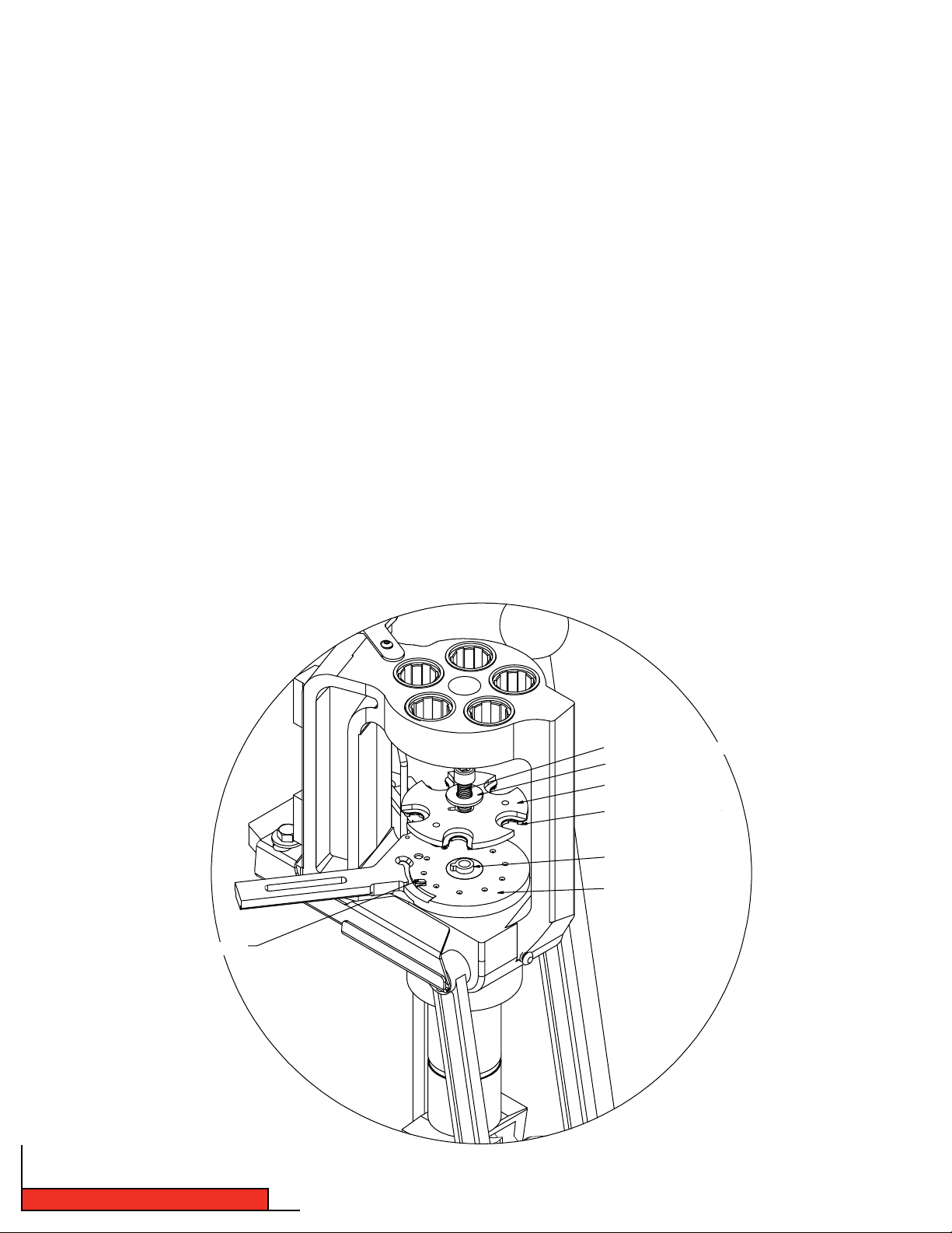
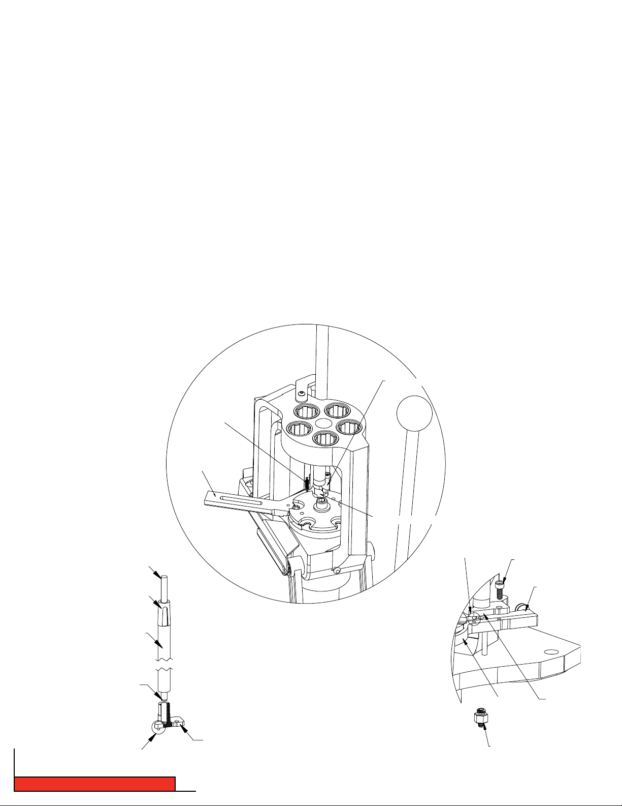
2A: Installing the Shell Plate
•Raise the Ram approximately 2" and place block under Sub Plate (24). This disengages the Index Pawls (32),
and allows for free rotation of the Shell plate.
•Put a small amount of general-purpose grease on the Shell Plate Ball Detents located on bottom side of Shell
Plate (12), and on the top surface of the Sub-Plate (24).
•Align the Shell Plate* with the keyed Drive Hub (29).
•Place the 3/8" Shell Plate Retainer Bolt (9) thru the 3/8" Flat Washer (28), (large end up) and thread the bolt
into the Drive Hub (29).
•Tighten the bolt (9) using a 5/16" Allen wrench, only tight enough to prevent it from coming loose.
•Stretch the Case Retainer Spring (17) over the top of the Shell Plate (12).
•Remove Block from under Sub-Plate (24) and make sure it is in the Retainer Spring Groove (17A).
•While cycling the Press, push the Case Retainer Spring (17) into the relieved area on the Sub-Plate (24).
You will have to cycle the press a couple of stations to receive these results.
•Check to make sure the Drive Pawls (32) are properly timed by cycling the press with the handle. A properly
timed press will rotate the Shell Plate so the Ball Detents on the Shell Plate always engage the recesses in
the Sub Plate.
EZject
Figure 2: Installing Shell Plate
SHELL PLATE RETAINER BOLT (9)
FLAT WASHER (28)
SHELL PLATE (12)
RETAINER SPRINGGROOVE (17A)
DRIVE HUB (29)
SUB PLATE (24)
Lock-N-Load® AP Reloading Press
- 8 -
Page 9
When properly adjusted, it is not necessary to assist the Shell Plate to rotate into the Detents, and you should not feel
a double click on the handle of the press as it indexes. If the adjustment is too long, it is normally felt as a double
click on the handle of the press. You may have to cycle the press very slowly to feel this. The pawl engagement is set
at the factory and very seldom requires adjustment by the user.
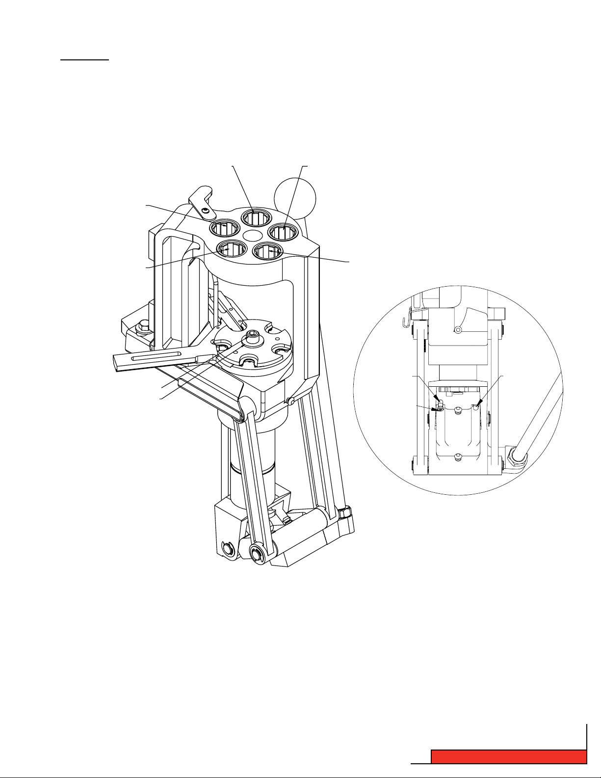
Figure 3: Removing Shell Plate
STATION 1
STATION 5
SHELL PLATE RETAINER BOLT (9)
FLAT WASHER (28)
STATION 2
STATION 3
STATION 4
LEFT PAWL
ADJUSTMENT
RIGHT PAWL
PAWL
SCREW
2B: Removing the Shell Plate
•
Use a 5/16" Allen wrench to remove the Bolt (9)
and to remove the shell plate.
•
Remove the Case Retainer Spring (17)
- 9 -
Lock-N-Load® AP Reloading Press
Page 10

SHELL PLATE TROUBLESHOOTING
•If the timing is severely out of adjustment, the Index Pawls (32) may have been damaged as outlined on page 9.
•If the Shell Plate does not rotate freely after mounting, check for these conditions:
•You may be trying to use the wrong version of shell plate. Your shell plate must have a groove cut on the bottom side.
•Dirt or debris between the shell plate and the drive hub.
•The Ball Detent bodies are not below flush on the underside of the Shell Plate.
•The Shell Plate is warped or damaged.
• If you reach a point where you cannot get the press to work, please call our technical service staff at
800-338-3220 or email webmaster@hornady.com.
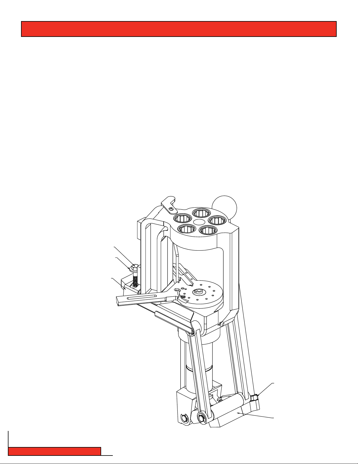
Step 3: Operation of your Lock-N-Load® Auto Progressive Press
The Hornady Lock-N-Load AP utilizes a high strength aluminum alloy frame with a compound linkage system which
operates the 2" diameter cylindrical ram. The Ram houses a drive shaft that is attached to the shell plate at the upper
end and the index wheel at the lower end. The toggle contains two spring actuated pawls which alternately engage the
index wheel to advance the shell plate through the different reloading stations.
As the handle is lowered, the right Pawl contacts the Index Wheel, advancing the Shell Plate during the first 1½" of
upward travel of the Ram. With this upward travel, the cases become aligned with the dies at the top of the Press. As the
Shell Plate comes to the top of the press, it guides the cartridge cases into the five die stations to perform the reloading
operations except priming.
The handle is then raised to complete the stroke, lowering the Shell Plate. When the Shell Plate comes to within 1 3/4" of
the bottom, the left Pawl engages the Index Wheel which advances the Shell Plate into position over the primer to seat it
into the case that was just sized and de-primed. Pushing back on the handle with moderate force will seat the new primer
into the case.
Once the dies are in place, and all stations are filled, the proper sequence for reloading is listed below.
•Place an empty case into station one. (Using the optional LNL-AP Case Feeder, this step is automatically done for you.)
•Insert bullet into the powder charged case in station four.
•Lower the handle.
•Powder drops into the newly primed case at station three.
•Raise the handle and seat a new primer in the de-primed case that has now moved to station two.
•Loaded cartridge is automatically ejected at station five when handle is raised.
Lock-N-Load® AP Reloading Press
- 10 -
Page 11

Step 4: Automatic Primer Feed Assembly
4A: Installing the Primer Body (see drawing on next page
•Place the aligning pin, located on the underside of the Primer Body (14) in the hole on the Sub-Plate (24) located next to
the Primer Slide (15).
•Insert the Cap Screw (11) thru the hole of the Primer Body (14) and screw it into the Sub-Plate (24).
•Rotate the Primer Body (14) counterclockwise towards the loader against the bolt and tighten the bolt.
4B: Installing the Primer Slide, Large or Small
•Lower the handle (44).
•Place a 2" spacer under the Sub-Plate (24); a 4" section of a 2" wide wooden block works well.
•Place the Primer Slide (15) flat side up in the groove on the Sub-Plate (24) and slide forward. The bump on the bottom
side of the slide is the travel stop as well as an alignment guide while the slide is in the retracted position.
•Attach the Spring (16) to the Sub-Plate (24) with the open end up (you may need to use needle nose pliers).
Attach the other end of the Spring to the pin on the Primer Slide.
4C: Installing the Primer Punch Assembly, Large or Small
•Raise the Ram (37) to the top of the stroke.
•Screw the Primer Seater Punch (26) into the Sub-Plate (24) from the bottom side.
•Tighten the Primer Seater Punch assembly (26) until it is snug using a wrench. (Do not over tighten the Primer Punch)
4D: Installing the Primer Tubes
•Place the tube of your choice (large or small primers) (4 or 5) in the center hole of the Primer Body (14) with the shoulder
section of the tube facing down. Make sure the tube is fully seated in the Primer Body.
4E: Installing the Primer Tube Housing
•Slip the threaded end of the Primer Tube Housing (6) over the Primer tube (4 or 5) and onto the Primer Body (14).
•Screw the Primer Tube Housing (6) on to the Primer Body (14) clockwise. Snug the tube by hand.
- 11 -
Lock-N-Load® AP Reloading Press
Page 12
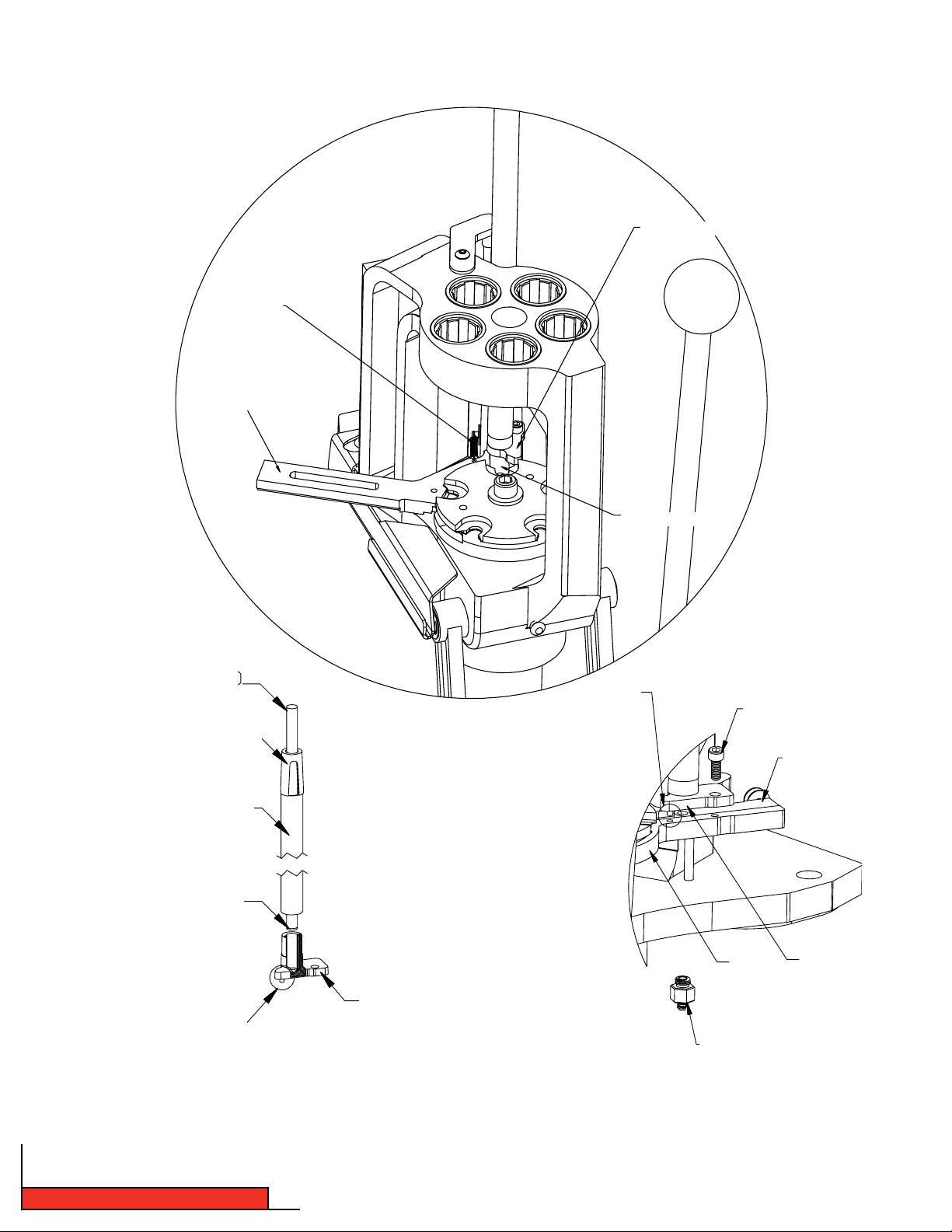
SPRING (16)
SUB-PLATE (24)
Figure 4: Primer Feed System
PRIMER BODY (14)
(10)
PRIMER TUBE SUPPORT (1)
PRIMER FEED TUBE (4 or 5)
“SHOULDERED END DOWN”
PRIMER FEED TUBE (4 or 5)
“SHOULDERED END DOWN”
PRIMER SLIDE (15)
ALIGNING PIN
CAP SCREW (11)
PRIMER SLIDE (15)
PRIMER BODY (14)
SUB-PLATE (24)
PRIMER FEED TUBE (4 or 5)
“SHOULDERED END DOWN”
4F: Primer Tube Support installation
•
Place the Primer Tube Support (1) over the Primer Feed Tube (4 or 5) and slip the three tapered “fingers”
inside the Primer Tube Housing (6). This will create a recess that allows the Primer Filler Tube (2 or 3) to
properly align with the Primer Feed tube during refillings.
Lock-N-Load® AP Reloading Press
PRIMER BODY (14)
PRIMER SEATER PUNCH (26)
- 12 -
Page 13
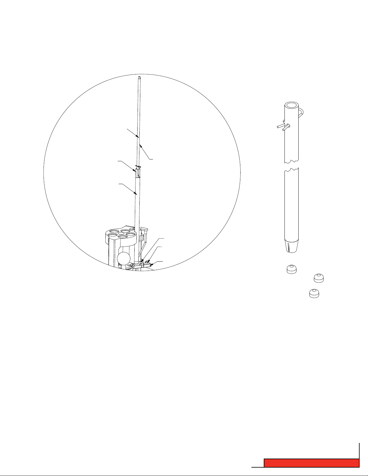
Step 5: Loading the Primer Tube
Refer to Step 4D for Primer Tube installation instructions.
PRIMER FILLER TUBE (2 or 3)
PRIMER FILLER TUBE (2 or 3)
PRIMER TUBE SUPPORT (1)
PRIMER TUBE HOUSING (6)
Figure 5: Filling the Priming System
PRIMER FEED TUBE (4 OR 5)
14
4
24
Carefully transfer the primers out of their factory package into a Hornady Primer Turning Plate and orientate them
shiny side up. Then holding the Primer Filler Tube (2 or 3) like a pencil, bring the plastic primer pick up tip over each
primer and gently press it over the primers. The primers will be pushed into the filler tube one on top of another.
Continue loading the primer filler tube until you have picked up approximately 100 primers.
Make sure the cotter pin is in place; turn the Primer Filler Tube (2 or 3) upside down. At the top of the exposed
Primer Filler Tube, there may be several primers still held and visible. Gently shake the tube to release the primers.
Align the Primer Filler Tube (2 or 3) to the Primer Feed Tube (4 or 5) using the Primer Tube Support (1). Remove the
cotter pin from the Primer Filler Tube (2 or 3) and fill the Primer Feed Tube (4 or 5). The primer tube has a 100
primer capacity. Do not over fill the primer tube.
Insert the Primer Fouler (10) into the Primer Feed Tube (4 or 5). This will help the primers feed more reliably.
- 13 -
Lock-N-Load® AP Reloading Press
Page 14
Step 6: Changing Primer Tubes
When changing to a different size of primer, you need to change the Primer Feed Tube ( 4 or 5), Primer Slide (15) and Punch
Assembly (26).
If there are primers in the Primer Feed Tube (4 or 5), you will need to empty it before changing the tubes. Remove the Cap
Screw (11), cup your hand under the Primer Tube and rotate the Primer Feed Body Assembly clockwise to catch the primers.
After the tube is empty, rotate the body back in place and re-install the mounting screw. Refer to Step 4 for more details.
Disconnect the Spring (16) from the roller pin and remove the Primer Slide (15). Remove the Primer Tube Support (1) and the
Primer Feed Tube (4 or 5).
If the primer tube is empty, there is no need to take the primer feed assembly off of the sub-plate. Remove the Primer
Feed Support (1), Primer Tube (4 or 5), disconnect the Spring (16) and remove the Primer Slide (15) and Punch Assembly
(26). Reinstall the primer system for your application (Refer to Step 4). Fill the primer tube as previously described (Refer to
Step 5).
The Primer Seater Punches (26) are installed from the bottom side of the Sub-Plate (24). Raise the Ram (37) to the top of
the stroke. Use a wrench to loosen the Primer Seater Punch (26) and unscrew it from the Sub-Plate (24). When installing a
new Primer Seater Punch (26), tighten it snug with a wrench. Do not over tighten the Primer Punch.
(10)
PRIMER TUBE SUPPORT (1)
PRIMER FEED TUBE (4 or 5)
“SHOULDERED END DOWN”
PRIMER FEED TUBE (4 or 5)
“SHOULDERED END DOWN”
SPRING (16)
SUB-PLATE (24)
PRIMER BODY (14)
PRIMER SLIDE (15)
ALIGNING PIN
CAP SCREW (11)
SUB-PLATE (24)
PRIMER SLIDE (15)
PRIMER
BODY (14)
PRIMER FEED TUBE (4 or 5)
“SHOULDERED END DOWN”
Lock-N-Load® AP Reloading Press
PRIMER BODY (14)
PRIMER SEATER PUNCH (26)
- 14 -
Page 15
Step 7: Automatic Primer Feed Inspection
It is not necessary to install the primer tubes at this time to test your loader, but you must install the Primer Body (14).
Lower the Primer Slide (15) so that is stays in place. See step 4A for instructions on installing the Primer Body (14).
At this point you should have installed a Shell Plate and the corresponding Primer Seater Punch (26) and Primer Slide (15)
for the cartridge you are loading.
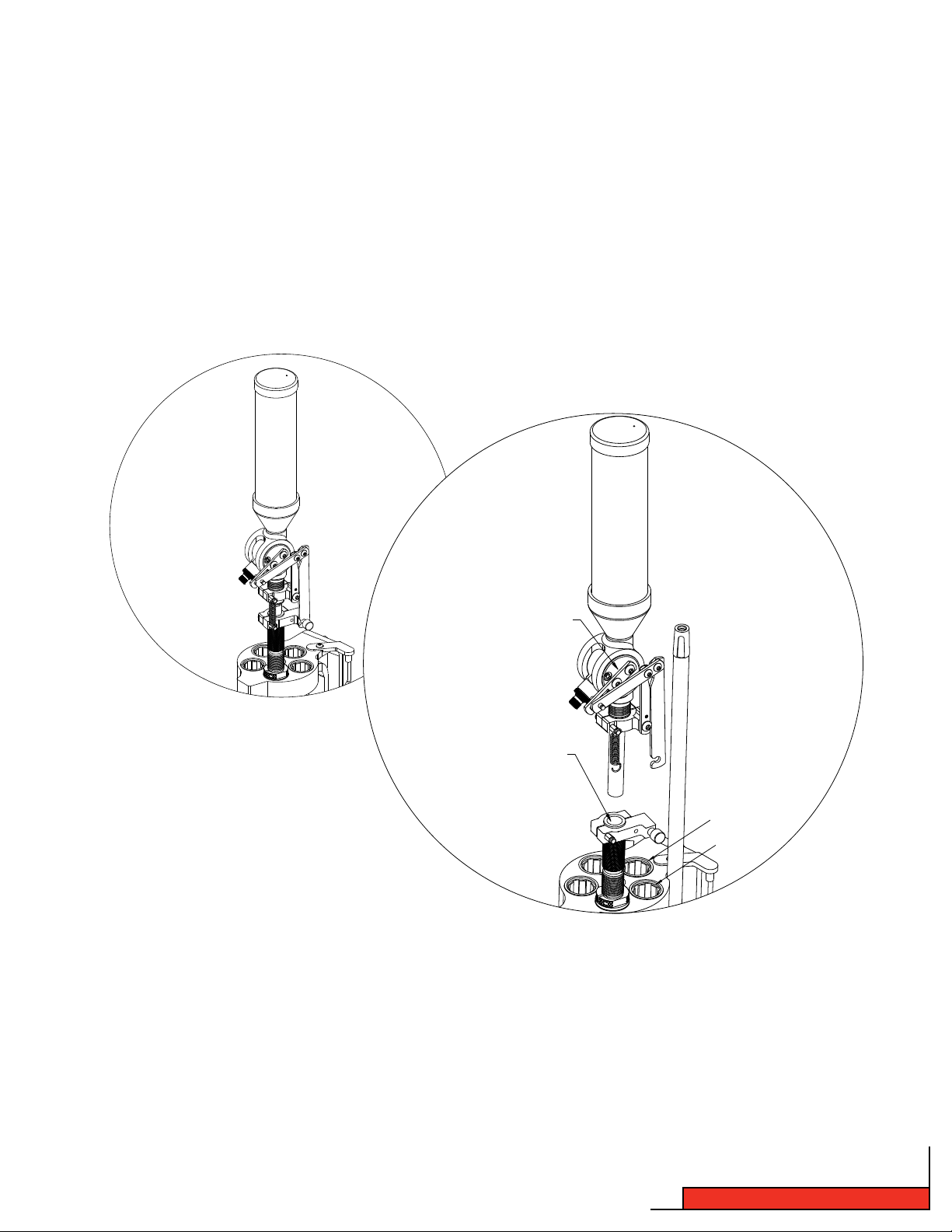
Step 8: Installing the Lock-N-Load® Powder Measure with Case Activated Powder Drop.
Figure 6: Lock-N-Load Powder Measure
UPPER ASSEMBLY
MEASURE ADAPTER
STATION 1
STATION 2
The Lock-N-Load Powder Measure combines with the Case Activated Powder Drop to mount on-top of the Lock-N-Load AP in
station 2 or 3. The Lock-N-Load Powder Measure that was shipped with the press has been factory fitted with the case
activiated
Powder Drop.
* This press comes packaged with the Standard Rotor & Standard Metering Insert and the Pistol Rotor & Pistol Metering Insert.
Refer to the Lock-N-Load Powder Measure and Case Activated Powder Drop instructions for cleaning and functionality.
(These instructions are included).
- 15 -
Lock-N-Load® AP Reloading Press
Page 16
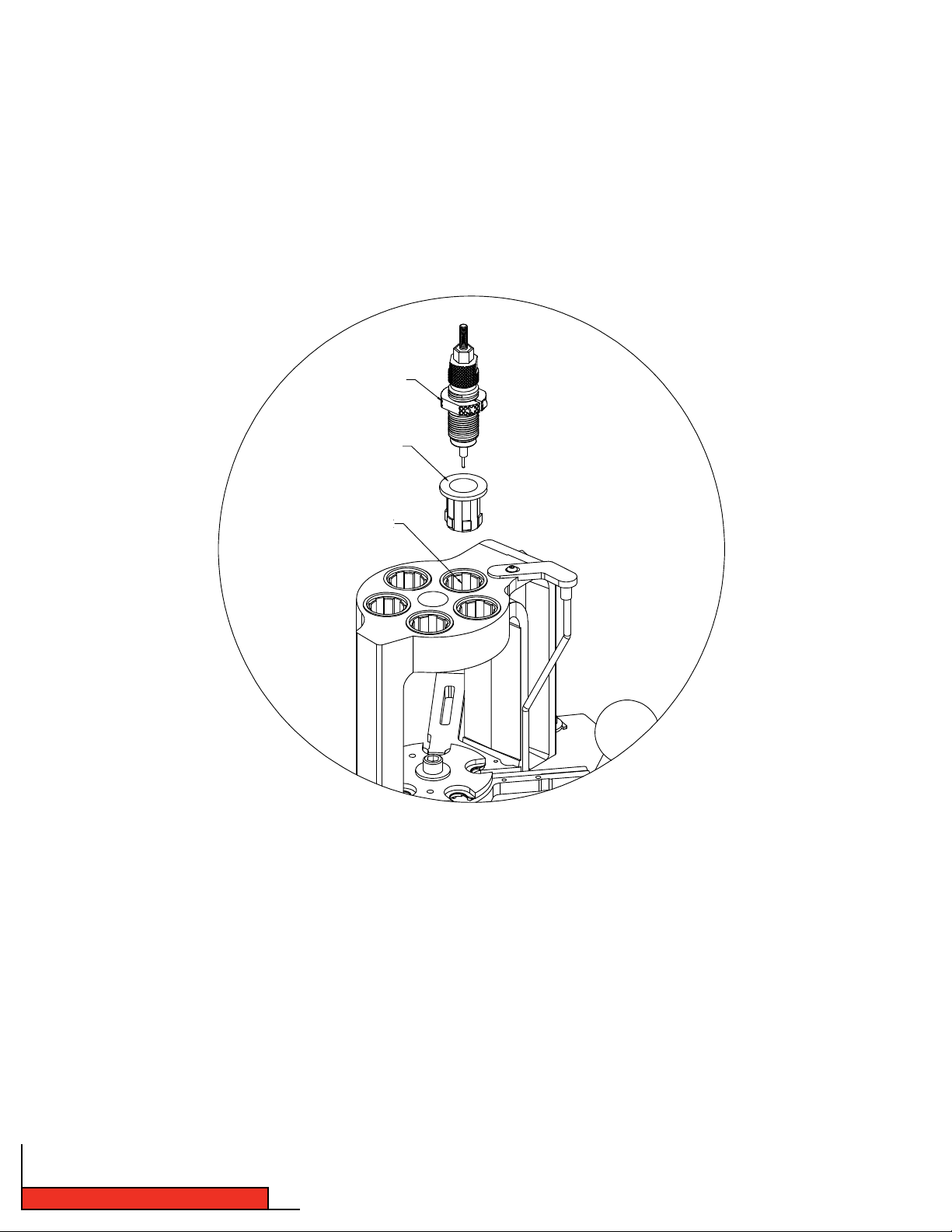
Step 9: Lock-N-Load® quick change bushing system
The Lock-N-Load system is based on the positive locking action of the bolt action rifle. Just like the bolt action rifle,
the locking action is incredibly strong and simple.
Once the dies and the powder measure are adjusted for loading, these settings are locked in place by tightening
the Lock Ring that is provided with all Hornady dies and powder measures.
How the Lock-N-Load® works:
LOCK-N-LOAD BUSHING
BUSHING/RECPTACLE
Figure 7: Hornady Lock-N-Load System
LOCK RING
LOCK-N-LOAD
LOCK-N-LOAD BUSHING THREADS
ONTO STANDARD 7/8"-14 TPI
RELOADING DIES.
•Insert the Lock-N-Load bushing into the press and turn it clock wise to lock it in place.
•Adjust the die to the desired position and lock the setting in place with the die’s lock ring.
Once Lock-N-Load bushings are installed, Dies and Powder Drop can be removed from the press with a quick
counterclockwise turn. Since the Lock-N-Load bushing is locked in place, the dies and the Powder Drop remain set
exactly as you left them.
For added speed and convenience, Hornady offers inexpensive Quick Change Powder Dies for use with the Case
Activated Powder Drop.
Step 10: Die Mounting Instructions
For initial die cleaning and set-up instructions, please refer to the instruction sheet that came with your die set.
Please Note: The Hornady Lock-N-Load Auto Progressive with EZject™ System can use any brand of die.
Lock-N-Load® AP Reloading Press
- 16 -
Page 17

Step 11: Preparing to Load
Start with a single empty cartridge case and run it through all the loading stations (see Step 3 for details). This will
allow you to check your adjustments. Refer to instructions provided with the die set for set up and proper adjustment.
• Sizing a case.
n
Make sure the sizing die is adjusted properly, and the de-priming pin knocks out the old primer.
• Seating a primer.
n
Check and make sure the Primer Slide (15) picked up a primer from the Primer Feed Tube (4 or 5).
n
When you cycle the press and the handle comes to a stop, you will have to push the handle away from you past
the stop to seat the primer. Push until it stops but don’t force it. Seating the primer requires a firm push.
n
Lower the handle of the press slowly to rotate the shell plate to start the next operation. If there is resistance on
the shell plate, the primer is improperly seated and not allowing the Shell Plate to rotate.
• Drop powder in the case using the case activated powder drop.
n
Verify the weight on a properly calibrated scale.
• Seat a bullet in the powder charged case.
n
Begin lowering the handle to rotate the shell plate to this station.
n
Place a bullet on top of the case and lower the handle the rest of the way. (You may need to position the bullet
over the case neck between your thumb and forefinger until the bullet enters the alignment sleeve).
• Station 5. (Refer to illustration on page 6)
n
This station is used for a Taper Crimp Die when reloading pistol cartridges that headspace off the case mouth.
* Any manufacturer’s Taper Crimp Die will work in Station 5 with the AP’s EZject™ System.
n
Properly adjusted, a taper crimp die removes all case-flare from the expander die without damaging or
squeezing into the bullet.
Lower the handler to advance the shell plate to the next station. The loaded round will rotate and contact the EZject
System underneath the shell plate. This EZject™ System will automatically eject the loaded round from the press.
Never force the handle. Measure the case for proper length and check the data in your reloading book.
When you are satisfied with the first completed cartridge, repeat the process with another single case, advancing
slowly from station to station until you eject the finished cartridge from the press with the case ejector.
After you are comfortable with the process, load the press with consecutive cases for reloading. Do not rush! After
you advance the cases through each station, inspect everything to insure proper function. If anything looks out of
place, or if you lose track of what you are doing, STOP! It’s safer to begin slowly than it is to assume you need to
reload a large number of cartridges during each session. Don’t force the handle at any time, and be sure that all
mechanical parts are properly lubed.
SAFETY NOTE: Be safe! Double check your powder loads at frequent intervals to insure the powder charge is
working properly.
™
- 17 -
Lock-N-Load® AP Reloading Press
Page 18
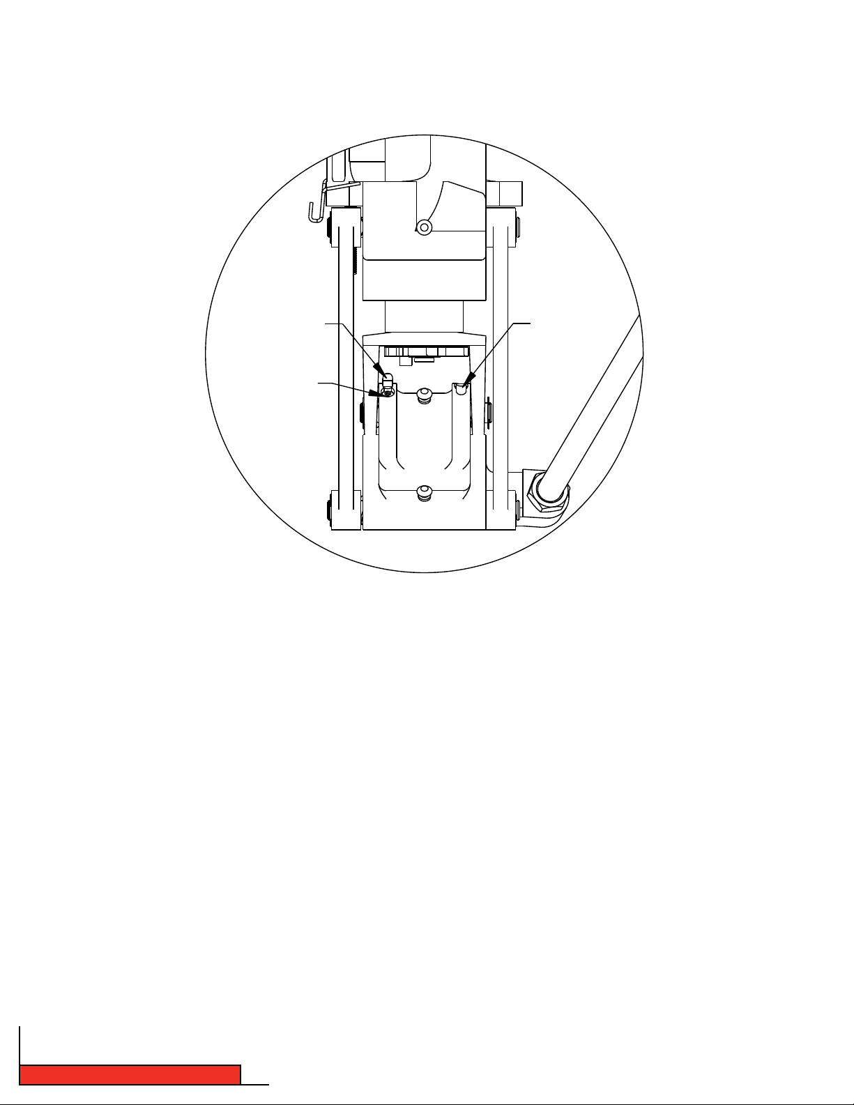
Step 12: Adjusting the Auto Advance Mechanism
Figure 8: Pawl Adjustment
LEFT PAWL (32)
PAWL ADJUSTMENT
SCREW
RIGHT PAWL (32)
The Auto Advance Mechanism is fully adjusted at the Hornady factory and should not require further adjustment. If you
feel your shell plate is not advancing properly, check all other options listed in this manual before attempting to adjust
the mechanism’s pawls.
All adjustments should be made in extremely small increments.
Through everyday use, the pawls on your press may gradually wear and may need to be adjusted. Before making
adjustments you should understand what each pawl does.
As the operating handle is lowered and raised through a complete cycle, each pawl engages the index wheel at the
bottom of the press. The index wheel is connected through the driveshaft to the shell plate. As each pawl engages the
index wheel it advances the shell plate either at the top or bottom of the cycle.
The right pawl (as you face the press) advances the shell plate as the ram travels up when the handle is pulled down.
The left pawl advances the wheel on the down stroke of the handle and should advance the shell plate to the detent
holes in the sub-plate. If the shell plate doesn’t advance enough on the down stroke of the ram, only the left pawl needs
adjustment.
Lock-N-Load® AP Reloading Press
- 18 -
Page 19

The right pawl is too low if the shell plate stops short of the detent, which can be felt as you rotate the shell
plate into place by hand in a clockwise direction. If the pawl is too high, you will feel a slight double click on the
handle as the pawl disengages and the shell plate is locked into place by the detents.
The same is true for the left pawl which indexes on the up stroke of the handle (down stroke of the ram.)
Likewise, if the plate doesn’t advance far enough on the up stroke of the ram, only the right pawl needs to be
adjusted. Don’t assume that both pawls need adjusting.
Do only one pawl at a time to keep from becoming confused.
The height of each pawl determines how far the shell plate will advance when that pawl comes in contact with
the indexing wheel. To adjust the pawls, increase the height of the chosen pawl to increase the advancement of
the shell plate in that direction or decrease the height of the pawl to decrease the shell plate advancement in
that direction.
There is a set screw on each pawl, refer to (Figure 8).
•Turnthesetscrewclockwisetolowerthepawl.
•Turnthesetscrewcounterclockwisetoraisethepawl.
Become familiar with these pawls from the onset and see how they operate. You will then find it much easier
to adjust the pawls, should you need to do so in the future.
MAINTENANCE OF THE LOCK-N-LOAD® AP
As with all machinery, proper routine maintenance will provide smooth operation and a longer life for your
reloading press. Check all moving parts for dirt or spilled powder and remove with a clean shop rag.
Remove the primer slide, shell plate and clean the spilled powder under it. After cleaning, lubricate the
sub-plate in the area of the detents, drive hub and sub-plate with one or two drops of light grade machine oil or
Hornady One Shot Gun Cleaner and Dry Lube. The primer slide is permanently lubricated and needs no oil.
Lightly lube the index wheel and pawls. Hornady One Shot Gun Cleaner and Dry Lube is excellent to use here. It is
a dry lube, so stray powder won’t stick to it while you’re reloading.
- 19 -
Lock-N-Load® AP Reloading Press
Page 20

TIPS FOR TROUBLE-FREE OPERATION
PROBLEMS SOLUTIONS
Powder dropping around case Correct bushing in place?
Powder drop tube and measure adapter clean?
Bushing installed deep counter sink side up?
No primer in case Primer slide properly adjusted?
Correct primer punch installed?
Primer slide spring in place?
Correct primer slide installed?
Primer body rotated counterclockwise when installed?
Shell Plate will not advance or does
not index on station
Primer not fully seated?
Pawls correctly adjusted?
Make sure you have the latest shell plate version with the
groove on the bottom side.
Cases do not feed into Dies Die mouths beveled? (If not, return to manufacturer for repair.)
Pawls timed correctly?
Gun powder is sticking in the
powder measure, or inconsistent
charge weights
Is the inside surface dry and clean?
Try pouring a little powdered graphite thru the powder measure for
lubricant. Rub the outside of the powder hopper with a dryer sheet
to eliminate static.
Case retainer spring won’t fall off
the shell plate or it is getting kinked
Is there a burr on the shell plate where the spring groove and the
case location meet?
Is there a burr on the sides of the slot on the sub-plate? (With a
casefeeder, when you are setting up the timing, do not run the case
into the spring if the spring is up on the shell plate.)
Lock-N-Load® AP Reloading Press
- 20 -
Page 21
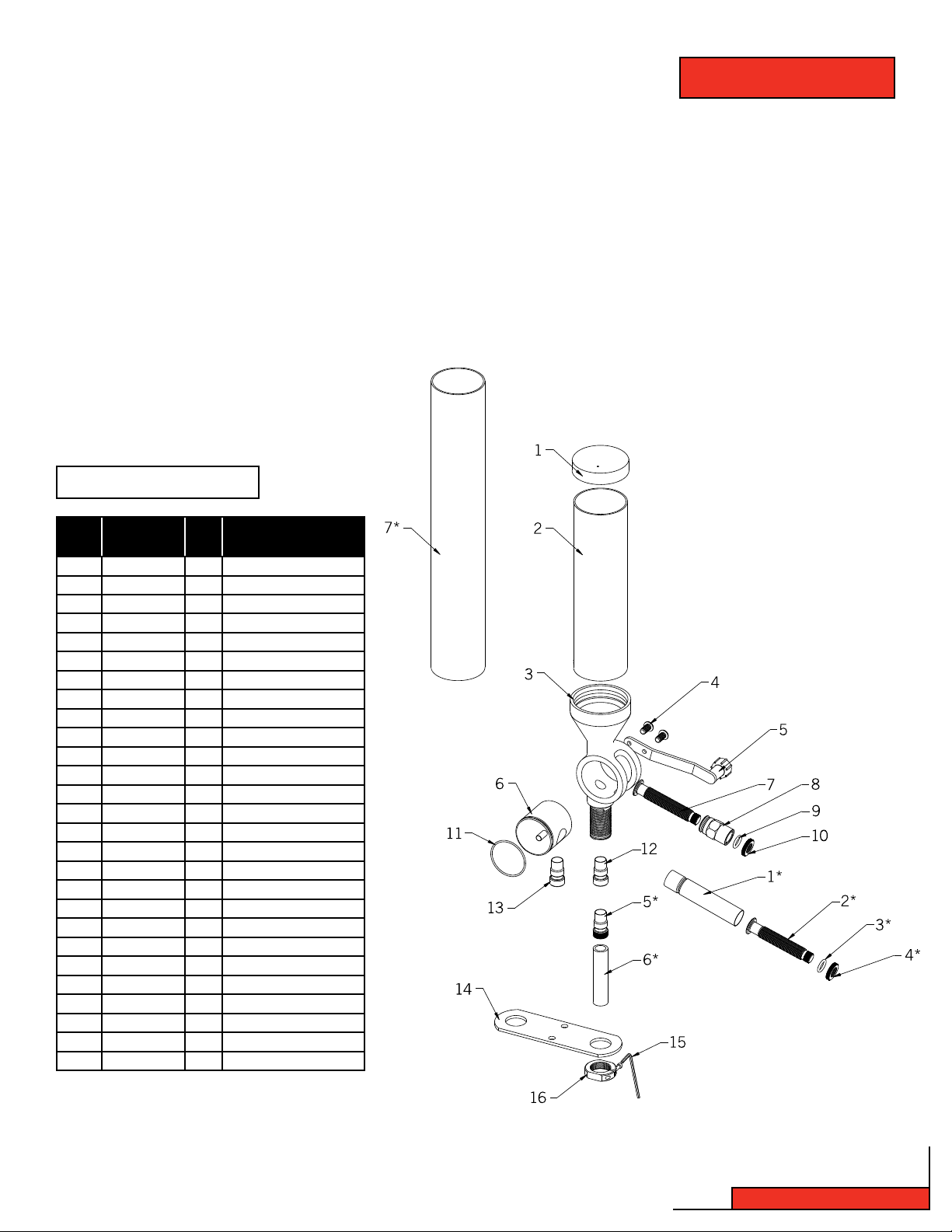
TABLE OF CONTENTS
Steps Page
Overview........................................................22
1: Disassemble ...........................................22
2: Assemble ................................................23
3: Operate and Adjustment.........................23
4: Precautions ............................................23
BILL OF MATERIALS
Item
(*)’s are for 50 BMG Powder Measure
Production
No.
Part Number
1 170405 1 HOPPER CAP
2 398520 1 HOPPER
3 392740 1 BODY
4 392719 2 SCREW BHSCS 10-32 X 3/8
5 392752 1 HANDLE ASSEMBLY
6 392741 1 ROTOR
7 392743 1 METERING PLUNGER
8 392742 1 SLEEVE
9 480083 1 O-RING 1/2 ID X 11/16 OD
10 392764 1 NUT LOCK METERING UNIT
11 392766 1 O-RING 1 1/2 ID X 1 5/8 OD
12 390702 1 SMALL DROP TUBE
13 390701 1 LARGE DROP TUBE
14 392760 1 MOUNTING BRACKET
15 390656 1 3/32” HEX WRENCH
16 O44000 1 LOCK RING
17 390653 1 1/8” HEX WRENCH
1* 392779 1 BODY 165-265
2* 392780 1 PLUNGER, HIGH CAPACITY
3* 480083 1 O-RING 1/2 ID X 11/16 OD
4* 392764 1 NUT LOCK METERING UNIT
5* 392777 1 ADAPTER
6* 392775 1 TUBE DROP
7* 398521 1 HOPPER
8* 390653 1 1/8” HEX WRENCH
9* 390656 1 3/32” HEX WRENCH
10* 390036 1 5/32” HEX WRENCH
Qty. Description
Lock-N-Load
®
Powder Measure
Charts
1. Bill of Materials of
Lock-N-Load Powder Measure ................21
2. Exploded view of
Lock-N-Load Powder Measure ................21
- 21 -
Lock-N-Load® Powder Measure
Page 22

OVERVIEW: LOCK-N-LOAD® POWDER MEASURE
Your Powder Measure has been treated with a rust preventative which must be removed before use. We
recommend that you clean and degrease all metal parts with Hornady One-Shot Cleaner and Dry Lube.
TO DISASSEMBLE:
•Set the Rotor with the Metering Unit perpendicular to the axis
of the Body, press the Push Button and hold it down while
removing the Metering Unit.
NOTE: Do NOT remove push button. It is permanently installed
and does not need cleaning.
•Remove the Handle, or Rotating Arm from the Powder Measure, by removing the two attaching screws with a 1/8” hex
wrench.
•Slide the Rotor out of the Body by pressing gently on the
handle side of the Rotor.
Be careful not to drop or otherwise damage the Rotor while
it is out of the Body.
•Remove the Lock Nut, O-Ring and Sleeve from the Metering
Plunger. Spray all metal parts liberally with Hornady One ShotGun Cleaner and Dry Lube. Be sure all rust preventatives are
removed.
•Allow it to dry thoroughly before reassembling.
Lock-N-Load® Powder Measure
- 22 -
Page 23

TO ASSEMBLE:
Reverse the procedure in the first five steps above.
The Rotor and Body are very closely fit and must be properly aligned to reassemble.
DO NOT FORCE IT OR IRREPAIRABLE DAMAGE WILL OCCUR.
TO OPERATE AND ADJUST:
•
Attach the Mounting Bracket to your bench or shelf using (2) #14 Binding Head Sheet Metal Screws or other suitable
hardware. The screws should be approximately _” back from the edge of the bench, and the smaller of the two large holes
should be suspended off of the bench.
•Place the Powder Measure in the hole of the Mounting Plate, thread the Lock Ring onto the Powder Measure, tighten the
Lock Ring to the Mounting Plate and lock it in place with the 3/32” hex wrench, if desired.
•Select the appropriate Drop Tube (The smaller for 20 and 25 caliber, the larger for 6.5 mm and up) and thread it into the
bottom of the Powder Measure until it is secure against the internal shoulder. (Finger tight is all that is required.)
•The Lock Nut and O-ring on the Metering Unit may be adjusted to provide tension on the thread of the Plunger, so as to
allow setting it while not allowing unintentional movement in operation. It may be locked in place by tightening when
adjustment is achieved.
One revolution of the plunger is .05” travel. With the plunger all the way in, or the capacity set to near zero, the end of
the thread and the outer surface of the Lock Nut should be approximately flush.
With the plunger all the way out (roughly 20 turns, 1”), the maximum capacity is approximately 100 grains or 5 grains
per turn.
•Once your Metering Unit is set, lock it, label it and store it with the die set, for the fastest possible return to the present
setting in future loading sessions.
PRECAUTIONS:
Always change the metering units with the handle and the metering unit in the horizontal position, and after you
have dropped the charge. If you allow the Handle to fall while changing units, you will drain the Hopper.
Be sure that you have the proper “Lock-N-Load” device locked in place, before operating.
Always verify your charges with a scale before loading.
Any moisture in the unit will cause powder to stick, and charge weights will vary dramatically.
- 23 -
Lock-N-Load® Powder Measure
Page 24

TABLE OF CONTENTS
Lock-N-Load
Case Activated Powder Drop
Steps Page
Overview............................................................................ 25
1: Assembling the Case Activated
Powder Drop Rotor Arm ................................................. 25
2: Upper Bracket Assembly ............................................... 26
3: Drop Tube Installation...................................................27
4: Installing the Case ActivatedPowder Drop .................... 27
(Lower Assembly)
5: Final Powder Measure Assembly ................................... 28
6: Case Activated Powder Drop Adjustment ...................... 28
BILL OF MATERIALS
®
Figures
1. Attaching the Case Activated Powder Drop Rotor Arm ..10
2. Upper Bracket Assembly ............................................... 11
3. Drop Tube Installation...................................................12
4. Installation for the Case Activated Powder Drop ........... 14
(Lower Assembly)
5. Final Powder Measure Assembly ................................... 15
Charts
1. Bill of Materials for Case Activated Powder Drop .......... 24
2. Exploded view for Case Activated Powder Drop ............. 24
6
5
Item
* (Sold Separately)
Production
No.
Part Number
1 392721 4 BHSCS 10-32 X 1.00
2 392708 2 MOUNTING CLAMP
3 392710 1 ROTOR ARM
4 392719 5 BHSCS 10-32 X 3/8
5 392715 2 SHOULDER NUT
6 398735 1 PIVOT
7 398737 1 DRIVE LINK
8 398736 1 MEASURE LINK
9 398742 2 BHSCS 10-32 X 1.25
10 392717 1 GROOVE PIN 3/16 X 7/8
11 392718 1 SPRING PIN 1/8 X 3/8
12 392707 1 UPPER BRACKET
13 398739 2 SPRING NUT
14 391008 1 RETURN SPRING
15 392705 1 DROP TUBE
16* 392703 1 17 CAL. SLEEVE
17 392701 1 #1 POWDER SLEEVE
18 392702 1 #2 POWDER SLEEVE
19 392700 1 PISTOL POWDER SLEEVE
20* 290040 1 .355 POWDER THRU EXPANDER
20* 290041 1 .357 POWDER THRU EXPANDER
20* 290042 1 .400 POWDER THRU EXPANDER
20* 290043 1 .430 POWDER THRU EXPANDER
20* 290044 1 .451/.452 POWDER THRU EXPANDER
20* 290045 1 .475 POWDER THRU EXPANDER
20* 290048 1 .500 POWDER THRU EXPANDER
21 392704 1 MEASURE ADAPTER
22 392706 1 LOWER BRACKET
23 398741 1 LOCKING BOLT
24 392722 1 RETAINING RING
25 O44000 1 LOCK RING
26 392302 1 LOCK -N-LOAD BUSHING
Qty. Description
12
4
7
8
10
13
14
15
20
22
13
11
4
23
1
9
16*
1
9
2
17
25
26
24
21
2
18
3
19
Lock-N-Load® Powder Measure
- 24 -
Page 25

OVERVIEW: CASE ACTIVATED POWDER DROP
The Case Activated Powder Drop helps make reloading faster
and easier than ever before. It automatically activates
and dispenses a charge with every pull of the handle,
but only when a case is present in the station. Plus, it
works with Lock-N-Load bushings. (You can remove
and change Hornady powder measures with a quick
turn, without changing adjustments.) The Case
Activated Powder Drop unit can be used ONLY on
the Hornady Lock-N-Load Powder Measure.
Before using, disassemble and carefully clean
the inside surfaces of the drop tube, measure
adapter and powder sleeves. Rust preventative oil
was applied at the factory to protect the parts during
shipment and must be removed before reloading.
Brake cleaner works well to remove the oil.
Step 1: Assembling the Case Activated
Powder Drop Rotor Arm
Reinstall the Rotor with the handle side to the
right (metering opening facing you).
Place the Metering Unit back into the Rotor.
Attach the Case Activated Powder Drop Rotor
Arm (#3) to the right side of the Rotor using
two Button Head Cap Screws (#4).
L-N-L POWDER MEASURE
Fig. 1: Attaching the Case Activated
Powder Drop Rotor Arm
- 25 -
Lock-N-Load® Case Activated Power Drop
Page 26

Step 2: Upper Bracket Assembly
Slide the Upper Bracket Assembly onto the Powder Measure.
Engage Drive Link Pin (#10) into the Rotor Arm Slot.
Adjust the position of the Upper Assembly so that the drive link pivot is across from the centerline.
Tighten the two Button Head Cap Screws (#1) and (#9). The longest screw 10-32 X 1.25 goes in the front hole. Screw
on the Spring Nut (#13) to the end of the 10-32 X 1.25 screw.
Figure 2: Upper Bracket Assembly
ROTOR
ARM SLOT
DRIVE LINK PIN
9
2
UPPER ASSEMBLY
L-N-L POWDER MEASURE
ROTOR “CENTERED”
PIVOT LOCATED
ACROSS FROM
ROTOR CENTERLINE
Lock-N-Load® Case Activated Power Drop
- 26 -
Page 27

Step 3: Drop Tube Installation
Screw the Drop Tube (#16) into the bottom of
the Powder Measure.
Lubricate the exterior of the Drop Tube (#16)
with Hornady One Shot Gun Cleaner and Dry
Lube or other similar dry lubricant.
L-N-L POWDER MEASURE
ROTOR “CENTERED”
Figure 3: Drop Tube Installation
16
PIVOT LOCATED
ACROSS FROM
ROTOR CENTERLINE
Step 4: Installing the Case Activated Powder Drop (Lower Assembly)
Screw the Measure Adapter (Lower Assembly) into the reloading press a couple of turns.
Select the appropriate powder bushing sleeve for your application. (Each sleeve has a shallow countersink on one side,
and a deep counter sink on the other.) Insert the bushing, with the deep counter sink facing up, into the top of the measure adapter.
If using a Drop Thru Expander Powder Sleeve, insert the Expander with the deep countersink facing up, into the top of the
Measure Adapter.
The Case Activated Powder Drop comes with three internal powder bushing sleeves. The longest is the pistol powder sleeve
(#20). Powder sleeve (#19) has the smallest inside diameter and works for loading 20 to 270 caliber rifle cases. The third
and shortest powder sleeve is for loading 7MM to 45 caliber rifle cases.
Figure 4: Installation for the Case
Activated Powder Drop (Lower Assembly)
POWDER BUSHING
MEASURE ADAPTER
- 27 -
MEASURE ADAPTER
Lock-N-Load® Case Activated Power Drop
Page 28

Step 5: Final Powder Measure Assembly
Insert the Powder Drop Tube (#16) into the lower assembly. (Refer to pg. 13)
Connect the slot on the Measure Link (#8), (Refer to pgs. 17 & 18 for more details).
UPPER ASSEMBLY
Figure 5: Final Powder Measure Assembly
MEASURE ADAPTER
Step 6: Case Activated Powder Drop Adjustments
Insert a case into the shell plate at station 3 of your Lock-N-Load AP and operate the handle to raise the ram to its highest
position. (refer to pg. 13 in your Lock-N-Load AP manual)
Lower the Powder Measure by rotating it Clock-Wise (CW) into the press until the Powder Measure Rotor is fully rotated,
but not contacting the end of the slot in the Powder Measure Body.
Lower the Ram and attach the Return Spring (#14) between the two Spring Pins (#13).
Check the adjustment for correct positioning and secure the adjustment with the lock ring.
Clean the Case Activated Powder Drop at the end of each reloading session with a clean dry cloth to prevent a build up of
excess powder. This helps prevent the internal sleeve from sticking and spilling powder around the cartridge cases as they
are loaded.
Lock-N-Load® Case Activated Power Drop
- 28 -
Page 29

TABLE OF CONTENTS
Lock-N-Load
Auto Progressive Case Feeder
Steps
Overview........................................................................32
List of required hand tools ............................................32
1: Mounting the Lock-N-Load Auto Progressive
with Case Feeder ..................................................33
2: Changing the sub-plate .........................................34
3: Assemble the square tubing brackets ....................35
4: Placing the square tubing brackets
onto the square tubing ...........................................35
5: Assemble the square tubing and brackets
to the frame of the AP Press ...................................36
6: Assemble the square tubing to the frame
of the AP Press .......................................................37
7: Adding the case slide onto the sub-plate ...............37
8: Inserting the cam wire into the assembly ...............39
9: Case escapement bracket assembly ......................40
10: Mounting the Feed tube bracket to
the square tubing ...................................................41
Page
®
11: Determine which caliber you are going
to be loading ..........................................................42
12: Installing the V-block to the case slide ..................43
13: Changing and installing the shell plate .................43
14: Set the timing of the cam wire ...............................44
15: Assembling the feed tube end and pivot ................46
16: Placing the feed tube end on the assembly ............47
17: Selecting the case feed plate for
your application......................................................48
18: Adjusting the push rod ...........................................50
Single case operation ....................................................50
Fail-safe mechanism ....................................................50
Maintenance of the Lock-N-Load AP Case Feeder .........51
Trouble free operation....................................................51
List of Illustrations
Figures
1. AP with main bracket .............................................33
2. Spent primer tube dismantle/assembly ..................34
3. Square tubing brackets with set screws .................35
4. Square tubing brackets with square tubing ...........35
5. Square tubing brackets to AP Frame ......................36
6. Square tubing to AP Frame .....................................37
7a. Case slide assembly ...............................................37
7b. Case slide and sub-plate assembly .......................38
8. Assembly of cam wire .............................................39
9. Assembling case escapement bracket
on square tubing ...................................................40
Charts
1. Caliber change over chart .......................................42
2. Shell plate selection chart ........................................7
3. Case feed wheel selection chart .............................50
10. Feed tube mounting bracket to square tubing ........41
11. V-block selection ....................................................42
12. Inserting the V-block ..............................................43
13. Adjusting the V-block .............................................44
14. Feeding a case .......................................................44
15. Cam rod adjustment...............................................45
16. Pivot assembly .......................................................46
17a. Setting the feed tube end (most cases) ..............47
17b. Setting the feed tube end (357 Mag., etc.) ..........47
18. Case feed bowl door adjustment ............................49
19. Push rod adjustment ..............................................50
4. Trouble free operation .............................................51
5. Bill of Materials ......................................................30
6. Exploded view .........................................................31
- 29 -
Lock-N-Load® AP Case Feeder
Page 30

BILL OF MATERIALS: LOCK-N-LOAD® AP CASE FEEDER
Production
Item No.
1 398327 1 Case Feed Bowl
2 398313 4 10-32 x ¾ FHSCS
3 398374 8 10-24 “U” Nut
4 398415 8 #8 x 1/2 Sheet Metal Screw Pan Head Philips
5 398326 1 Motor Housing
6 398375 2 4-40 Hex Head Lock Nut
7 398333 1 Micro Switch
8 398369 1 Case Feed Funnel Assembly
9 398376 1 4-40 x 5/8 B HSCS
10 398332 2 Rocker Switch
11 398331 1 Motor
12 398328 1 Motor Cover
13 398320 1 Feed Tube-Large
14 398321 1 Feed Tube-Small
15 398303 1 Feed Tube End-Large
16 398286 1 Feed Tube Mounting Bracket
17 396440 2 Lock Ring
18 398298 1 Pivot Adapter
19 398290 1 Pivot
20 398310 1 1/4 - 3/4 Shoulder Bolt
21 398 311 1 3/0 x 3/4 Tper Pin
22 398305 1 Drop Tube-Large
23 398288 1 Spring, Tor sion
24 398317 1 Push Rod
25 398371 1 Push Rod Tip
26 390178 2 1/4-20 Hex Head Nut
27 398349 1 Push Rod Bushing
28 398364 1 10 x 1/2 Sheet Metal Screw Pan Head Philips
29 398344 1 Pivot Body
30 398363 1 Push Rod Spring
31 398343 1 Cam Wire Support
32 398425 1 E Clip 1/4
33 398373 1 Push Rod Nut
34 398372 1 Push Rod Lower
35 398314 2 5/16-18 x 5/8 Set Screw Cup
36 39 8315 2 5/16-18 x 5/8 Set Screw Cone Point (45 Deg.)
Part No. Qty. Description
Production
Item No.
37 398285 1 Case Feed Door Adjustment
38 398291 1 Case Slide
39 398307 1 Case Slide Rod Guide
40 398308 1 Case Slide Rod Guide Spring
41 39 2011 2 10-32 Hex Head Nut
42 398289 1 Main Bracket
43 398299 1 Cam Wire
44 398309R 1 Sub-Plate (on press or with retrofit kit)
45 398287 2 Bracket, Sq. Tubing
46 398345 1 Eject Wire (pre 7000 SER #)
47 398321 2 1/4-20 x 125SHCS
48 390128 4 1-4 Flaat Washer Zinc Plated
49 398284 1 Case Feed Stand
50 398304 1 Feed Tube End-Small
51 398300 1 Pivot Adapter Bushing
52 398301 1 Pivot Bushing
53 398306 1 Drop Tube-Small
54 095310 OPT Case Feed Plate-Small Pistol
55 095312 OPT Case Feed Plate-Large Pistol
56 095314 OPT Case Feed Plate-Small Rifle
57 0 95316 OPT Case Feed Plate-Large Rifle
58 059100 OPT AP Press
59 398346 1 10-24 x 1/2 SHCS
60 398293 1 V-Block #1
61 398297 1 V-Block #2
62 398294 1 V-Block #3
63 398292 1 V-Block #4
64 398295 1 V-Block # 5
65 398296 1 V-Block #6
66 398324 1 Plastic Feed Tube Small Bushing
67 390651 2 3/16" Flat Washer SAE
68 398362 1 10-24 x 5/16 B HSCS
69 398 370 1 Case Feed Bowl Bushing
70 398388 2 1/4-20 x 150 SHCS
71 398416 1 O-Ring 7/8 OD, 11/16 ID
72 398550 6 Rivet Poly Black
73 398302 OPT Intermediate Drop Tube
Part No. Qty. Description
Lock-N-Load® AP Case Feeder
Chart 5: Bill of Materials
(“*” Sold Separately) (“Italics” Pre Assembled)
OPT = Optional Accessory Sold Separately
- 30 -
Page 31

EXPLODED VIEW: LOCK-N-LOAD® AP CASE FEEDER
- 31 -
Lock-N-Load® AP Case Feeder
Page 32

OVERVIEW ON LOCK-N-LOAD
®
AUTO PROGRESSIVE (AP) CASE FEEDER
Your new AP Case Feeder has been packaged to insure minimal
vibration and damage during transportation.
Remove all the parts from the packing box and spread them out over
a large flat surface. Refer to the parts list on pages 26-27 to make
sure all necessary parts are identified.
The manual provides step-by-step instructions and suggestions that
make set-up and operation easy and understandable.
•Remember, everything is designed and machined to fit easily
together without modification. If you find that it is necessary
to force parts together, stop and check the instructions and
illustrations we have provided.
List of needed hand tools:
•3/8" wrench
•7/16" wrench
•9 /16" wrench
•1/8" Allen wrench
•5/32" Allen wrench
•3/16" Allen wrench
•Pliers or vise grips
•Small hammer
Lock-N-Load® AP Case Feeder
- 32 -
Page 33

INSTRUCTIONS ON LOCK-N-LOAD® AUTO PROGRESSIVE (AP) CASE FEEDER
Step 1: Mounting the Lock-N-Load® Auto Progressive with Case Feeder
Figure 1: AP with main bracket
•Your work area should be well lit and have plenty of room for your reloading accessories. Your Hornady Lock-N-Load AP should
be mounted securely to the edge of a solid level bench approximately 2 ¼" from the center of holes to the front edge of the
table when using the optional case feeder.
•While facing the bench and using the Main Bracket (#42) for a pattern, mark and drill the mounting holes. Mount the press
using (2) 5/16" bolts that are long enough to secure the press to the bench with plenty of clearance for the nuts. (Due to
variations of benches we have chosen to not provide these items.) We also recommend using 5/16" flat washers at both ends
of the bolts with lock washers on the bottom side. Washers are required on the two mounting bolts if using the case feeder
system.
•Place the Main Bracket (#42) on the bench and verify that the mounting holes line up with the holes. Place the Bracket on
the underside of the Press Frame. Place one of the 5/16" bolts through the mounting hole from the top. Place the unit on the
bench, and run the bolt down through the appropriate hole and secure it to the bench with a nut and washer assembly (finger
tight is good for now). Align the second hole, and using the second bolt, secure it to the bench. Check that the linkage of the
press is free to operate and that no part of the bench interferes. If everything is proper, tighten the nuts on the bolts to finish
securing the press and mounting plate to the bench.
See Figure 1 for details.
- 33 -
Lock-N-Load® AP Case Feeder
Page 34

Step 2: Changing the Sub-Plate.
(This step is necessary only if you are installing the case feeder to an existing press, with a serial number lower than
07000.) The new Sub-Plate (Part Number 398309) is sold separately. The new priming system (Part Number 095210) is
also sold separately for presses with serial number prior to 07000.
•Raise the Eject Wire (E46) to move it out of the way.
•Use a 9/16" end wrench to remove the bolt holding down the shell plate and remove the shell plate.
•Remove the case retainer spring.
•Remove the primer feed assembly.
•Unhook the extension spring from the primer slide and remove it from the Sub-Plate (#44).
•Remove the primer slide from the Sub-Plate.
•Place the spent primer assembly tool in the bottom of the spent primer tube. Take a pair of pliers or vise grips and clamp
onto the spent primer tube approximately ¼" from the end and tap the pliers with a hammer to remove the spent primer
tube. Be careful not to lose the Counter Balance spring.
See Figure 2 for more details.
•Raise the ram to the top of the stroke and “Block” it into place
•The Ram can be blocked into place by inserting the handle of a medium sized screw driver between the “Toggle” and the
“Yoke” near the pawls. Be careful not to put extreme pressure on the Index wheel as you may damage it.
•Use a 5/32" Allen wrench to remove the two screws that secure the Sub-Plate onto the ram.
•Remove the “Block” and lower the ram and remove the “Sub-Plate”.
•Install the new “Sub-Plate”, raise the ram and replace the “Block” before installing the screws and tightening them very
tight. (Be careful not to strip the socket or damage the threads.)
•Once again, remove the “Block”, lower the ram and replace all parts in the reverse order that you removed them.
The instructions thru Step 5 are for a Lock-N-Load Auto Progressive Frame without the new machined bosses on the frame,
serial # 07279 and later.
Lock-N-Load® AP Case Feeder
Figure 2: Spent primer tubes dismantle / assembly
- 34 -
Page 35

Step 3: Assemble the square tubing brackets (NOTE: #45 is used on pre 7000 serial number Lock-N-Load AP)
See Figure 3 for more details.
Figure 3: Square tubing bracket with set screws
•Lay the two Brackets (#45) in front of you along with two 5/16-18 x 5/8 Cup Set Screws (#35) and two 5/16-18 x 5/8 Cone
Point Set Screws (#36).
•Place one Cone Point Set Screw (#36) into the side of the Square Tubing Bracket (#45) until the point is just flush with the
inside surface of the Bracket.
•Place one (#35) Cup Set Screw in the back of the Bracket until the cup point is just flush with the inside of the Bracket.
•Repeat these steps for the second Bracket.
Step 4: Mounting the square tubing brackets on to the square tubing.
See Figure 4 for more details.
Figure 4: Square tubing brackets with square tubing.
•Place the ¼" Flat Washers (#48) on the ¼-20 x 1 ¼" Socket Head Cap Screw (SHCS) (#47).
•Place one SHCS thru the Square Tubing (#49) and into one of the Square Tubing Brackets (#45) as shown and tighten finger tight.
•Repeat for the second Bracket.
¼-20 1 ¼” Cap Screw (Full Size)
- 35 -
Lock-N-Load® AP Case Feeder
Page 36

Step 5: Assemble the square tubing and brackets to the frame of the AP Press. (For serial numbers pre 7000)
(This step is a preliminary adjustment and will be completed later in the assembly.)
See Figure 5 for more details.
Figure 5: Square tubing brackets to the frame
•While standing to the left side of the press (your left), hook the v-section of bracket to the rib on the corner of the frame.
•Rotate the square tubing with the brackets counter clockwise around the corner of the press. Make sure that the tube
rests on the tab of the mounting bracket.
•Tighten the two (Cone Point) set screws (#36) until about half of the angled point is past the corner of the rib on the
press.
•Tighten the two (Cup Point) set screws (#35) until the square tubing assembly is secure.
•Finish by tightening the screws (#47) on the Square tubing and bracket assembly.
•The back of the square tubing should be parallel to the back edge of the frame. If it is not, you will need to readjust it
using the set screws.
•The assembly can be rotated clockwise by loosening the Cone Point screws (#36) and tightening the Cup Points (#35)
and visa versa to rotate it counterclockwise. Complete the installation by tightening the Cup Point Set Screws (#35).
Lock-N-Load® AP Case Feeder
- 36 -
Page 37

Step 6: Assemble the square tubing to the frame of the AP Press.
(For serial numbers post 7000)
Figure 6: Square tubing to the frame
• Place the ¼" Flat Washers (#48) on the ¼-20 x 1 ¼" Socket Head Cap Screw (SHCS) (#47).
• Place one SHCS thru the Square Tubing (#49) and thread into the Frame.
• Repeat for the second Bracket.
• Tighten both screws down using a 3/16" Allen wrench.
¼-20 1 ¼” Cap Screw (Full Size)
Step 7: Adding the case slide on to the sub-plate.
See Figure 7b for more details.
Figure 7a: Case slide assembly
- 37 -
Lock-N-Load® AP Case Feeder
Page 38

•Whileholdingthecaseslide(#38)upsidedowninonehand,pullthecardboardpackagingrearwardtillthe
front edge bi-sects the foot at the front of the slide.
See Figure 7a for more details.
Figure 7b: Case slide and sub-plate assembly
•Turn the Case Slide (#38) right side up and start the slide onto the rail of the sub-plate. While holding the end of
the cardboard, push the slide onto the rail. You may need to push up on the bottom of the cardboard while you
are pushing it on the sub-plate.
•If now, or anytime in the future, the guide and spring come out of the slide, they can be assembled by placing
the spring in the relief of the slide and hooking the relief of the guide onto the end of the spring. Slide the guide
forward and compress the spring until the guide fits into the pocket. You may need to hold the guide and spring
into the Slide with your finger as you slide the assembly back onto the “Sub-Plate.”
Lock-N-Load® AP Case Feeder
- 38 -
Page 39

Step 8: Inserting the cam wire into the assembly.
See figure 8 for more details.
Figure 8: Assembly of cam wire
•Raise the ram to the top of the stroke.
•Screw one #10-32 Hex Nut (#41) onto the Cam Wire (#43) approximately 1" from the end.
•Place one of the #10 Flat Washers (#67) onto the Cam Wire (#43).
•From the bottom of the Sub-Plate (#44), slide the non-threaded end of the Cam Wire (#43) through the slot of the
Sub-Plate (#44) and through the Case Slide (#38).
•Place the threaded end of the Cam Wire through the hole of the tab on the Main Bracket (#42).
•Place the other Flat Washer (#67) and Hex Nut (#41) onto the bottom of the Cam Wire (#43) and tighten finger tight.
•Lower the ram.
- 39 -
Lock-N-Load® AP Case Feeder
Page 40

Step 9: Case escapement bracket assembly.
See Figure 9 for details.
Figure 9: Assembling Case escapement bracket on square tubing
•Put a ¼" Flat Washer (#48) on the ¼-20 X 1 ½" Cap Screw (#70).
•Place the Cap Screw (#70) thru the Square Tubing and thread the Hex Nut (#26) the length of the nut.
•Slip the Case Escapement Body (#29) over the Cap Screw so the Hex Nut (#26) is in the slot on the back of the Case
Escapement Body. (#29)
•Slip the Cam Wire (#43) into the Cam Wire Support (#31).
•Tighten the Cap Screw (#70) while holding the Bracket level with the top of the frame.
¼-20 x 1 ½" Cap Screw (Full Size)
Lock-N-Load® AP Case Feeder
- 40 -
Page 41

Step 10: Feed Tube Mounting Bracket to the square tubing.
See Figure 10 for more details.
Figure 10: Feed Tube Mounting Bracket with square tubing
•Put a ¼" Flat Washer (#48) on a ¼-20 X 1 ½" Cap Screw (#70).
•Place the Cap Screw (#70) thru the Square Tubing and place the Feed Tube Mounting Bracket (#16) over the Cap Screw
(#70), then insert the Hex Nut (#26) on the Cap Screw and tighten. Be certain that the top of the Feed Tube Mounting
Bracket (#16) is level. A small level may be used to check it, if you desire, but should appear level to the eye.
¼-20 x 1 ½" Cap Screw (Full Size)
- 41 -
Lock-N-Load® AP Case Feeder
Page 42

Step 11: Determine which cartridge case you are going to be loading.
Chart 1: Cartridge Case change over chart.
Cases Item Numbers Required Pg. 22 Notes
Small Pistol (9 mm, 40 S&W, etc.) 14, 50, 52, 53, 66 Cases smaller than .43" maximum diameters
Large Pistol (.357 Mag., .44 Mag, etc.) 13, 15, 22 Cases larger than .43" maximum diameters
Small Rifle (.223, 22 Hornet) 14, 18, 50, 51, 52, 53, 66 Cases smaller than .43" maximum diameters
Large Rifle (243 Win., 45-70 Govt., etc.) 13, 15, 18, 22 Cases larger than .43" maximum diameters
If you find that some cases such as the 40 S&W are tight in the Feed Tube – Small (#14), you may need to use the part
of both the large and small feed tubes. For example, 40 S&W could use item numbers 13, 15, 19 and 53.
See figure 11 for more details on selecting the V-Block.
Lock-N-Load® AP Case Feeder
Figure 11: V-Block selection chart
- 42 -
Page 43

Step 12: Installing the V-Block onto the case slide.
Figure 12: Inserting the V-block
•With the ram at the bottom of the stroke (idle position), set the V-Block (item #60-#65) onto the Case Slide (#38).
•Place the #10-24 X 1/2 Cap Screw (#59) through the hole of the V-Block and screw it into the Case Slide. Before you
tighten the Cap Screw, push the V-Block back into the Case Slide and snug the Cap Screw with your fingers.
Step 13: Determine which shell plate is required for your application.
See Chart on page 7 to help with this selection.
Changing and installing the shell plate.
Refer to page 8
- 43 -
Lock-N-Load® AP Case Feeder
Page 44

Step 14: Setting the timing of the cam wire.
Figure 13: Adjusting the V-block
•Place a case of the proper size into the shell plate and manually push the Case Slide (#38) and V-Block into the case.
Loosen the Cap Screw (#59) and continue to push the Case Slide into the case. Tighten the Cap Screw (#59) with a 3/16"
allen wrench.
See Figure 13 for more details.
•Raise the ram until the shell plate rotates and place a case (of the proper size) in front of the V-Block on the Sub-Plate.
Lower the ram so the Case Slide will advance the case into the shell plate.
See Figure 13 for more details.
Lock-N-Load® AP Case Feeder
Figure 14: Feeding a case
- 44 -
Page 45

Figure 15: Cam rod adjustment
If the “Cam Wire” is too high:
1. It will not allow the Shell Plate to advance. Loosen the upper nut several turns and pull the wire down.
2. The case will hit the Shell Plate before it rotates. Again, loosen the upper nut and move the wire down,
but do this in small increments.
If the wire is too low:
1. It will not advance the case into the shell plate. Loosen the lower nut and tighten the upper one to move the
cam down. Once the timing is correct, snug both nuts to the bracket and make sure the cam is centered in
the Slide. This can be adjusted manually by rotating it a small amount around the threaded end. Tighten the
nuts to complete the timing process.This timing setting is adequate for all cartridges and it should not be
necessary to make future changes.
- 45 -
Lock-N-Load® AP Case Feeder
Page 46

Step 15: Assembling the feed tube end and pivot.
See Figure 15 for more details.
Figure 16: Pivot Assembly
•If the maximum case diameter is larger than .43 you will need to use the large tube (#22). If it is smaller, you will need
the small tube (#53). Place the correct one into the pivot block (#29).
•Place the torsion spring (#23) into the slot in the pivot block (#29), leaving the long leg on the top side. The spring will
only fit one way.
•Set the pivot (#19) on top of the pivot block. Make sure you line up the under cut on the cam with the torsion spring.
The leg of the torsion spring will fit into the slot on the cam.
•When this fits together, the pivot should fit on top of the pivot block. The dowel pin in the cam will fit into the curved slot
on the cam block.
•Then insert the shoulder bolt (#20) into the pivot and into the pivot block and tighten with an allen wrench.
•Actuate the pivot by hand to make sure it will rotate properly.
•For small rifle cases place the pivot adapter bushing (#51) into the hole of the pivot adapter. See pg. 25 for more details.
•Place the pivot adapter (#18) on top of the pivot for rifle cases (See pg. 25 for more details).
Lock-N-Load® AP Case Feeder
- 46 -
Page 47

Step 16: Placing the Feed Tube end on the assembly.
17a. 17b.
Figure 17a: Setting the Feed Tube end Figure 17b: Setting the Feed Tube end (357 Mag.)
•Select the tube for your application (#15, #50 or #73), see pages 30 and 31.
•Screw one lock ring on the tube.
•Place it thru the hole on the feed tube mounting bracket. Adjust the height of the tube to have approximately 1/16"
below the bottom of the tube to the case mouth. (See Figure 16a for more details.) With some cases such as the
357 Mag, it may be necessary to adjust the tube to where the case mouth sits up inside of the tube approximately
3/16". (See Figure 16b for more details.) These are both starting points, and for your particular case, it may need to be
adjusted a little differently. (Long skinny cases, which are shorter than 1.50" long, will not work with the Pivot Adapter
(#18). They may need to be supported at the mouth of the case by the Feed Tubes (#15 or #50). This will allow the case
to feed down the Drop Tubes (#22 or #53) without falling over and causing double or triple feeds.
•Screw on the other lock ring.
•Select the proper “Feed Tube” (#13 or #14) and insert it in the top of the “Feed Tube End” (#15 or #50). If you select the
Small Feed Tube (#14), you will have to use the Plastic Feed Tube Small Bushing (#66), see pages 30 and 31.
(When feeding some cases, such as the 357 Mag, you may notice that the base of the case will not fall into the hole
of the pivot everytime. The base will ride on the radius of the pivot hole. You can operate the press with the cases
doing this and when the push rod (#24) starts to rotate the cam, the case will fall into the hole.)
- 47 -
Lock-N-Load® AP Case Feeder
Page 48

Step 17: Selecting the case feed wheel for your application.
See Chart 3 for more details.
Small Pistol Plate Large Pistol Plate Small Rifle Plate Large Rifle Plate
22 Hornet 10MM Auto 7.62 x 39 6MM Rem. .284 Win. .356 Win. .300 RCM
9MM .357 Mag. .17 Rem. 6.5MM Rem. Mag. .30 Rem. .358 Win. .300 Rem. Saum
9 x 21 .357 Rem. Max. .218 Bee
.38 Super .38 Long Colt .22 Hornet 7MM Mauser (7 x 57) .30-30 Win. .375 Win. .300 Dakota
9 x 18 Makarov .38 Short Colt .222 Rem./Rem Mag. 7MM Rem. Mag. .30-40 Krag .38-55 Win. .300 Rem. Ultra Mag.
9MM Win Mag. .38 S&W .223 Rem (5.56MM) 7MM WBY Mag. .300 H&H Mag. .416 Rem. Mag. .338 RCM
.30 Luger .38 Spl. .30 Carbine 7MM-08 Rem. .300 Savage .416 Rigby .338 Win. Mag.
32 ACP .41 Rem. Mag. .32-20 Win. 7-30 Waters .300 WBY Mag. .444 Marlin .338 Rem. Ultra Mag.
.32 H&R Mag .44 Spl/Mag. .351 Win Self Loading 8MM Mauser (8 x 57) .300 Win. Mag. .45-70 Govt. .340 WBY Mag.
.32 Long Colt .45 ACP .25-20 Win. 8MM Rem. Mag. .303 British .458 Win. Mag. .375 Ruger
.32 Short Colt .45 Auto Rim. .22-250 .303 Savage .458 Lott .378 WBY Mag.
.32 S&W .45 Colt .220 Swift .307 Win. .450 Marlin .404 Jeffery
.32 S&W Long .45 Win. Mag. .225 Win. .308 Win. .376 Steyr .460 WBY Mag.
.380 Auto .454 Casull .243 Win. .32 Rem. .405 Win. 500 S&W
.40 S&W 9 x 25 .25-06 .32 Win. Spl. .240 WBY Mag.
.22 Rem. Jet .25-35 Win. .32-40 Win. .257 WBY Mag.
.256 Win. Mag. .250 Savage .338 Win. Mag. .270 WBY Mag.
.475 Linebaugh .257 Roberts .348 Win. .270 WSM
.480 Ruger .264 Win. Mag. .35 Rem. 7MM Rem. Saum
6.5 x 55 Swedish Mauser
.30-06 Springfield .375 H&H Mag. .300 WSM
Small Pistol Plate
No. 095310 $37.44
.38-40 Win. .270 Win. .35 Whelen 7MM STW
.44-40 Win. .280 Rem. .350 Rem. 7MM Rem. Ultra Mag.
Chart 3: Case feed wheel selection chart.
Large Pistol Plate
No. 095312 $37.44
Small Rifle Plate
No. 095314 $37.44
Large Rifle Plate
No. 095316 $37.44
Lock-N-Load® AP Case Feeder
- 48 -
Page 49

Figure 18: Case feed bowl door adjustment
•Select the Case Feed Plate (item #54-57) for your application and place it on the motor shaft. The clutch on the plate will
slip onto the motor shaft fitting flush to the bottom of the Case Feed Bowl (#1).
•Place the O-Ring onto the Feed Tube Large (#13) approximately 2" from one end. The O-Ring when pushed down on top of
the Feed Tube End (#15) will hold the feed tube into the funnel on the case feed bowl.
•Set the Case Feed Bowl (#1) on top of the Square Tubing (#49) while inserting the Feed Tube (#13 or #14) into the Case
Feed Funnel Assembly (#8) and plug it into a power outlet.
•If you are loading rifle cartridges you will need to adjust the Case Feed Door (#37).
•Loosen the ¼" Button Head Cap Screw (#68) and slide the Case Feed Door Adjustment (#37) so the opening is
approximately ¾ the length of the case. This is a preliminary setting. Place a hand-full of cases into the Case Feed Bowl
(#1).
•Turn the motor on and observe to see if the cases will fall base first. If they do not, readjust the Case Feed Bowl Door
Adjustment (#37) until they do without hanging up or getting caught.
•Re-tighten the ¼" Button Head Cap Screw (#68).
•To load pistol cases, completely open the Case Feed Door Adjustment.
See figure 17 for more details.
- 49 -
Lock-N-Load® AP Case Feeder
Page 50

Step 18: Adjusting the push rod.
Figure 19: Push Rod adjustment
•Screw the Push Rod Nut (#33) and the Push Rod Lower (#34) onto the Push Rod (#24) until the Push Rod Lower (#34)
bottoms out on the thread.
•Place a case in the hole of the Pivot (#19) and the Escapement Height adjuster (#18) (if required).
•Raise the ram to the top of the stroke slowly, so the Case Slide (#38) will actuate the Push Rod (#24) and Pivot (#19).
The Pivot (#19) should rotate far enough to drop a case down the Feed tube (#13-14). If it does not, lower the ram just
far enough to take the pressure off of the Push rod (#24). Screw the Push Rod Lower (#34) down a couple of turns and
retry. When the Pivot (#19) is dropping a case thru the Feed Tube, screw the Push Rod Nut (#33) down on top of the
Push Rod Lower (#34) and tighten with your fingers.
•If the case is falling on top of the V-Block, refer to step Step 5.
Single case operation
(To feed cases singly without using the case feeder.)
•Remove the Push Rod Lower (#34).
This will allow the press to be cycled without dropping cases.
Fail-safe mechanism
The Cam Wire (#43) has a fail-safe mechanism at its top (Cam Wire Support #31). The Cam Wire Support (#31) holds
the Cam Wire (#43) in place. If a malfunction occurs, the Cam Wire (#43) is able to snap out of the support to prevent
damage to the Cam Wire.
Lock-N-Load® AP Case Feeder
- 50 -
Page 51

Maintenance of the Lock-N-Load® AP Case Feeder
As with all equipment, proper and routine maintenance will provide smooth operation and a longer life for your reloading
press and Case Feeder. At the end of each reloading session, wipe off all spilled powder, any dirt, etc., from the press. Check
all moving parts for dirt or spilled powder and remove with a clean rag.
TIPS FOR TROUBLE-FREE OPERATION
PROBLEMS SOLUTIONS STEP
Cases are hitting the back corner of
Slow timing down or readjust V-Block location 13
the shell plate when feeding into the
shell plate.
Cases are not feeding into the shell plate
Speed timing up or using the wrong V-Block 13
far enough
Cases are tipping when going into
Readjust V-Block location 13
the shellplate
Cases are falling on top of the V-Block Readjust the bracket, square tubing 5
Drop tube is tight against the AP frame;
Readjust the bracket, square tubing 5
will not allow changing of tubes
Cases are falling mouth first out of
Close the door adjustment 16
the bowl
Cases are getting caught in the open
hole on the bowl
The shell plate is hitting the V-block
when it’s rotating
Open the door adjustment 16
Lower the cam wire 13
Chart 4: Trouble free operation
- 51 -
Lock-N-Load® AP Case Feeder
Page 52

TABLE OF CONTENTS
Lock-N-Load
®
Auto Progressive Bullet Feeder
Steps
Overview.................................................................................................................55
List of required hand tools .....................................................................................55
1: Mounting the Bullet Feeder to the Bench ......................................................... 56
2: Mounting the Bullet Feed Hopper ....................................................................57
3: Bullet Feed Hopper Set Up ...............................................................................58
4: Bullet Wiper (Bottom Wiper) Set Up .................................................................59
5: Bullet Wiper (Top Wiper) Set Up ....................................................................... 59
6: Drop Funnel .....................................................................................................59
7: Drop Tube ........................................................................................................60
8: Feeding Bullets in the Bullet Feed Hopper .......................................................60
9: Die Set Up........................................................................................................61
10: Die Adjustment ................................................................................................62
11: Final Assembly ................................................................................................63
12: Change Over ....................................................................................................63
List of Illustrations
Figures
1. List of Need Tools ............................................................................................55
2. Mounting Layout ..............................................................................................56
3. Mounting the Square Tubing to the Bench .......................................................56
3A. Mounting the Square Tubing to the Bench .......................................................56
4. Mounting the Bullet Feed Hopper ....................................................................57
5. Mounting the Bullet Feed Hopper with the Top Bolt .........................................57
6. Mounting the Bullet Feed Hopper with the Bottom Bolt ...................................57
7. Tightening up the Bolts on the Bullet Feed Hopper ......................................... 57
8. Bullet Guide Plate Thumb Screw .....................................................................58
9. Lock Nut Adjustment Screw .............................................................................58
10. Bullet Feed Adjustment Screw .........................................................................58
11. Bullet Guide Plate Adjustment ........................................................................58
12. Bullet Wiper (Bottom Wiper) ............................................................................59
13. Bullet Wiper (Top Wiper) ..................................................................................59
14. Drop Funnel Selection ......................................................................................59
15. Drop Funnel Adjustment .................................................................................59
16. Drop Tube Adjustment .....................................................................................60
17. Feeding bullets in Hopper ................................................................................60
18. PTX Powder Measure Stop Adjustment ............................................................61
19. Die Set Up........................................................................................................61
20. Die Adjustment ................................................................................................62
21. Final Assembly ................................................................................................63
Page
Lock-N-Load® AP Bullet Feeder
Charts
1. Bill of Materials ...............................................................................................53
2. Exploded View ..................................................................................................54
- 52 -
Page 53

BILL OF MATERIALS: LOCK-N-LOAD® AP BULLET FEEDER
Production
Item No.
1 392011 1 NUT HEX 10-32 ZINC 19 398402 1 IDELER GEAR SHAFT
2 399209 1 STEEL KNURLED THUMB SCREW 20 39 9102 1 SPUR GEAR 1.200 P.D.24 TOOTH
3 399213 1 TUBE SPRING CLAMP 21 399244 1 FHCS 1/4-20 X 1/2
4 399210 1 BHCS 10-32 X 1/4 22 398381 1 PIN SPIROL 1/8 X 3/4
5 399214 1 TUBE BULLE T DROP FUNNEL LARGE 23 398399 1 MOTOR BULLET FEEDER
5 399215 1 TUBE BULLET DROP FUNNEL MEDIUM 24 399222 2 SCREW BULLET WIPER
5 399216 1 TUBE BULLET DROP FUNNEL SMALL 25 399242 4 NUT WING 1/4-20
6 399205 1 SCREW ADJUSTMEN T BULLET FEED 26 399223 2 SPRING WIPER BULLET FEED
7 399206 1 SCREW LOCK NUT ADJUSTMENT 27 399224 3 SCREW THUM 8-32 X 1/2
8 398067 1 WASHER FLAT RUBBER 28 399217 1 TUBE HOLDER BULLET FEEDER
9 399208 1 CENTER PLATE ADJUSTMENT NUT 29 399200 1 BULLET FEED HOPPER
10 398400 1 THUMB SCREW 1/4-20 X 1/2 30 399211 2 SHCS 1/4-20 X 2
11 399202 1 HOPPER TURNING PLATE 31 390128 4 WASHER FLAT 1/4"
12 398401 2 SCREW FHSCS 10-32 X 1/4 32 398418 1 BUSHING (HEYCO 1147) BLACK
13 399201 1 BULLET FEED WHEEL PISTOL 33 399219 1 TUBE DROP SMALL
14 399212 3 NUT HEX 1/4-20 33 399243 1 TUBE DROP MEDIUM
15 399207 1 CEN TER PIN BULLET PLATE 33 399221 1 TUBE DROP LARGE
16 399218 1 SPUR GEAR 1.500 P.D., 30 TOOTH 34 398332 1 SWITCH 2 POSITION
17 398313 8 SCREW FHSCS 10-32 X 3/4 35 399204 1 SQUARE TUBING
18 399203 1 BULLET FEEDER BASE PLATE
Part No. Qty. Description Item No.
Production
Part No. Qty. Description
“We guarantee every one of our reloading tools and accessories for Life”
No-Risk, Lifetime Warranty
•Hornady reloading tools and accessories are warranted against material defects and workmanship for the life of the
products. Parts which by nature of their function are subject to normal wear such as springs, pins, bearings, etc…
and, parts which have been altered, abused, or neglected are excluded for the warranty.
•If the product is deemed defective by either workmanship or material, the reloading tool or accessory will either be
repaired, reconditioned or replaced at Hornady Manufacturing Company’s option. If it breaks, we’ll repair it or replace
it at no charge.
•To return a product, call toll free (800) 338-3220 and ask for Customer Service. They will provide instructions for return, if the problem can’t be solved over the phone. Prices and or specifications are subject to change without notice.
For the best prices on any of our products, contact your nearest Hornady dealer.
•Hornady Manufacturing Company cannot assume liability for damage which may result from use of the products or
information given herein, since Hornady had no control over the manner in which its products or components are used
during reloading
- 53 -
Lock-N-Load® AP Bullet Feeder
Page 54

EXPLODED VIEW: LOCK-N-LOAD®
AP BULLET FEEDER
Lock-N-Load® AP Bullet Feeder
- 54 -
Page 55

STEP 2: Mounting the Bullet Feed Hopper (#29) to the Square Tubing Mounting Bracket (#35)
OVERVIEW ON LOCK-N-LOAD® AUTO PROGRESSIVE BULLET FEEDER
•Your new Lock-N-Load AP Bullet Feeder has been packaged to ensure minimal vibration and damage during transportation.
•Remove all the parts from the packing box and spread them over a large flat surface. Refer to the parts list on page 45-46
and check to make sure all necessary parts are identified.
•This manual provides step-by-step instructions that make set-up and operation easy and understandable.
Tools needed for assembly and set-up:
•7/16" End Wrench
•3/16" Hex Wrench
•1/4" Drill Bit
•Electric Drill
Figure: 1 List of needed tools
- 55 -
Lock-N-Load® AP Bullet Feeder
Page 56

INSTRUCTIONS ON LOCK-N-LOAD® AUTO PROGRESSIVE (AP) BULLET FEEDER
STEP 1: Mounting the Bullet Feeder to the Bench.
•Select which template you will be using for your
press. For ease of assembly, we have included three
different templates. These templates are the last
three pages of this manual.
®
1. Hornady Lock-N-Load
2. RCBS® Pro2000
3. Dillion® 650
•Placethetemplateonthetableinthelocationyou
would like to mount the press and Lock-N-Load AP
Bullet Feeder. Drill ¼" holes for the placement of the
Square Tubing Mounting Bracket (#35).
AP
Figure 2: Mounting Layout
•AssembletheSquareTubingMountingBracket(#35)
onto the table using the holes you just drilled with
the template.
•Use¼"boltswith¼"atwashers(notprovided,
due to different thicknesses of tables) on top of the
Square Tubing Mounting Bracket (#35) and also one
on the bottom of the bench.
Figure 3: Mounting the Square Tubing to the Bench.
Lock-N-Load® AP Bullet Feeder
Figure 3A: Mounting the Square Tubing to the Bench.
- 56 -
Page 57

STEP 2: Mounting the Bullet Feed Hopper (#29) to the Square Tubing Mounting Bracket (#35)
Figure 4: Mounting the Bullet Feed Hopper Figure 5: Mounting the Bullet Feed Hopper
with the Top Bolt
•Slide the hopper over the top of the Square Tubing Mounting
Bracket (#35), with the open face of the hopper facing the
front of the bench or table.
Figure 6: Mounting the Bullet Feed Hopper
with the Bottom Bolt
•Place a ¼-20 X 2 SHCS Bolt (#30) with one ¼" Flat Washer
(#31) through the top hole of the Bullet Feed Hopper (#29)
and the Square Tubing Bracket (#35).
Figure 7: Tightening up the Bolts
on the Bullet Feed Hopper
•Place a ¼-20 X 2 SHCS Bolt (#30) with one ¼" Flat Washer
(#31) thru the bottom hole of the Bullet Feed Hopper (#29)
and the Square Tubing Mounting Bracket (#35).
If you are having issues with bullets not being able to keep
up feeding (approximately 100 bullets in 5 to 6 minutes),
switch the bolt from the bottom hole to the middle hole.
•Place a ¼" Flat Washer (#31) over the end of each of the two
bolts just previously place through the Bullet Feed Hopper
(#29) and Square Tubing Mounting Bracket (35).
•Place a ¼-20 Hex Nut (#14) onto the two ¼-20 X 2 SHCS Bolts
(#30) and tighten snug.
- 57 -
Lock-N-Load® AP Bullet Feeder
Page 58

STEP 3: Bullet Feed Hopper Set Up
Figure 8: Bullet Guide Plate Thumb Screw Adjustment
Figure 9: Lock Nut Adjustment Screw
•Loosen ¼-20 Thumb Screw (#10). •Loosen Lock Nut (#7) on the Adjustment Screw (#6).
Figure 10: Bullet Feed Adjustment Screw Figure 11: Bullet Guide Plate Adjustment
•Raise the Bullet Guide Plate (#11) by turning the
Adjustment Screw (#6) clockwise. Refer to the picture
at the right.
Raise the Bullet Guide Plate above the bottom of the
slots on the Bullet Feed Wheel Pistol (#13) far enough
to hold a bullet base first against the Bullet Feed Wheel
Pistol (#13).
Lock-N-Load® AP Bullet Feeder
•Place a bullet that you plan on loading facing base first up
against the Bullet Guide Plate (#11) and against the Bullet
Feed Wheel Pistol (#13). Next to this bullet, place another
bullet so that the nose is facing the center of the Bullet Feed
Wheel Pistol (#13).
You will then need to adjust the Bullet Guide Plate either up
or down to get a bullet to stay on the Bullet Feed Wheel Pistol
(#13) base first, but fall off the Bullet Feed Wheel Pistol (#13)
if the bullet is nose first towards center of the Bullet Feed
Wheel Pistol (#13). See figure 11.
- 58 -
Page 59

STEP 4: Bullet Wiper (Bottom Wiper)
Figure 12: Bullet Wiper (Bottom Wiper) Figure 13: Bullet Wiper (Top Wiper)
STEP 5: Bullet Wiper (Top Wiper)
•Install the wipers as shown in Fig. 12 with one wing nut
(#25) installed on the outside of the Bullet Feed Hopper
(#29) on the wiper screw (#24).
•Loosen the wing nuts (#25).
•Place two bullets nose to nose in a slot close to the
height of the first or bottom wiper screw (#24) and wiper
spring (#26).
•Adjust the first wiper spring (#26) and screw (#24) to
wipe off the outside bullet.
•Tighten down the two wing nuts (#25) and the thumb
screw (#27).
STEP 6: Drop Funnel
•Install the wipers as shown in Fig. 12 with one wing nut (#25)
installed on the outside of the Bullet Feed Hopper (#29) on the
wiper screw (#24).
•Place one bullet facing the center of the Bullet Feed Wheel
Pistol (#13) base first. Next to it, place a bullet facing nose
first to the center of Bullet Feed Wheel Pistol (#13). The bullet
that is facing nose first, push the nose down a little so the
base is sticking up.
•Adjust the second wiper spring (#26) and wiper screw (#24)
to just miss the nose of the first bullet but kick the base of
the second bullet.
•Tighten down the two wing nuts (#25) and the thumb
screw (#27).
FIGURE 14: Drop Funnel Selection
•Select the correct size of Drop Funnel (#5) for your
application.
9MM/38/.357 ............ (375 I.D.) ........ Item No. 399216
40 S&W/10 MM ......... (406 I.D.) ........ Item No. 399215
.44/.451/.452 ............. (530 I.D.) ........ Item No. 399214
FIGURE 15: Drop Funnel Adjustment
•Insert the Drop Funnel (#5) into Tube Spring Clamp (#3). You
will want the front edge (outside edge) of the Drop Funnel as
close to the Bullet Feed Wheel Pistol (#13) without touching
the Bullet Feed Wheel Pistol (#13).
•Tighten the Knurled Thumb Screw (#2) on the side of the
Tube Spring Clamp (#3). Only snug this screw, DO NOT over
tighten this screw.
- 59 -
Lock-N-Load® AP Bullet Feeder
Page 60

STEP 7: Drop Tube
•Select the correct size of Drop Tube (#33) for your application.
9MM/38/.357 ............ (375 I.D.) ........ Item No. 399219
40 S&W ..................... (406 I.D.) ........ Item No. 399243
.44/.451/.452 ............. (530 I.D.) ........ Item No. 399221
•Slip the Drop Tube (#33) into the hole on the bottom right side
of the Bullet Feed Hopper (#29).
•Insert the end of the Drop Tube (#33) into the back end of the
Drop Funnel (#5).
•Insert the straight end of the Drop Tube Holder (#28) into the
hole on the bottom right side of the hopper. Refer to Fig. 17.
•Next place the Drop Tube (#33) into the hook of Drop Tube
Holder (#28).
STEP 8: Feeding Bullets in the Bullet Feed Hopper (#29)
•At this time, place about 100 bullets into the Bullet Feed
Hopper (#29) and turn on the Switch (#34) on the bottom
right corner of the Bullet Feed Hopper (#29).
•You will want to hold the end of the Drop Tube (#33) in your
hand at this time to catch the bullets that will fall out
the tube.
•At this time, make sure you have the Bullet Wipers set
correctly. If they are not, shut off the Switch (#34) and
readjust the Bullet Wipers. You may need to do this a couple
of times, until you have them set correctly and the bullets are
falling base first every time.
Figure 16: Drop Tube Adjustment
•If the hopper plate is jumping or not rotating smoothly, your
Drop Tube Funnel (#5) is too close to the Bullet Feed Wheel
Pistol (#13). This needs backed off until the Bullet Feed Wheel
Pistol (#13) rotates smoothly.
•If the bullets are feeding correctly, tighten down the Bullet
Guide Plate Thumb Screw (#10), and Snug Lock Nut (#7).
Lock-N-Load® AP Bullet Feeder
Figure 17: Feeding Bullets in Hopper
- 60 -
Page 61

PTX POWDER MEASURE STOP ADJUSTMENT
Please refer to the instructions that come with the PTX Powder Measure Stop.
This will ensure a quality flared case every time for the Bullet Feeder.
Figure 18: PTX Powder Measure Stop Adjustment
(Item No. 290049)
STEP 9: Die Set Up
Adjustment Screw
Lock Ring
O-Ring
Collet “B”
Collet “A”
•Disassemble the die and lay the parts out on a
flat surface.
•Degrease every part of the die.
•Reassemble the die as you took it apart.
•Collet “A” goes in first with the open slots facing the
bottom of the die.
n
Collet “B” goes in next with the open slots facing
the bottom of the die.
n
Place the Lock Ring back onto the Adjustment
Screw. Screw the Lock Ring up towards the top end
of the threads.
n
Place the O-Ring over the threads of the
Adjustment Screw until it is close to the Lock Ring.
n
Screw the Adjustment Screw into the die. Screw it
down until the end of the Adjustment Screw is just
touching “Collet B”.
n
With the Adjustment Screw touching the top
Collet, back the Adjustment Screw off ½ turn and
lock down the Lock Ring against the top of the Die
Body.
n
At this time you should be able to shake the die
and hear the two Collets move up and down just a
little bit. If you hear this, the die is set up correctly.
Bullet Feeder Die
Figure 19: Die Set Up
- 61 -
Lock-N-Load® AP Bullet Feeder
Page 62

STEP 10: Die Adjustment Lock-N-Load® AP
™
•ScrewontheLockRingtotheoutsidethreadsofthe
Die Body.
•ScrewontheLock-N-LoadBushingtotheoutside
threads of the Die Body.
•Placethedieintothetopofthepressandinsertingit
into the LNL Bushing in the Press Body.
®
™
Die Adjustment for a NON Lock-N-Load
AP
•Screw on the Lock Ring over the threads and screw in
the Die Body into the press at the correct location.
•Screw in the Die Body a couple of turns.
•Place a Flared Case for your set up in the previous
station. Case mouths should be flared to the
approximate dimensions listed below.
380/9MM .385"
38/357 .387"
40S&W/10MM .430"
44 SPL/44 MAG. .460"
.451/.452 .481"
•Raise the ram to the top of the stroke.
•Screw the Die Body down until it touches the top
of the case.
•Lower the ram to the bottom of the stroke.
•Screw the Die Body down ½ turn and lock down the
Lock Ring.
•At this time the die should be set.
•Place 5 or 6 bullets base first into the top
of the die.
•Place the case into the Shell Plate in the station before
the Bullet Feeder Die so when the press rotates, the
Flared Case will be inserting into the Bullet Feeder Die.
Continue to raise the Ram to the top of the stroke. You
will not be able to see or hear anything at this time.
Figure 20: Die Adjustment
•Lower the Ram slowly.
•You should be able to see a bullet that dropped on top
of the case mouth. If the bullet dropped onto the case
mouth and you can see it, you should have been able
to hear a little noise coming from the collets. This is a
correct sound, it will do this every time that the collets
work correctly.
•If the collets didn’t drop a bullet, lower the Die Body
approximately 1/16" turn and repeat the previous 3
steps. Repeat these steps until you get a bullet to fall
onto the case every time.
Lock-N-Load® AP Bullet Feeder
- 62 -
Page 63

STEP 11: Final Assembly
•Now that the die is set up and the Lock Ring is
locked down and the Hopper is set up. Place the end
of the Drop Tube (#33) into the Top of the Die Body
in your Press. Make sure that the Drop Tube (#33)
is going over the top of the hook on the Drop Tube
Holder (#28).
•You are now ready to start loading.
STEP 12: Change Over
•Empty the bullets out of the Bullet Feed Hopper
(#29), Drop Tube (#33) and the Die Body.
•If you are changing the diameter of the bullet you
may need to change out the Drop Funnel (#5) and
the Drop Tube (#33). Refer to Step 6 and Step 8 for
the instructions.
•You may also need to make changes to the Bullet
Guide Plate (#11). Refer to Step 3 for these
instructions.
•The Bullet Wipers may also need to be re-adjusted.
To do this, please refer to steps 4 and 5.
•With these readjusted, place approximately 100
rounds into the Bullet Feed Hopper and repeat
step 8.
Figure 21: Final Assembly
- 63 -
Lock-N-Load® AP Bullet Feeder
Page 64

LOCK-N-LOAD® AP
™
Lock-N-Load® AP Bullet Feeder
100% size
- 64 -
Page 65

DILLON XL 650
- 65 -
100% size
Lock-N-Load® AP Bullet Feeder
Page 66

RCBS PRO 2000
Lock-N-Load® AP Bullet Feeder
This template is not printed at
100% scale. You must enlarge
158% to achieve full scale.
- 66 -
Page 67

This page was left blank intentionaly
- 67 -
Lock-N-Load® AP Bullet Feeder
Page 68

P.O. Box 1848, Grand Island, Nebraska 68802-1848
308-382-1390 • 800-338-3220 • Fax: 308-382-5761
E-Mail : webmaster@hornady.com • Internet: www.hornady.com
680023
 Loading...