

Page 1
Lock-N-Load
Auto Progressive
Case Feeder
OPERATION MANUAL
Page 2

Table of Contents
Steps Page
Overview.....................................................................................................................4
List of required hand tools..........................................................................................4
1: Mounting the Lock-N-Load Auto Progressive with Case Feeder ........................5
2: Changing the sub-plate ..........................................................................................6
3: Assemble the square tubing brackets.....................................................................8
4: Placing the square tubing brackets onto the square tubing....................................9
5: Assemble the square tubing and brackets to the frame of the AP Press................10
6: Assemble the square tubing to the frame of the AP Press.....................................11
7: Adding the case slide onto the sub-plate ...............................................................12
8: Inserting the cam wire into the assembly...............................................................14
9: Case escapement bracket assembly .......................................................................15
10: Mounting the Feed tube bracket to the square tubing..........................................16
11: Determine which caliber you are going to be loading.........................................17
12: Installing the V-block to the case slide................................................................18
13: Changing and installing the shell plate.................................................................19
14: Set the timing of the cam wire.............................................................................20
15: Assembling the feed tube end and pivot..............................................................22
16: Placing the feed tube end on the assembly..........................................................23
17: Selecting the case feed plate for your application ...............................................24
18: Adjusting the push rod.........................................................................................26
Single case operation ..................................................................................................26
Fail-safe mechanism ...................................................................................................26
Maintenance of the Lock-N-Load A/P Case Feeder...................................................27
Trouble free operation.................................................................................................27
List of Illustrations
Figures
1. AP with main bracket.............................................................................................5
2. Spent primer tube dismantle/assembly..................................................................6
3. Square tubing brackets with set screws .................................................................8
4. Square tubing brackets with square tubing............................................................9
5. Square tubing brackets to AP Frame .....................................................................10
6. Square tubing to AP Frame....................................................................................11
7a. Case slide assembly...............................................................................................12
7b. Case slide and sub-plate assembly........................................................................12
8. Assembly of cam wire ...........................................................................................14
9. Assembling case escapement bracket on square tubing .......................................15
10. Feed tube mounting bracket to square tubing......................................................16
11. V-block selection.................................................................................................17
12. Inserting the V-block ...........................................................................................18
13. Adjusting the V-block..........................................................................................20
14. Feeding a case......................................................................................................20
15. Cam rod adjustment.............................................................................................21
16. Pivot assembly.....................................................................................................22
17a. Setting the feed tube end (most cases) ...............................................................23
17b. Setting the feed tube end (357 Mag., etc.)..........................................................23
18. Case feed bowl door adjustment..........................................................................25
19. Push rod adjustment.............................................................................................26
2
Page 3

Table of Contents Cont.
Charts
1. Caliber change over chart ......................................................................................17
2. Shell plate selection chart ......................................................................................19
3. Case feed wheel selection chart.............................................................................24
4. Trouble free operation............................................................................................27
5. Bill of Materials.....................................................................................................28
6. Exploded view .......................................................................................................29
3
Page 4

Hornady
Lock-N-Load Auto Progressive
Your new AP Case Feeder has been packaged to insure minimal shifting and damage
during transportation.
Remove all the parts from the shipping box and spread them out over a large flat surface.
Refer to the parts list on pages 28-29 to make sure all necessary parts are identified.
The manual provides step-by-step instructions and suggestions that make set-up and
operation easy and understandable.
• Remember, everything is designed and machined to fit easily together without
modification. If you find that it is necessary to force parts together, stop and
check the instructions and illustrations we have provided.
List of needed hand tools:
• 3/8” wrench
• 7/16” wrench
• 9/16” wrench
• 1/8” Allen wrench
• 5/32” Allen wrench
• 3/16” Allen wrench
• Pliers or vise grips
• Small hammer
4
Page 5
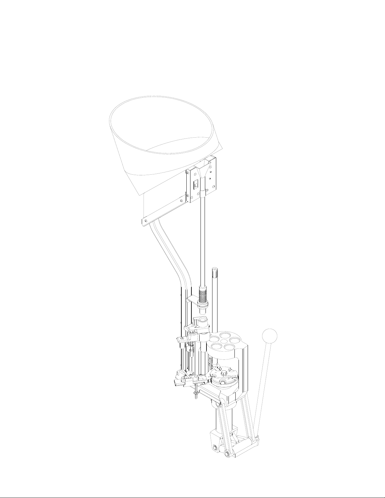
Step 1: Mounting the Lock-N-Load Auto Progressive with Case Feeder
Figure 1: AP with main bracket.
• Your work area should be well lit and have plenty of room for your reloading
accessories. Your Hornady Lock-N-Load AP should be mounted securely to the
edge of a solid level bench approximately 2 ¼” from the center of holes to the front
edge of the table when using the optional case feeder.
• While facing the bench and using the Main Bracket (#42) for a pattern, mark and
drill the mounting holes. Mount the press using (2) 5/16” bolts that are long enough
to secure the press to the bench with plenty of clearance for the nuts. (Due to
variations of benches we have chosen to not provide these items) We also
recommend using 5/16” flat washers at both ends of the bolts with lock washers on
the bottom side of the table. Washers are required on the two mounting bolts when
using the case feeder system.
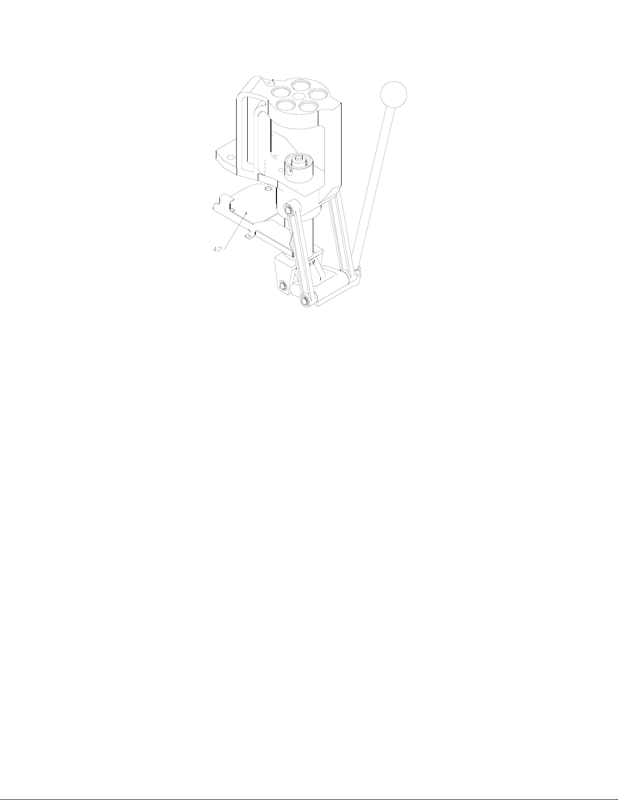
• Place the Main Bracket (#42) on the bench and verify that the mounting holes line
up with the holes. Place the Bracket on the underside of the Press Frame. Place one
of the 5/16 bolts through the mounting hole from the top. Place the press and bracket
on the bench, and run the bolt down through the appropriate hole and secure it to the
bench with a nut and washer assembly (finger tight is good for now). Align the
second hole, and using the second bolt, secure it to the bench. Operate the press; to
make sure that the bench does not interfere with it’s operation. If everything is
functioning proper, tighten the nuts on the bolts to finish securing the press and
mounting plate to the bench.
See Figure 1 for details.
5
Page 6
Step 2: Changing the Sub-Plate.
(This step is necessary only if you are installing the case feeder to an existing
press, with a serial number lower than 07000.) The new Sub-Plate (Part
Number 398309) is sold separately. The new priming system (Part Number
095210) is also sold separately for presses with serial # prior to 07000.
• Raise the Eject Wire (#46) to move it out of the way.
• Use a 9/16” end wrench to remove the bolt holding down the shell plate and
remove the shell plate.
• Remove the case retainer spring.
• Remove the primer feed assembly.
• Unhook the extension spring from the primer slide and remove it from the Sub-
Plate (#44).
• Remove the primer slide from the Sub-Plate.
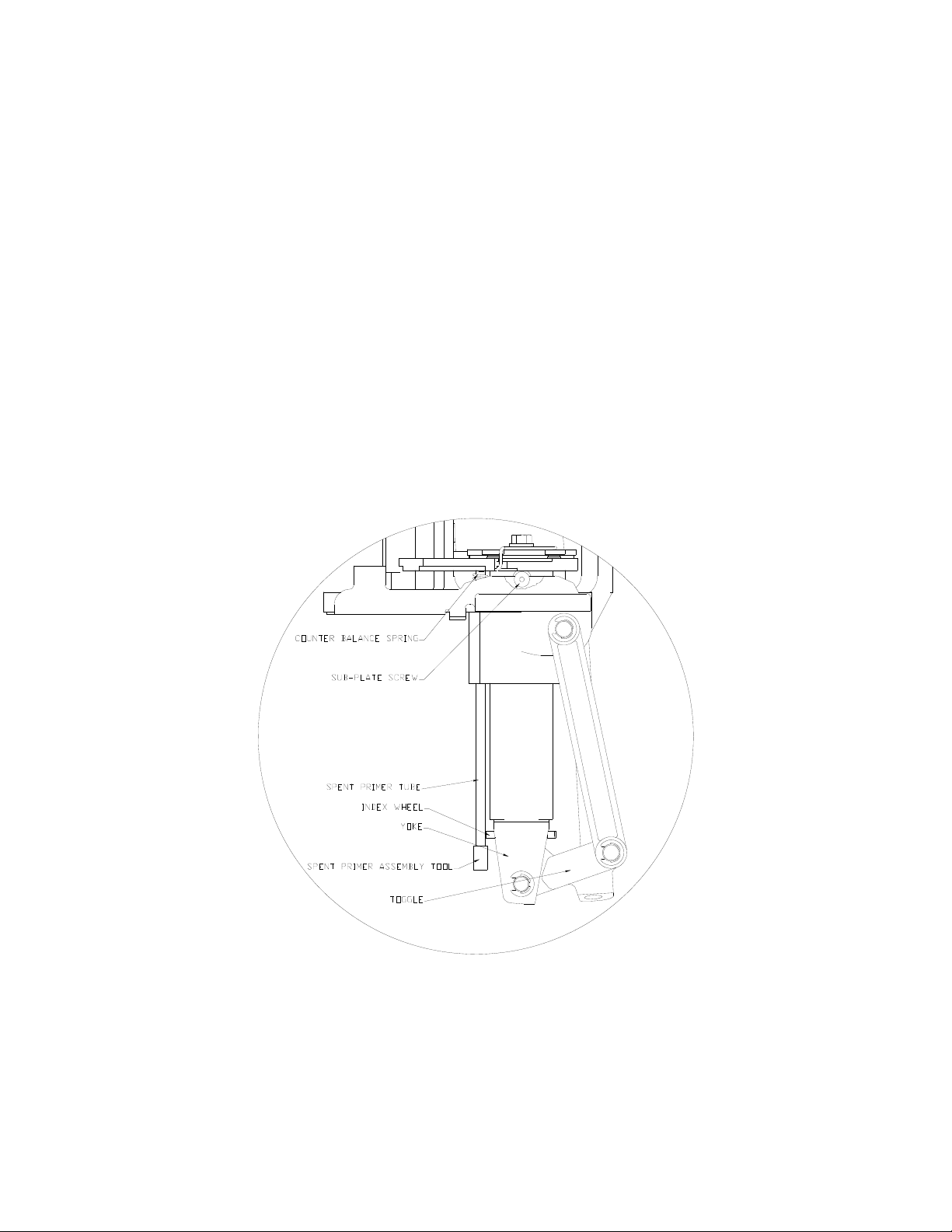
Figure 2: Spent primer tubes dismantle / assembly.
• Place the spent primer assembly tool in the bottom of the spent primer tube. Take
a pair of pliers or vise grips and clamp onto the spent primer tube approximately
¼” from the end and tap the pliers with a hammer to remove the spent primer
tube. Be careful not to lose the Counter Balance spring.
See Figure 2 for more details.
• Raise the ram to the top of the stroke and “Block” it into place
6
Page 7

• The Ram can be blocked into place by inserting the handle of a medium sized
screw driver between the “Toggle” and the “Yoke” near the pawls. Be careful not
to put extreme pressure on the Index wheel as you may damage it.
• Use a 5/32” Allen wrench to remove the two screws that secure the Sub-Plate
onto the ram.
• Remove the “Block” and lower the ram and remove the “Sub-Plate”.
• Install the new “Sub-Plate”, raise the ram and replace the “Block” before
installing the screws and tightening them very tight. (Be careful not to strip the
socket or damage the threads.)
• Once again, remove the “Block”, lower the ram and replace all parts in the reverse
order that you removed them.
The instructions thru Step 5 are for a Lock-N-Load Auto Progressive Frame without
the new machined bosses on the frame, serial # 07279 and later.
7
Page 8

Step 3: Assemble the square tubing brackets.
See Figure 3 for more details.
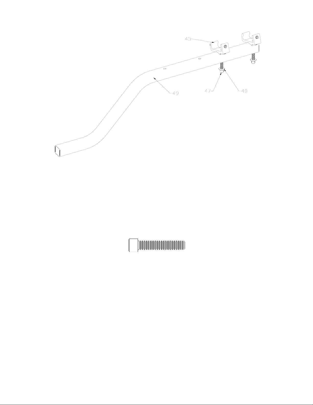
Figure 3: Square tubing bracket with set screws.
• Lay the two Brackets (#45) in front of you along with two 5/16-18 x 5/8 Cup Set
Screws (#35) and two 5/16-18 x 5/8 Cone Point Set Screws (#36).
• Place one Cone Point Set Screw (#36) into the side of the Square Tubing Bracket
(#45) until the point is just flush with the inside surface of the Bracket.
• Place one (#35) Cup Set Screw in the back of the Bracket until the cup point is
just flush with the inside of the Bracket.
• Repeat these steps for the second Bracket.
8
Page 9
Step 4: Mounting the square tubing brackets on to the square tubing.
See Figure 4 for more details.
Figure 4: Square tubing brackets with square tubing.
• Place the ¼” Flat Washers (#48) on the ¼-20 x 1 ¼” Socket Head Cap Screw
(SHCS) (#47).
• Place one SHCS thru the Square Tubing (#49) and into one of the Square Tubing
Brackets (#45) as shown and tighten finger tight.
• Repeat for the second Bracket.
¼-20 1 ¼” Cap Screw (Full Size)
9
Page 10

Step 5: Assemble the square tubing and brackets to the frame of the AP Press.
(This step is a preliminary adjustment and will be completed later in the assembly.)
See Figure 5 for more details.
Figure 5: Square tubing brackets to the frame.
• While standing to the left side of the press, (your left), hook the v-section of
bracket to the rib on the corner of the frame.
• Rotate the square tubing with the brackets counter clockwise (CCW) around
the corner of the press. Make sure that the tube rests on the tab of the
mounting bracket.
• Tighten the two (Cone Point) set screws (#36) until about half of the angled
point is past the corner of the rib on the press.
• Tighten the two (Cup Point) set screws (#35) until the square tubing assembly
is secure.
• Finish by tightening the screws (#47) on the Square tubing and bracket
assembly.
• The back of the square tubing should be parallel to the back edge of the frame.
If it is not, you will need to readjust it using the set screws.
• The assembly can be rotated clockwise by loosening the Cone Point screws
(#36) and tightening the Cup Points (#35), and visa versa to rotate it Counter
Clockwise. Complete the installation by tightening the Cup Point Set Screws
(#35).
10
Page 11

Step 6: Assemble the square tubing to the frame of the AP Press.
(For serial numbers beyond 07279.)
Figure 6: Square tubing to the frame.
• Place the ¼” Flat Washers (#48) on the ¼-20 x 1 ¼” Socket Head Cap Screw
(SHCS) (#47).
• Place one SHCS thru the Square Tubing (#49) and thread into the Frame.
• Repeat for the second Bracket.
• Tighten both screws down using a 3/16” Allen wrench.
¼-20 1 ¼” Cap Screw (Full Size)
11
Page 12

Step 7: Adding the case slide on to the sub-plate.
See Figure 7b for more details.
Figure 7a: Case slide assembly.
• While holding the case slide (#38) upside down in one hand, pull the
cardboard packaging rearward till the front edge bi-sects the foot at the front
of the slide.
See Figure 7a for more details.
Figure 7b: Case slide and sub-plate assembly.
• Turn the Case Slide (#38) right side up and start the slide onto the rail of the
sub-plate. While holding the end of the cardboard, push the slide onto the rail.
You may need to push up on the bottom of the cardboard while you are
pushing it on the sub-plate.
12
Page 13

• If now or anytime in the future the guide and spring come out of the slide,
they can be assembled by placing the spring in the relief of the slide and
hooking the relief of the guide onto the end of the spring. Slide the guide
forward and compress the spring until the guide fits into the pocket. You may
need to hold the “guide and spring” into the Slide with your finger as you
slide the assembly back onto the “Sub-Plate.”
13
Page 14

Step 8: Inserting the cam wire into the assembly.
See figure 8 for more details.
Figure 8: Assembly of cam wire.
• Raise the ram to the top of the stroke.
• Screw one #10-32 Hex Nut (#41) on to the Cam Wire (#43) approximately 1”
from the end.
• Place one of the #10 Flat Washers (#67) onto the Cam Wire (#43).
• From the bottom of the Sub-Plate (#44), slide the non threaded end of the
Cam Wire (#43) through the slot of the Sub-Plate (#44) and through the Case
Slide (#38).
• Insert the threaded end of the Cam Wire through the hole of the tab on the
Main Bracket (#42).
• Insert the other Flat Washer (#67) and Hex Nut (#41) onto the bottom of the
Cam Wire (#43) and tighten finger tight.
• Lower the ram.
14
Page 15

Step 9: Case escapement bracket assembly.
See Figure 9 for details.
Figure 9: Assembling Case escapement bracket on square tubing.
• Put a ¼” Flat Washer (#48) on the ¼-20 X 1 ½” Cap Screw (#70).
• Slide the Cap Screw (#70) thru the Square Tubing and thread the Hex Nut (#26),
on approximately the length of the nut.
• Slip the Case Escapement Body (#29) over the Cap Screw so the Hex Nut (#26) is
in the slot on the back of the Case Escapement Body. (#29)
• Slip the Cam Wire (#43) into the Cam Wire Support (#31).
• Tighten the Cap Screw (#70) while holding the Bracket level with the top of the
frame.
¼-20 x 1 ½” Cap Screw (Full Size)
15
Page 16

Step 10: Feed Tube Mounting Bracket to the square tubing.
See Figure 10 for more details.
Figure 10: Feed Tube Mounting Bracket with square tubing.
• Put a ¼” Flat Washer (#48) on a ¼-20 X 1 ½” Cap Screw (#70).
• Slide the Cap Screw (#70) thru the Square Tubing and place the Feed Tube
Mounting Bracket (#16) over the Cap Screw (#70), then insert the Hex Nut (#26)
on the Cap Screw and tighten. Make sure that the top of the Feed Tube Mounting
Bracket (#16) is level. Check with a small level if you are unsure.
¼-20 x 1 ½” Cap Screw (Full Size)
16
Page 17

Step 11: Determine which cartridge case you are going to be loading.
Chart 1 below shows what parts are needed for different size of cases.
Cases Item #'s Required Pg. 28 & 29 Notes
Small Pistol (9mm, 40 S&W, etc..)
Large Pistol (.357 Mag., .44 Mag, etc..)
Small Rifle (.223, 22 Hornet)
Large Rifle (243 Win., 45-70 Govt., etc..)
66,14,50,52,53 Cases smaller than .43" maximum diameters
13,15,22 Cases larger than .43" maximum diameters
66,14,50,18,51,52,53 Cases smaller than .43" maximum diameters
13,15,18,22 Cases larger than .43" maximum diameters
Chart 1: Cartridge Case change over chart.
If you find that some cases such as the 40 S&W are tight in the Feed Tube –Small (#14),
you may need to use the part of both the large and small feed tubes. For example, 40
S&W could use item numbers 13, 15, 19 and 53.
See figure 11 for more details on selecting the V-Block.
CASES DIAMETERS "X"V-BLOCK #V-BLOCKS P/N:
22 Hornet .27-.30 1 398292
9mm, .223 .37-.39 2 398293
44 Mag. .35-.38 3 398294
30-06 .42-.47 4 398295
458 Win. Mag. .46-.58 5 398296
10mm .41-.44 6 398297
Figure 11: V-Block selection chart.
17
Page 18

Step 12: Installing the V-Block onto the case slide.
Figure 12: Inserting the V-block.
• With the ram at the bottom of the stroke (idle position), set the V-Block (item
#60-#65) onto the Case Slide (#38).
• Place the #10-24 X 1/2 Cap Screw (#59) through the hole of the V-Block and
screw it into the Case Slide. Before you tighten the Cap Screw, push the V-Block
back into the Case Slide and snug the Cap Screw with your fingers.
18
Page 19

Step 13: Determine which shell plate is required for your application.
See Chart 2 below to help with this selection.
SHELL PLATE NO. 1
Item No. 392601
5.6x57 9.3x62
22/250 44 Auto Mag.
240 Wby. 45 ACP/WM 257 Wby. 6.5 Rem. Mag. 218 Bee 460 Wby. 30 M1 Carbine
243 Win. 260 Rem. 264 Win. Mag. 25/20 Win. 45/70 Govt. 32 ACP
244/6MM 270 Wby. 32/20 Win. 416 Wby.
6MM int.
6MM/284
6MM Br 219 Zi pper 300 H&H
250 Sav. 5.6x52R 300 Win. Mag. 30 Luger
25/06 22 Sav. HP 300 Wby. 9MM Luger 376 Steyr
257 Rbts. 25/35 Win. 300 Re. UI. Mag. 9x18 Makarov
25/284 30/30 Win. 308 Norma Mag. 38 Super Auto
6.5/06 30 Herrett 8MM Rem. Mag. 9x23
6.5 x 57 32 Win. Spl. 338 Win. Mag. 17 Rem.
270 Win. 8.15x46 R 340 Wby.
7x57 (7MM mau.) 357 Herrett 350 Rem. Mag.
7MM/08 375 Win. 358 Norma Mag. 38/40 Win. 221 Rem. 8x68 S
7MM Rem. BR 7x30 Waters 375 H&H 44/40 Win. 222 Rem. 7.5 Swiss 500 S&W
7x64 32/40 416 Rem. Mag. 222 Rem. Mag. 357/44 B&D
7MM Exp/280 458 Win.
284 Win.
300 Sav.
308 Win. 22 Hornet
30/06 22-K Hornet
7.7 Jap. 22 PPC
8MM Mau.
8MM /06
8x60 S 220 Swift 6MM PPC 30/40 Krag 380 Auto
35 Whelen 225 Winchester 7.62x39 6MM TCU 6x61 S&H
358 Win. 7MM Merrill 38/357/357 Max.
9.3x57
SHELL PLATE NO. 5 SHELL PLATE NO. 7
Item No. 392605 Item No. 392607
SHELL PLATE NO. 2
Item No. 392602
SHELL PLATE NO. 3
Item No. 392603
SHELL PLATE NO. 4
Item No. 392304
7MM Rem. Mag. 480/475 Linebaugh
7MM Wby.
450 Marlin
SHELL PLATE NO. 6
Item No. 392606
22 RCFM-Jet
256 Win. 303 British 7x47 Helm
SHELL PLATE NO. 8 Item No. 392626
Item No. 392608 SHELL PLATE NO. 15
SHELL PLATE NO. 9
Item No. 392609
SHELL PLATE NO. 10
Item No. 392610
10MM Auto 6MM/223
40 S&W 6x47 Rem.
SHELL PLATE NO. 11
Item No. 392611
SHELL PLATE NO. 14
Item No. 392614 Item No. 392636
33 Win.
338/378 Wby.
Item No. 392615 Item No. 392641
SHELL PLATE NO. 16
Item No. 392616 Item No. 392643
17/222
17/223 6.5x68
5.6x50 Mag. 44 Spl./44 Mag.
223 Rem.
6.5MM TCU 45 Long colt
7MM TCU 454 Casull
7MM/223 Ingram
204 Ruger
SHELL PLATE NO. 22
Item No. 392622
SHELL PLATE NO. 26
35 Remington
SHELL PLATE NO. 29
Item No. 392629
41 Mag.
SHELL PLATE NO. 30
Item No. 392630
SHELL PLATE NO. 32
Item No. 392632
SHELL PLATE NO. 35
Item No. 392635
SHELL PLATE NO. 36
32 S&W Long/Short/H&R
300 Win. Short Mag
SHELL PLATE NO. 40
Item No. 392640
50 AE
SHELL PLATE NO. 41
45 Schofeild
SHELL PLATE NO. 43
338 Lapua
SHELL PLATE NO. 44
Item No. 392644
Chart 2: Shell Plate selection chart.
Changing and installing the shell plate.
(Refer to the operations manual for the AP Press.)
19
Page 20

Step 14: Setting the timing of the cam wire.
Figure 13: Adjusting the V-block.
• Place a case of the proper size into the shell plate and manually push the Case
Slide (#38) and V-Block into the case. Loosen the Cap Screw (#59) and
continue to push the Case Slide into the case. Tighten the Cap Screw (#59)
with a 3/16” allen wrench.
See Figure 13 for more details.
Figure 14: Feeding a case.
• Raise the ram until the shell plate rotates and place a case (of the proper size)
in-front of the V-Block on the Sub-Plate. Lower the ram so the Case Slide
will advance the case into the shell plate.
20
Page 21

See Figure 13 for more details.
Figure 15: Cam rod adjustment.
If the “Cam Wire” is too high, it will:
1. Not allow the “Shell Plate” to advance. Loosen the upper nut several turns and
pull the wire down.
2. The case will hit the “Shell Plate” before it rotates. Again, loosen the upper nut
and move the wire down, but do this in small increments, as you are close.
If the wire is to low, it will:
1. Not advance the case into the shell plate. Loosen the Lower nut and tighten the
upper one to move the cam down.
Once the timing is correct, snug both nuts to the bracket and make sure the cam is
centered in the Slide. This can be adjusted manually by rotating it around the threaded
end a small amount. Tighten the nuts to complete the timing process. This timing setting
is adequate for all cartridges, and it should not be necessary to make future changes.
21
Page 22

Step 15: Assembling the feed tube end and pivot.
See Figure 15 for more details.
Figure 16: Pivot Assembly.
• If the maximum case diameter is larger than .43 you will need to use the large
tube (#22). If it is smaller, you will need the small tube (#53). Place the correct
one into the pivot block (#29).
• Place the torsion spring (#23) into the slot in the pivot block (#29), leaving the
long leg on the top side. The spring will only fit one way.
• Set the pivot (#19) on top of the pivot block. Make sure you line up the under cut
on the cam with the torsion spring. The leg of the torsion spring will fit into the
slot on the cam.
• When this fits together the pivot should fit on top of the pivot block. The dowel
pin in the cam will fit into the curved slot on the cam block.
• Then insert the shoulder bolt (#20) into the pivot and into the pivot block and
tighten with an allen wrench.
• Actuate the pivot by hand to make sure it will rotate properly.
• For small rifle cases place the pivot adapter bushing (#51) into the hole of the
pivot adapter. See pg. 25 for more details.
• Place the pivot adapter (#18) on top of the pivot for rifle cases (See pg. 25 for
more details).
22
Page 23

Step 16: Placing the Feed tube end on the assembly.
17a. 17b.
Figure 17: Setting the Feed tube end.
• Select the tube for your application (#15 or #50), see pages 25 and 26.
• Screw one lock ring on the tube.
• Place it thru the hole on the feed tube mounting bracket. Adjust the height of the
tube to have approximately 1/16” below the bottom of the tube to the case mouth.
(See Figure 16a for more details.) With some cases such as the 357 Mag. it may
be necessary to adjust the tube to where the case mouth sits up inside of the tube
approximately 3/16”. (See Figure 16b for more details.) These are both starting
points, and for your particular case, it may need to be adjusted a little differently.
(Long skinny cases, which are shorter than 1.50” long will not work with the
Pivot Adapter (#18). They may need to be supported at the mouth of the case by
the Feed Tubes (#15 or #50). This will allow the case to feed down the Drop
Tubes (#22 or #53) with out falling over and causing double or triple feeds.
• Screw on the other lock ring.
• Select the proper “Feed Tube” (#13 or #14) and insert it in the top of the “Feed
Tube End” (#15 or #50). If you select The Small Feed Tube (#14), you will have
to use the Plastic Feed Tube Small Bushing (#66), see pages 25 and 26.
(When feeding some cases (such as the 357 Mag.) you may notice that the base of
the case will not fall into the hole of the pivot every-time. The base will ride on the
radius of the pivot hole. You can operate the press with the cases doing this and
when the push rod (#24) starts to rotate the cam, the case will fall into the hole).
23
Page 24

Step 17: Selecting the case feed wheel for your application.
See Chart 3 for more details.
Small Pistol
Case Feed
Wheel
P/N: 095310 P/N: 095312 P/N: 095314 P/N: 095316
9mm 10mm Auto 7.62 X 39 6mm Rem. .284 Win. .356 Win. .300 Rem . Saum
9 X 21 .357 Mag. .17 Rem. 6.5mm Rem. Mag. .30 Rem. .358 Win. .300 WSM
.38 Super .357 Rem. Max. .218 Bee 6.5 X 55 Swedish Mauser .30-06 Springfild .375 H&H Mag. .300 Dakota
9 X 18 Makarov .38 Long Colt .222 Rem. / Rem Mag. 7mm Mauser (7 X 57) .30-30 Win. .375 Win. .300 Rem. Ultra Mag.
9mm Win Mag .38 Short Colt .223 Rem (5.56mm) 7mm Rem. Mag. .30-40 Krag .38-55 W i n. .338 Rem. Ultra Mag.
.30 Luger .38 S&W .30 Carbine 7mm W BY Mag. .300 H&H Mag. .416 Rem. Mag. . 340 WBY Mag.
32 ACP . 38 S pl. .32-20 Win. 7mm-08 Rem . .300 Savage .416 Rigby .378 WBY Mag.
.32 H&R Mag .41 Rem. Mag. .351 Win Self Loading 7-30 Waters .300 WBY Mag. .444 Marlin .404 Jeffery
.32 Long Colt .44 Spl/Mag. .25-20 Win. 8mm Mauser (8 X 57) .300 Win. Mag. . 45-70 Govt. .460 WBY Mag.
.32 Short Colt .45 A CP 8mm Rem. Mag. .303 British .458 Win. Mag. 500 S&W
.32 S&W .45 Aut o Rim. .22-250 .303 Savage .458 Lott
.32 S&W Long . 45 Colt .220 Swift .307 Win. .450 Marlin
.380 Auto .45 Win. Mag. .225 Win. .308 Win. .376 Steyr
.22 Hornet .454 Casull .243 Win. .32 Rem. .405 Win.
40 S & W 9 X 25 .25-06 .32 Win. Spl. .240 WBY Mag.
Large Pistol
Case Feed
Wheel
.22 Rem. Jet .25-35 Win. .32-40 Win. .257 WBY Mag.
.256 Win. Mag. .250 Savage .338 Win. Mag. .270 WBY Mag.
.475 Linebaugh .257 Roberts .348 W i n. .270 WSM
.480 Ruger .264 Win. Mag. .35 Rem. 7mm Rem Saum
.38-40 Win. .270 Win. .35 Whelen 7mm STW
.44-40 Win. .280 Rem. .350 Rem. 7mm Rem. Ultra Mag.
Small Rifle Case
Feed Wheel
Large Rifle Case Feed
Wheel Large Rifle Cont. Large Rifle Cont. Large Rifle Cont.
Chart 3: Case feed wheel selection chart.
24
Page 25

Figure 18: Case feed bowl door adjustment.
• Select the Case Feed Plate (item #54-57) for your application and place it on the
motor shaft. The clutch on the plate will slip onto the motor shaft fitting flush to
the bottom of the Case Feed Bowl (#1).
• Place the O-Ring onto the Feed Tube Large (#13) approximately 2” from one end.
The O-Ring when pushed down on top of the Feed Tube End (#15) will hold the
feed tube into the funnel on the case feed bowl.
• Set the Case Feed Bowl (#1) on top of the Square Tubing (#49) while inserting
the Feed Tube (#13 or #14) into the Case Feed Funnel Assembly (#8) and plug it
into a power outlet.
• If you are loading rifle cartridges you will need to adjust the Case Feed Door
(#37).
• Loosen the ¼” Button Head Cap Screw (#68) and slide the Case Feed Door
Adjustment (#37) so the opening is approximately ¾ the length of the case. This
is a preliminary setting. Place a hand-full of cases into the Case Feed Bowl (#1).
• Turn the motor on and observe to see if the cases will fall base first. If they do
not, readjust the Case Feed Bowl Door Adjustment (#37) until they do with out
hanging up or getting caught.
• Re-tighten the ¼” Button Head Cap Screw (#68).
• To load pistol cases, completely open the Case Feed Door Adjustment.
See figure 17 for more details.
25
Page 26

Step 18: Adjusting the push rod.
Figure 19: Push Rod adjustment.
• Screw the Push Rod Nut (#33) and the Push Rod Lower (#34) onto the Push Rod
(#24) until the Push Rod Lower (#34) bottoms out on the thread.
• Place a case in the hole of the Pivot (#19) and the Escapement Height adjuster
(#18) (if required).
• Raise the ram to the top of the stroke slowly, so the Case Slide (#38) will actuate
the Push Rod (#24) and Pivot (#19). The Pivot (#19) should rotate far enough to
drop a case down the Feed tube (#13-14). If it does not, lower the ram just far
enough to take the pressure off of the Push rod (#24). Screw the Push Rod Lower
(#34) down a couple of turns and retry. When the Pivot (#19) is dropping a case
thru the Feed Tube, screw the Push Rod Nut (#33) down on top of the Push Rod
Lower (#34) and tighten with your fingers.
• If the case is falling on top of the V-Block, refer to step Step 5.
Single case operation
(To feed cases singly without using the case feeder.)
• Remove the Push Rod Lower (#34).
This will allow the press to be cycled without dropping cases.
Fail-safe mechanism
The Cam Wire (#43) has a fail-safe mechanism at its top (Cam Wire Support #31). The
Cam Wire Support (#31) holds the Cam Wire (#43) in place. If a malfunction occurs, the
Cam Wire (#43) is able to snap out of the support to prevent damage to the Cam Wire.
26
Page 27

Maintenance of the Lock-N-Load A/P Case Feeder
g
g
j
g
As with all equipment, proper and routine maintenance will provide smooth operation
and a longer life for your reloading press and Case Feeder. At the end of each reloading
session, wipe off all spilled powder, any dirt, etc., from the press. Check all moving parts
for dirt or spilled powder and remove with a clean rag.
Tips for trouble-Free operation
Problems Solutions Step
Cases are hitting the back corner
of the shell plate when feeding
into the shell plate.
Slow timing down or Readjust V-Block location 13
Cases are not feeding into the
shell plate far enou
h
Cases are tipping when going into
the shellplate
Cases are falling on top of the VBlock
Drop tube is tight against the AP
Frame; will not allow changing of
tubes
Cases are falling mout h first out
of the bowl
Cases are getting caught in the
open hole on the bowl
The shell plate is hitting the VBlock when it's rotatin
Chart 4: Trouble free operation.
Speed timing up or
Using the wrong V-Block 13
Re-adjust V-Block
location 13
Re-adjust the Bracket,
Square Tubing 5
Re-adjust the Bracket,
Square Tubin
5
Close the door
ad
ustment 16
Open the door
adjustment 16
Lower the Cam Wire 13
27
Page 28

Producti
Producti
Bill of Materials
on Part
Item No.
Number Qty.
1 398327 1 CASE FEED BOWL 37 398285 1 CASE FEED DOOR ADJUSTMENT
2 398313 4
3 398374 8
4 398415 8
5 398326 1 MOTOR HOUSING
6 398375 2
7 398333 1 MICRO SWITCH
8 398369 1
9 398376 1
10 398332 2
11 398331 1 MOTOR
12 398328 1 MOTOR COVER
13 398320 1 FEED TUBE - LARGE 49 398284 1 CASE FEED STAND
14 398321 1 FEED TUBE - SMALL 50 398304 1 FEED TUBE END - SMALL
15 398303 1 FEED TUBE END - LARGE 51 398300 1 PIVOT ADAPTER BUSHING
16 398286 1 FEED TUBE MOUNTING BRACKET 52 398301 1
17 396440 2 LOCK RING 53 398306 1 DROP TUBE - SMALL
18 398298 1 PIVOT ADAPTER 54* O95310 CASE FEED PLATE- SMALL PISTOL
19 398290 1 PIVOT 55* O95312 CASE FEED PLATE - LARGE PISTOL
20 398310 1 1/4-3/4 SHOULDER BOLT 56* O95314 CASE FEED PLATE - SMALL RIFLE
21 398311 1 3/0 X 3/4 TAPER PIN
22 398305 1 DROP TUBE - LARGE 58 O59100
23 398288 1 SPRING, TORSION 59 392338 1 10-24 X 1/2 SHCS
24 398317 1 PUSH ROD
25 398371 1
26 390178 2 1/4-20 HEX HEAD NUT 62 398294 1 V-BLOCK #3
27 398349 1 PUSH ROD BUSHING
28 398364 1
29 398344 1 PIVOT BODY
30 398363 1
31 398343 1 CAM WIRE SUPPORT
32 398425 1 E CLIP 1/4 68 390410 1
33 398373 1
34 398372 1
35 398314 2 5/16 -18 X 5/8 SET SCREW CUP 71 398416 1 O-RING 7/8 OD, 11/16 ID
36 398315 2 5/16 -18 X 5/8 SET SCREW CONE POINT (45 DEG.) 72 398550 6 RIVET POLY BLACK
10-32 x 3/4 FHSCS
10-24 "U" Nut
#8 x 1/2 SHEET METAL SCREW PAN HEAD PHILIPS
4-40 HEX HEAD LOCK NUT
CASE FEED FUNNEL ASSEMBLY
4-40 X 5/8 BHSCS
ROCKER SWITCH
PUSH ROD TIP
10 X 1/2 SHEET METAL SCREW PAN HEAD PHILIPS
PUSH ROD SPRING
PUSH ROD NUT
PUSH ROD LOWER
Description Item No.
38 398291 1 CASE SLIDE
39 398307 1 CASE SLIDE ROD GUIDE
40 398308 1
41 392011 2 10-32 HEX HEAD NUT
42 398289 1 MAIN BRACKET
43 398299 1 CAM WIRE
44 398309R 1 SUB-PLATE (ON PRESS OR WITH RETROFIT KIT)
45 398287 2 BRACKET, SQ. TUBING
46 398345 1 EJECT WIRE (ON SUB-PLATE #44)
47 398312 2 1/4-20 X 1.25 SHCS
48 390128 4 1/4 FLAT WASHER ZINC PLATED
57* O95316 CASE FEED PLATE - LARGE RIFEL
60 398293 1 V-BLOCK #1
61 398297 1 V-BLOCK #2
63 398292 1 V-BLOCK #4
64 398295 1 V-BLOCK #5
65 398296 1 V-BLOCK #6
66 398324 1 PLASTIC FEED TUBE SMALL BUSHING
67 390651 2 3/16" FLAT WASHER SAE
69 398370 1
70 398388 2 1/4-20 X 1.50 SHCS
on Part
Number Qty.
Description
CASE SLIDE ROD GUIDE SPRING
PIVOT BUSHING
AP PRESS
10-24 x 1/4 BHSCS
CASE FEED BOWL BUSHING
Chart 5: Bill of Materials.
(“*” Sold Separately) (“Italics” Pre Assembled)
28
Page 29

29
Page 30

(780308, Original, 09/02/04)
30
 Loading...