

Page 1
HORNADY
366 AUTO
AUTOMATIC SHOTSHELL RELOADER
OPERATION MANUAL
Page 2

Table of Contents
Steps: Page
Overview......................................................................................3
Standard Loads and Bushings......................................................3
Setting up your 366 Auto.............................................................4
Function and Adjustment.............................................................5
1. Resize and De-Prime (Station 1A) ........................................6
2. De-Prime Only (Station 1) ....................................................7
3. Prime (Station 2) ...................................................................8
4. Powder Drop (Station 3)........................................................9
5. Wad Seating (Station 4) ........................................................10
6. Shot Drop (Station 5) ............................................................11
7. Crimp Starter (Station 6) .......................................................12
8. Crimp (Station 7)...................................................................13
9. Crimp Taper (Station 8) ........................................................14
Adjustment of Auto Advance ......................................................15
Trouble Shooting .........................................................................16
Converting to another Gauge.......................................................19
List of Illustrations
Figures:
1. Function and Adjustment......................................................5
2. Resize and De-Prime.............................................................6
3. De-Prime...............................................................................7
4. Prime.....................................................................................8
5. Powder Drop .........................................................................9
6. Wad Seating..........................................................................10
7. Shot Drop..............................................................................11
8. Crimp Start............................................................................12
9. Crimp ....................................................................................13
10. Taper Crimp.........................................................................14
11. Adjustment of Auto Advanced ............................................15
12. Exploded View.....................................................................23
List of Charts
Charts:
1. Powder Bushings ...................................................................20
2. Bill of Materials .....................................................................21
2
Page 3

SHOTSHELL RELOADER INSTRUCTIONS
To help you load completely satisfactory ammunition the first time you operate your 366 Auto,
these instructions have detailed steps of operation and adjustment to help in avoiding problems.
To begin loading shot shells, you will need powder, shot, primers and wads, in addition to empty
hulls. Before purchasing any of these components, first note what charge the standard bushing
furnished with your loader will throw by weighing your charge. Listed on the label on the outside
of the carton is a powder bushing and shot bushing number which is referenced to a powder weight
and brand, as well as shot amount and type.
STANDARD LOADS AND BUSHINGS
If the referenced powder in not available, refer to the recommended load chart furnished with this
loader. This chart will show the other powder weights and brands it will dispense. It is not to be
taken for a reloading manual. Loading data from the major powder manufactures is furnished,
when available, to help you in getting started. Unless you have experience in shot shell reloading,
ask your dealer to help you pick the best starting combination, or contact Hornady’s Reloading
Advisory Center.
IMPORTANT: Never mix powders or use unidentified powder. Do not use smokeless powder
in old firearms until the firearm is certified safe. Do not exceed recommended loads.
Your 366 Auto is a precision machine. It is the only loader to feature full-length resizing with
each stroke, automatic primer feed, swing-out wad guide, three stage crimping with taper-loc for
factory tapered crimp, automatic advance to the next station and automatic ejection with the option
of a gas assisted automatic advance.
This press should give you many years of enjoyable, trouble-free service. Any problems that you
have can generally be corrected by slight adjustments of the dies and punches in each station. If
you are unable to correct the problem, please write us or call:
Hornady Mfg. Co.
PO Box 1848
Grand Island, NE 68802-1848
800-338-3220
DO NOT RETURN THE LOADER TO YOUR DEALER.
3
Page 4

SETTING UP YOUR 366 AUTO
Mount your 366 Auto securely toward the front of a sturdy bench. All operations of the press are
to a full stop, so the operating handle must clear the bench when in the down position. Since the
shells are ejected down a chute, out the back of the loader, you may want to set your loader up on
riser blocks (010060) to provide access to the completed shells. An alternate method to catch
finished shells would be to cut a hole in the bench and place a box underneath.
1. Before filling the shot and powder hoppers, turn the measure assembly upside down and
carefully push the charge bar out and check the powder and shot bushing numbers.
2. Your loader was furnished with standard bushings, 12 GA. 1 ⅛ oz. #7 ½ shot, 468 Powder
Bushing; 20GA. ⅞ oz. #9 shot, 393 Powder Bushing; 28 GA. ¾ oz. #9 shot, 303 Powder
Bushing; 410 GA. ½ oz. #9 shot, 291 Powder Bushing but double check to insure you will
dispense the correct weight of powder and shot.
3. While the charge bar is removed or pushed back, check that the measure casting seals
(rubber washers) are in the recess in the measure casting.
4. Reinstall the bushings and push the charge bar back in place. If the powder slide should
drop out of the measure assembly, do not disassemble the measure plate.
5. Replace the powder slide by pressing it in from the side against the detent spring, pull
spring back and fit into slot.
6. Reinstall the measure assembly by tilting the casting as you slip the measure plate and shot
rotor spring under the hold down washer, and the charge bar into the slot of the charge bar
cam.
7. Secure assembly in position with measure attaching bolt.
8. Install the primer tube in the die head casting and fill the primer tray according to
instructions furnished with it. Do not fill the tube at this time.
9. Check the individual stations of the loader for alignment to make sure nothing has loosened
during shipping. Shut off the powder slide (push in) and the shot rotor (pull forward) while
checking each station.
READ THIS SECTION BEFORE ATTEMPTING TO LOAD AMMUNITION!
4
Page 5
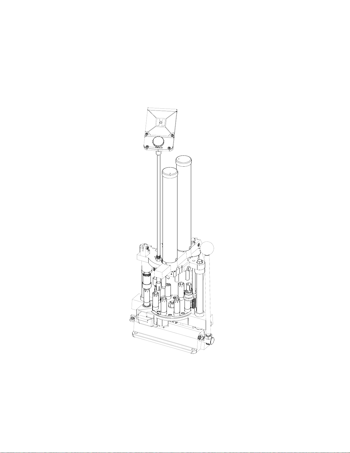
FUNCTION AND ADJUSTMENT
Fig. 1: Function and Adjustment
The following is a detailed description of the operation and adjustment of the 366 Auto
Reloading Press. This press has been pre-adjusted at the factory for Remington STS cases, but
every person has a preference about how the finished product should look, so some changes might
be necessary. The reloader should begin by advancing a single shell through each station to
familiarize himself with the operation and adjustment of each position. The illustrated
discussion which follows shows the 366 with all eight stations filled. Since your first shell will be
the only one in the loader, be sure the shot and powder slides are off at the beginning of the
sequence.
Sort your shot shells by brand and type. Refer to the loading manuals provided for
recommended loads for your shot shells.
5
Page 6
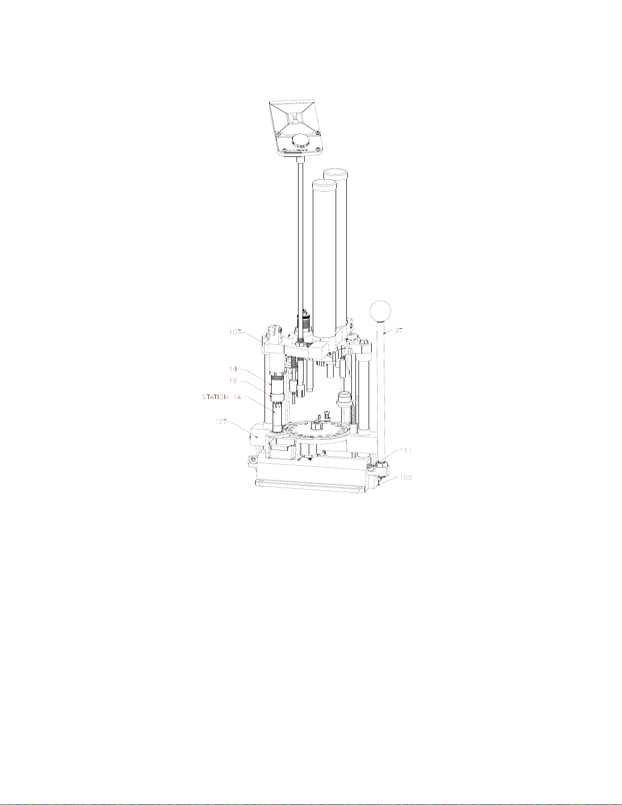
Step 1: STATION 1A (Resize and Deprime)
Fig. 2: Resize and De-Prime
Place an empty shell in Station 1A, making sure the deprime punch enters the case mouth
and the shell is reasonably centered under the size die (#14). Pull the operating handle (#37) to the
bottom of the stroke. Make sure nothing interferes with the handle reaching bottom. When the
operating handle is pulled, the platen casting (#107) rises until the eccentric arm stop (#111)
contacts the base casting (#100). At this point, the shell should be completely enclosed in the size
die (#14) and there should be no gap between the size die ring cap (#19) and the platen casting
(#107). When the handle (#37) is returned, the de-prime punch guide (#8) pushes the case from the
die. The expander (#8) is threaded on the deprime bolt (#62) which is forced down by the clevis
link (#13) attached to the head casting (#7). The size die (#14) should size the brass head and rim
to permit the chambering of that shell in any firearm. Properly adjusted, the size die (#14) just
contacts the platen casting (#107). All other dies are set from this adjustment point, but are
designed with all stations full. Interference with the handle (#37) can cause light powder charges
or primers not seated properly. The size die (#14) and the size die ring cap (#19) must be kept tight
at all times.
6
Page 7
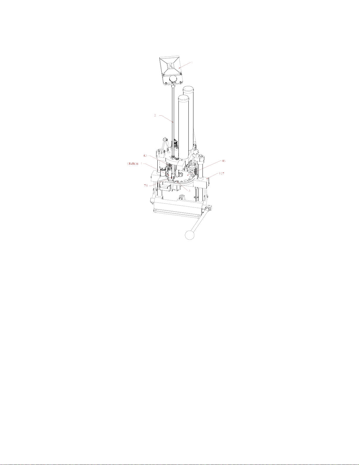
Step 2: STATION ONE (De-prime Only)
Fig. 3: De-Prime
Insert the case in station.
1. Normally, at this time, we would fill the primer tube (#2), but since we are working with a
single shell, drop only one primer from the tray (#1) into the primer tube (#2). Now pull the
handle (#37). As the handle (#37) makes a complete cycle, the shell will automatically
advance to the next station also dropping the primer into the hole in the primer seat pad
(#3). Some individuals may wish to bypass Station 1A but a shell must be in place in
Station 1 before pulling the handle (#37). The shell automatically advances on the return
stroke and if Station 1 is empty, there will be a gap in the reloading sequence.
Primer Drop: Until you are more familiar with your reloader, always return the handle
smoothly and, at first slowly. The primer is dropped when the shell plate (#45) contacts the
plastic primer drop stop unit (#78) at the bottom of the down stroke, and spreads the fingers of
this unit, allowing the primer to slip into the hole provided in the shell plate (#45). At this
point, make sure that the metal portion of the primer feed body (#42) does not make contact
with the shell plate. Such contact will turn a burr on the inside and prevent primers from
falling.
The primer seat pad (#3) is notched to improve the primer drop, but the primer only falls at
the speed of gravity, so the handle (#37) must not be raised too rapidly, or the primer could be
jammed between the shell plate (#45) and the platen casting (#107). Therefore, operate the
handle smoothly, and only as fast as primers will reliably drop into the primer seater pad (#3).
7
Page 8

Step 3: STATION TW0 (Prime)
Fig. 4: Prime
Pull the handle (#37) through a complete stroke. The primer seating punch (#20) or the
optional spring loaded primer seater punch (010051) will enter the case and push the case
down, over the primer in the primer seating pad (#3). On the return stroke, the primer seating
pad (#3) will push the case back up into position and the shell plate (#45) will advance to the
next position. Before continuing the loading sequence, remove the primed case, to inspect the
primer seat depth. To remove, lift the pawl (#94) from the indexing position and rotate the
shell plate (#45) back to station one and inspect the seated primer. The primer should be flush
with the case head. If the primer is not fully seated, the primer seater punch (#20) must be
adjusted. Different brands of cases have different base wad heights. Replace the case in
position at Station Two. Loosen the primer punch lock nut (#23). Pull the handle (#37) down,
and steadily lower the primer seater punch until you feel the punch start to interfere with the
handle (#37). The primer seating punch (#20) should then be backed up just enough to
eliminate any interference. Your loader was factory set to load the low base wad of the modern
compression formed type cases and may not need any adjustment. The primer seater pad notch
should be on your right as you face the loader.
8
Page 9

Step 4: STATION THREE (Drop Powder)
Fig. 5: Powder Drop
Before pulling the handle (#37), pull the powder slide (#69) toward you. The spring (#71)
will lock the slide in place in the second slot of powder slide (#69). The powder drop is now
on. During the stroke, the powder bushing will advance to the Powder Drop station.
Normally, we would leave the powder slide on, but since we are taking one shell through each
step, push the powder slide back and shut off the powder. (Do this before pulling the handle
again.)
There is no adjustment to the powder drop, but the drop tube should be kept clean and dry and
must be able to float freely in the head casting. To clean the drop tube, use brake cleaner to
remove all oils.
9
Page 10

Step 5: STATION FOUR (Wad Seating)
Fig. 6: Wad Seating
Insert a wad in the wad guide (#106A). Pull the operating handle (#37) through a complete
stroke. When the handle (#37) is pulled, the spring (#106B) around the wad guide rod (#105)
turns the wad guide bracket (#101) to align the wad with the case. The unit then rises until the
wad is stopped with the platen casting (#107) by the wad ram (#48). The case continues
upward until the spring fingers (#77) have entered the case mouth, and then pushes the wad
guide (#101) upward until the wad is seated in the case. The spring fingers (#77) have enough
resistance to prevent the wad from going through until the spring fingers (#77) are in the case.
At the completion of the return stroke, the wad guide bracket (#101) will swing forward for the
next wad to be inserted. The wad guide bracket should have 1/8” clearance above the
shells. The empty shells vary in length so a closer setting would not be beneficial. Be sure the
wad seating ram (#48) is set high enough for the wad to swing into position with out being
folded by early contact with the wad seating ram (#48). Wad pressure is adjusted by raising
or lowering the wad seating ram (#48). Most one-piece plastic wads today will self-adjust
when the shell is crimped. Generally, the wad should be seated to allow 5/8” clearance
between the case mouth and the shot.
10
Page 11

Step 6: STATION FIVE (Shot Drop)
Fig. 7: Shot Drop
Before pulling the handle (#37), rotate the shot shut-off (#70) backward, turning on the
shot. Now, lower the handle (#37). The shot drop tube (#47) enters the case mouth and then
both case and shot drop tube (#47) rise together to the top of the stroke. In this fashion, all the
shot enters the case without being spilled. No adjustment of this station is possible. Upon
completion of the stroke, the shells will advance to the next station. Normally, we would leave
the shot drop on, but since we are taking a single shell through the sequence, rotate the shot
rotor (#70) forward to shut off the shot.
11
Page 12

Step 7: STATION SIX (Crimp Start)
Fig. 8: Crimp Start
As you lower the handle (#37), the shell at Station Six enters the crimp starter (#82). The
plastic body has ridges on the inside to align with the old crimp and restart the folds. The
outside of each crimp starter (#82) has a ridge corresponding with the inside, so if manual
alignment is necessary with damaged crimps, follow these ridges. A hole in the case mouth of
¼” should be left when the shell completes this station. Hornady loaders come with eight
point crimp starter installed, but if you are using another crimp, substitute with either smooth
for paper or six point plastic, included with your loader. The plastic starter unit unthreads from
the rod (#65) extending through the main body. The amount of “start” may be adjusted, but too
much can cause the wall of the case to collapse, producing a defective shell.
12
Page 13

Step 8: STATION SEVEN (Crimp)
Fig. 9: Crimp
As you pull the handle (#37), the shell in Station Seven will enter the crimp die (#59). The
shell will contact the inside of the die and raise the die body (#59) as it goes up. It will then
contact the crimp plunger (#58) and the crimp will be closed. On the return stroke, the shell
will be pulled from the crimp plunger (#58) but the crimp die (#59) will keep pressure on the
case to retain the proper shape. Since different manufactures’ cases have varying types of
construction, different settings are required for best results. The two-stage die enables the user
to create a reloaded round that has approximately the same tapered mouth as a factory shell.
There are two adjustments to the crimp die assembly (#57, #58, and #59); the larger outer
position adjusts the die body (#59), the threaded bolt through the center of the die adjusts the
crimp plunger (#58). To adjust the die, refer to the number of threads exposed above the large
die body locking nut (#15) as reference points for each brand of case. For Winchester AA type
shells, ten to ten and one half threads should remain above the locking ring (#15); for
Remington Blue Magic and Federal Gold Metal Cases, eleven to thirteen threads should be
exposed. These measurements are approximate and may need adjustment up or down,
depending on the plastic and components, but should be correct in most situations. Before
adjusting the crimp the crimp die (#59), the crimp plunger (#58) should be raised a few turns
by loosening lock nut (#15) and turning the crimp die bushing (#57) clock wise. Then, make
the necessary die body (#59) adjustments, and follow by crimping the case. At this point, the
case mouth will not be closed. Lower the crimp plunger (#58) in small increments, each time
recrimping the shell until the final desired crimp depth is obtained. The crimp depth is up to
you, but excessive depth shortens case life, while a crimp that is too shallow will not yield
uniform velocity or good patterns. A good practice is to keep a factory round on hand for
reference
13
Page 14

Step 9: STATION EIGHT (Taper Crimp)
Fig. 10: Taper Crimp
The taper crimp is a smooth crimp starter (#82) and will taper the finished case better than
factory loads. As the shell at Station Eight enters the taper crimp die (#59), the mouth of the
shell will be “rolled.” On the return stroke, the shells advance, but the shell in Station Eight
contacts a cam in the platen casting (#107), moves to the left, and drops through a hole in the
platen casting (#107) down the chute (#108) to the back.
Adjustment of the taper crimp (#82) is done by loosening the lock nut (#29) and raising or
lowering the taper crimp starter (#82) to obtain the desired taper on the case mouth.
At this point in a normal reloading sequence, you would have a completed shell at each
station. To begin reloading, go back to the beginning and follow instructions for Step 1
and Step 2, but this time fill the primer tube (#2) when you insert a shell in Station One.
As the shells advance around the loader, remember to turn on the powder and shot when
the shells advance to the positions, and to reinsert a shell at Station One and a wad in the
wad guide after each pull of the handle. You can continue the sequence until all your
empty shells have been reloaded but always remember to check the powder and shot
hoppers (#80) and make sure a primer drops on each stroke. If you refill the primers,
shot and powder after each 100 rounds, you will never load shells without components.
14
Page 15

ADJUSTMENT OF AUTO ADVANCE
Fig. 11: Adjustment of Auto Advance
When the operating handle (#37) is pulled all the way up, a spring (#98) swings the pivot
arm (#85) and the advance pawl (#94) to your right. The hook of the pawl rides in the gap
between the shell plate (#45) and the shell plate ring (#110). On the return stroke, the roller on
the base casting (#100) contacts the curve on the pivot arm (#85) and the entire unit is cammed
toward the left, advancing the shells to the next position. The cam bearing (#12) is mounted
off-center on the bolt (#25) so when it is turned, the cam bearing is shifted right or left. If an
adjustment is necessary, loosen the lock nut (#28) and turn the eccentric bolt (#93) with a
screwdriver. It is necessary to hold the eccentric bolt (#93) with the screwdriver when
tightening the nut (#28).
15
Page 16

TROUBLESHOOTING
Handle will not come to bottom of stroke
Do not force the handle (#37). If you meet with any resistance, shut off the shot and powder
and slowly return the handle (#37) back to normal while unlatching the rotating pawl (#94).
1. Check to see the loader is mounted near the front of the bench, allowing the handle (#37) to
come completely down.
2. Check to see if the size die body (#14) adjustment has changed or if the size die ring cap
(#19) has loosened.
3. Check that the de-prime punch guide (#8) is threaded all the way up on the size die ejector
bolt (#62).
4. Check to see that you are not seating a second primer on top of an already primed case.
5. Check the primer seater punch (#20) to see if it is adjusted too low. Readjust to seat the
primer when the handle (#37) is depressed.
6. Check to see that you aren’t trying to seat a second wad on top of another and the wad
entered the shell correctly.
7. Check to see that shells are in alignment and the correct shell is in each station.
8. Check for an obstruction inside the shell which would prevent you from depriming or
repriming the case.
9. Check to see that you aren’t trying to load a high base wad shell when you are set up for
low base wads.
10. Check to see if a loaded shell has rolled underneath one of the eccentric arms.
Handle will not turn to normal position on backstroke.
DO NOT FORCE THE HANDLE. Shut off the powder and shot and unlatch the rotating
pawl (#94).
1. Check the clevis link (#13) to see if it is bent and hanging up on the size die eject bolt
(#62). Replace if necessary.
2. Check the primer seater station to see that the primer was fully seated. If not, lower the
primer seater punch (#20).
3. Check to see that the wad is being fully seated and not pulling back up into the wad guide
bracket (#101).
16
Page 17

4. Check the wad guide bracket (#101) to see that the wad guide return spring (#106B) is
attached and that the bracket is fastened to the wad guide rod (#105).
5. Check the charge bar cam (#9) adjustment to see that it hasn’t slipped.
6. Check for an obstruction, spilled shot, etc., between the shell plate ring (#110) and the
platen casting (#107). If there is, you may need to rotate the pawl (#94) clock wise and
take the shell plate nut (#91) off and lift the shell plate (#45) off the platen (#107) and clean
out the shot. When the shot is cleaned out, replace the components in reverse order as you
took them off.
7. Lift each shell up against the shell plate (#45) to see if a primer flange may be catching in a
platen casting (#107) indention.
8. Check to see if the shell plate (#45) is dragging on the shell retainer spring (#63).
9. Check to make sure the primer was fully removed at Station One.
Primers do not drop or drop erratically.
If primers do not drop into the shell plate (#45), or drop erratically, shut off the shot and
powder and unlatch the rotating pawl (#94).
1. Make sure the primer feed body (#42) is adjusted low enough to open the primer stop unit
(#78) which allows a primer to drop.
2. Check alignment of primer feed body (#42) with the shell plate (#45). The taper of the
primer feed body (#42) should enter the chamfer in the shell plate (#45), but not touch.
When there are no shells in the crimp die (#59), pressure on the size die (#14) may tip the
platen casting (#107) enough to cause erratic drop. When possible, make adjustments with
all stations full.
3. Check that the auto advance unit (#83) is fully advancing and stopping in the correct
location.
4. See that the primer feed body (#42) is not burred on the inside, preventing the primers from
dropping freely. If burred, remove with small file.
5. Check the primer feed body (#42) to see that it is not burred on the ends and that it is
straight.
6. Inspect the plastic primer top unit (#78) for flash around the fingers and make sure that the
foot moves freely on the body.
Wads are not seating properly, tearing or tipping.
Shut off the powder and shot and detach the rotating pawl (#94) and return the handle (#37) to
normal position. DO NOT force the handle (#37) back, as it may not be able to move due to the
17
Page 18

swinging wad guide (#101). You may have to cut the wad in half if it cannot be pushed through
into the case.
1. Check your operation of the tool, making sure you allow enough time for the wad to
correctly align with the ram. The wad guide (#106) should be set to swing out just far
enough for easy insertion of the wad; swinging too far will delay the bracket.
2. Make sure the wad guide bracket (#101) clears the shell by about 1/8” so the spring fingers
(#77) enter the case mouth before the wad starts through.
3. Check shell length; variations may cause the case mouth to catch on the bottom of the wad
guide (#106); preventing it from aligning correctly.
4. Check the E clip (#104), which is about 3” from the bottom of the wad guide rod (#105), to
see if it has slipped or broken off the wad guide rod (#105); it could allow the wad to move
through the spring fingers (#77) before they enter the case mouth.
5. Check the spring fingers (#77) to see if they are broken or weak.
6. Check the shells to see that the case mouth is opened up enough to allow the wad to be
seated. Case mouths which are too tight must be flared open, either by hand or with an
expander in the size die (#14) or de-prime station (#1A).
Crimp is concave or opens after being ejected from die. Crimp not satisfactory in
appearance. Detach the rotating pawl, shut off the powder and shot.
1. If the crimp is concave (sinks):
a. Reduce the wad seating depth to see that the shot comes to about 5/8” from the case
mouth in the crimp starter station.
b. Check to see if powder slide is turned on.
c. See if you have correct powder bushing.
d. Make sure the wad length is correct for the case you are loading.
e. Check to see if the shot bushing is correct. Adjust the crimp plunger (#58).
2. If the crimp is bulging open:
a. Check to see if you have seated the wad deep enough.
b. Inspect powder bushing to insure correct powder charge used.
c. Check shot bushing for shot size used.
d. Make sure you have the correct wad length for load being used
18
Page 19

e. Double-check all components to make sure they are the correct ones for the specific
load.
f. Check adjustment of crimp plunger (#58).
3. If the finished shell does not have enough taper in the end or is flared, lower the taper
crimp die (#82) (Station Eight).
4. If crimp isn’t deep enough, turn the crimp plunger (#58) in the final crimp down.
5. If the shell swirls in the center, the plastic shell has elongated or stretched. No adjustment
is generally possible to remove the swirl. This is common, and was probably in the factory
shell.
6. Check to see that you have the proper crimp starter (#82) installed. Eight point for most
plastic target cases, six point for most plastic hunting loads and smooth for paper cases. If
the case buckles at the mouth or wrinkles after final crimp or during the crimp start, raise
the crimp starter. Also check to insure you have the correct components.
Converting to another gauge.
If you purchase a die set for a different gauge, always remember to start installation by
adjusting the full length size die (#14) FIRST! When adjusted properly, the size die should just
contact the platen (#107) at the top of the stroke. Then, install other dies and punches using the
size die (#14) as a guide. Stations should be adjusted by actually reloading a shell. The exception is
the primer seating pad (#3) to ensure seating the primer to the full depth of the primer pocket.
Adjust the wad ram (#46) to provide best crimp (except as noted in sinking crimps or bulging).
By showing you how to “fine tune” and troubleshoot the 366 Auto, we hope to save you
downtime and maximize your reloading enjoyment. Your 366 Auto is a fine progressive
reloader…once the first cycle is completed; it kicks out a finished shell with every stroke.
ABOUT WADS AND WAD PRESSURE: We recommend the use of 1-piece plastic wads. They
are more convenient, and do not require any specific wad pressure. They need to be seated only
deep enough to obtain a satisfactory crimp.
PLEASE NOTE: Normally, few problems are encountered when reloading shot shells. However,
variations in the powder lot, different brands of primers and other components can cause
substantial changes in pressure. Hornady Mfg Company has no control over the components and
equipment which may be used with this published information; no responsibility is implied or
assumed for modern firearms and does not exceed manufacturer’s pressure recommendations.
Further data may be obtained from:
Hercules Powder Company Dupont Explosive Products Winchester Division
Mr. Don Burton Mr. Don Wenner Mr. Ted Henshaw
910 Market Street Wilmington, DE 1938 Olin Corp.
Wilmington, DE 1939 Shamrock St.
East Alton, IL 62024
19
Page 20

Powder Bushing Chart
Grains
Powder/
Accurate Nitro 100
IMR 700-X
IMR PB
IMR SR 7625
IMR 800-X
IMR SR 4756
IMR MR 4227
Alliant American Select
Alliant Red Dot
Alliant Green Dot
Alliant Unique
Alliant Herco
Alliant Blue Dot
Alliant 2400
Alliant E-3
Alliant 410
Hodgdon Clays
Hodgdon International
Hodgdon Universal
Hodgdon HS-6
Hodgdon HS-7
Hodgdon H110
Hodgdon Titewad
Hodgdon Lil' Gun
Hodgdon LGSH
Hodgdon Titegroup
Scot 1000
Solo 1250
Win. 540
Win. 571
Win. 296
Win. Super Target
10 330 256
11 256 266
12 384 363 266 291 250
13 336 393 378 342 357 - 300 363 330 256 259 363 256
14 366 345 363 405 390 354 369 291 266 300 266
15 402 372 366 303 423 405 369 381 300 426 390 354 - 384 309 324
16 414 390 390 438 420 381 393 312 438 429 402 366 303 291 396 318 330 330
17 420 429 402 381 402 423 453 435 393 405 324 450 441 414 312 300 408 330 342 447 300 345
18 432 441 414 390 414 432 468 447 405 414 366 330 465 456 423 390 318 309 420 339 351 456 420 309 417 354
19 444 453 426 402 423 408 447 480 456 414 426 372 339 477 468 435 402 327 318 315 432 348 360 468 432 318 318 429 363
20 456 465 435 414 429 417 456 489 468 423 438 381 483 447 336 330 324 441 357 369 480 444 327 330 438 372
21 468 447 426 438 426 357 468 498 480 435 450 390 459 420 345 339 453 366 378 456 336 339 450 381
22 486 456 438 447 435 366 510 492 444 462 396 471 429 354 348 462 372 387 504 468 345 348 459 390
23 498 465 444 459 447 519 501 453 471 408 438 363 357 474 381 396 480 351 357 471 402
24 474 453 468 459 513 465 477 414 447 369 363 486 390 405 489 360 363 480
25 486 462 480 471 390 522 474 489 423 507 456 378 369 492 396 498 366 369
26 474 489 480 534 483 498 435 468 387 378 405 375 378 420
27 486 489 408 - 492 - 441 480 393 384 414 381 384 426
28 507 414 549 501 513 447 489 402 390 423 387 390 432
29 525 420 558 - 522 459 408 396 429 393 396 441
30 426 510 531 468 414 405 435 402 405 450
31 534 435 - 474 420 411 444 408 411 456
32 525 441 549 483 429 417 450 414 417 462
33 549 534 447 558 489 435 423 459 423 423
34 558 543 453 564 495 441 429 465 429 429
35 549 462 573 501 447 438 471 435 438
36 558 468 - 510 453 444 480 441 444
37 474 588 516 459 450 486 444 450
38 480 594 522 465 492 450 456
39 580 486 531 471 498 459 462
40 588 534 465 468
41 498 534 471 474
42 549 477 480
43 555 483 486
44 561 489 492
Win. Super Lite
Win. Super Field
20
Page 21

Item# Qty Part #
r
M
Measure Plate Hold-Down
410/28 Ga. Powder Drop
D
D
Detent Ball & Spri
Wad Rod Spri
10-32
3/8 S
(12 G
Set Screw 10-32 5/8 (410
410/28 Ga. Crimp Die
410 Ga. Primer Seater
20 G
3/4" Cri
y
11
21
31
4
5 1 190003
6 1 190007
7 1 190008
8 1 190033
9 1 190049
10
11 1 380050
12 2 380100
13 1 390014
14 1 390019
15 2 390020
16 1 390021
17
18
19 1 390029
20 1 390038
21
22
23 3 390087
24 2 390089
25 2 390092
26 3 390093
27 4 390098
28 2 390096
29 3 390097
020003
1 480032
1 398415
1 480034
1 480031
1 390633
1 480030
1 480033
050025
1 390180
1 290001
050040
1 370047
1 390069
1 390068
1 390065
1 392011
1 390086
OBSOLETE
1 190035
1 190036
1 190037
OBSOLETE
OBSOLETE
OBSOLETE
1 390031
1 390032
1 390033
1 390040
1 390041
1 392076
OBSOLETE
OBSOLETE
390178
Description
Bill of Material
Assembly
Movable Lid
Panhead Screw
Knob
Fixed Lid
Spring
Body
Roto
Primer Tube Assembly
Ferrule
Ferrule Tube
Primer Seater Assembly
Spring
Screw 10-32 x 1 1/2
Primer Pad
Well Nut
Hex Nut 10-32
Locating Pin
Measure Casting
Charge Bar
Die Head Casting
Deprime Punch Guide, 12
Ga.
eprime Punch Guide, 20
Ga.
Deprime Punch 28 Ga.
Deprimer Punch 410 Ga.
Charge Bar Cam
Assembly
Cam Bearing
Clevis Link
Shotshell Size Die Body
Die Body Lock Nut
Ga. & 410 Ga.
Size Die Ring Cap 12 Ga.
Size Die Ring Cap 20 Ga.
Size Die Ring Cap 28 Ga.
Size Die Ring Cap 410 Ga.
12/16 ga. Primer Seater
Punch
20 Ga. Primer Seater Punch
28 Ga. Primer Seater Punch
Punch
9/16-18 Lock Nut
1/4-20 Hex Lock Nut
1/2-20 x 5/8" Bolt
Clevis & Cam Bolt
Poly Hopper Rivet
1/2-20 Jam Nut
Lock Nut 3/8-16
Lock Nut 28/410 1/4-20
ng
ng 20 Ga., 28
Item# Qty Part #
30 2 390100
31 4 390101
32 1 398120
33 2 398121
34 2 390105
35 2 390106
36 2 390107
37 1 390657
38 1 390027
39 1 390119
40 1 390124
41 2 390125
42 1 390126
43 1 390127
44 1 390128
45 1 390129
1 390141
1 390147
1 392078
46 1 390132
1 390144
1 390156
47 1 390133
1 390145
1 390157
47A 1 390155
1 390134
48 1 390146
1 390158
1 390152
49 1 390179
50 1 390186
51 2 390187
52 1 390188
53 3 390095
53 1 390190
54 2 390196
55 1 390198
1 392080
56 2 390201
57 1 390202
390203
58 1 390204
390206
390207
390208
59 1 390212
390213
390215
390216
390217
392075
60 1 390633
61 2 390066
Description
Guide Post
Guide Post Bolt
Pivot Shaft
Eccentric Arm
Drive Link
Drive Link Roll Pin
Platen Drive Bolt
Operating Handle
5/8-18 Jam Nut
Bearing Pin
Clevis Rod
Clevis Rod Bushing
Primer Feed Body
easure Plate Hold-Down
Screw
Washer
12 Ga. Shell Plate
20 Ga. Shell Plate
28 Ga. Shell Plate
410 Ga. Shell Plate
12/16 ga. Powder Drop Tube
20 Ga. Powder Drop Tube
Tube
12/16 ga. Shot Drop Tube
20 Ga. Shot Drop Tube
410/28 Ga. Shot Drop Tube
eprime Punch 20 Ga., 28
Ga., & 410 Ga.
Deprime Punch 12 Ga.
12/16 Ga. Wad Ram
20 Ga., 28 Ga., Wad Ram
410 Ga. Wad Ram
Shell Plate Washer
Clevis Rod Bolt
Set Screw
Measure Attaching Bolt
x
20 Ga. & 28 Ga.)
Ga. Qty. 3)
Split Washer 3/8
Crimp Die Spring
410/28 Ga. Crimp Die Spring
Bearing Pin E Clip 7/32
Crimp Die Bushing 12 Ga., &
20 Ga.
Bushing
Crimp Plunger 12 ga.
20 Ga. Crimp Plunger
28 Ga. Crimp Plunger
410 Ga. Crimp Plunger
12 Ga. 2 3/4" Crimp Die
Body
12 Ga. 3" Crimp Die Body
Body
20 Ga. 3" Crimp Die Body
28 Ga. Crimp Die Body
410 Ga. Crimp Die Bod
Primer Tube Filler Spring
Push Nut
crew
a. 2
a.,
mp Die
21
Page 22

Item# Qty Part #
62 1 392053
63 1 392054
64 2 392055
65 2 392101
66 2 392102
67 1 392103
68 1 392104
69 1 392105
70 1 392106
71 1 392107
72 1 392108
73 4 392109
74 2 480001
75 1 480003
76 1 480006
77 1 480007
78 1 480028
79
80 2 490002
81 2 490003
82 1 490500
A
TO-ADVANCE PARTS
U
83 1 O50034
84 1 O50041
85 1 190043
86 1 380100
87 1 390081
88 1 390084
89 3 390093
90 1 390191
91
92 2 390125
93 1 390777
94 1 392027
95 1 392026
96
97 1 392029
98 1 392030
4
480010
480011
490501
490313
490503
490504
490319
4
490321
490511
490323
490512
390115
1
1 392440
2 392081
1 392083
1 392082
1
392028
Bill of Material
Description
Size Die Eject Bolt
Shell Retainer Spring
3/8 Flat Washer
Crimp Starter Rod
Crimp Starter Bushing
Measure Plate
Measure Plate Spacer
Powder Slide
Shot Rotor Slide
Powder Slide Spring
Shot Rotor Slide Spring
Roll Pin 1/8 X 1/4
M
easure S
eals
Plastic Handle Ball
Primer Catcher
12 Ga. Spring Finger
20 Ga. Spring Finger
80009
28 Ga. Spring Finger
410 Ga. Spring Finger
Stop Unit
See Accessories
Shot/Powder Hopper Tube
Hopper Cap
t. Crimp Starter
12 Ga. 8p
12 Ga. 6pt. Crimp Starter
12 Ga. Paper Crimp Starter
p
t. Crimp Starter
20 Ga. 8
20 Ga. 6pt. Crimp Starter
aper Crimp Starter
20 Ga. P
28 Ga. 6pt. Crimp Starter
90509
28Ga. Paper Crimper Starter
410 Ga. 6pt. Crimp Starter
410 Ga. Paper Crimp Starter
10 Ga. 6pt. Crimp Stater
Auto-Advance Assembly
Pawl Assembly
Pivot Arm
SAME AS 12
1/2" E Clip
Slotted Pin 1/8 x 1
Clevis & Cam Bolt
6-32 X 3/4 FH SLTD (410
Ga.)
Shell Plate Bolt Nut (elastic)
Shell Plate Bolt Nut 410 Ga.
Clevis Rod Bushing
Spacer 410 Ga.
Eccentric Bolt
New Styl e Pa wl
Pawl 410 Ga.
Shoulder Bolt
Shoulder Bolt 410 Ga. 1/4 x
3/4
Shell Plate Bolt
Pawl Spring
Return Spring
Item# Qty Part #
SWING OUT WAD GUIDE PARTS
O50036
100 1 190050
101 1 190038
102 1 190045
103 1 390167
104 1 390120
105 1 392035
106 1 390048
390050
390051
390052
106A 1 392041
392043
392044
390047
106B 1 392046
SHELL DROP PARTS
O50035
107 1 190046
108 1 392052
109 3 390182
110 1 392047
1 392049
1 392050
1 392079
111 1 392038
112 1 3901
113 1 3901
114 2 398323
Additional Parts for 410 Ga. Loader Only
1 190060
1 190061
1 392077
1 390710
1 480081
1 480085
1 390157
Description
Assembly (factory installed)
Base
Swing Out Wad Guide
Br
cket
a
Return Spring Retainer
Primer Feed Rod Roll Pin 1/8
2
x 1/
E Clip 1/4
Wad Guide Rod
12 Ga. Wad Guide Body
20 Ga. Wad Guide Body
28 Ga. Wad Guide Body
410 Ga. Wad Guide Body
12 ga. Wad Guide Cap
20 Ga. Wad Guide Cap
28 Ga. Wad Guide Cap
410 Ga. W
ad Guide Cap
Wad Guide Return Spring
Shell Drop Assembly (factory
inst
alled)
Platen
Shell Chute
Chute Screw 6-32 x 1/4 Pan
Hea
d
12 Ga. Shell Plate Ring
20 Ga. Shell Plate Ring
28 Ga. Shell Plate Ring
410 Ga. S
Eccentric Arm Stop
/4 x 20 by 3/4
1
99
1/4 x 20 by 1/2
75
#10 FLAT
Hull Guide (Primer) 410 Ga.
Hull Guide (Powder) 410 Ga.
Flaring Sleeve, 410 Ga. & 28
Ga.
Nylon Tip Set Screw 410 Ga.
O-Ring (Primer) 410 Ga.
O-Ring (Powder) 410 Ga.
Shot Drop Tube 410 Ga.
late Ring
hell P
WASHER
22
Page 23

23
 Loading...