

Page 1
TRIPLE TECHNOLOCY
DETECTOR
Triple technology detector combined microwave and passive infrared with intelligence, adopting advanced
signal analysis technology, can avoid various kinds of false alarms for worse environment. It is used in bank,
warehouse, living space and other place.
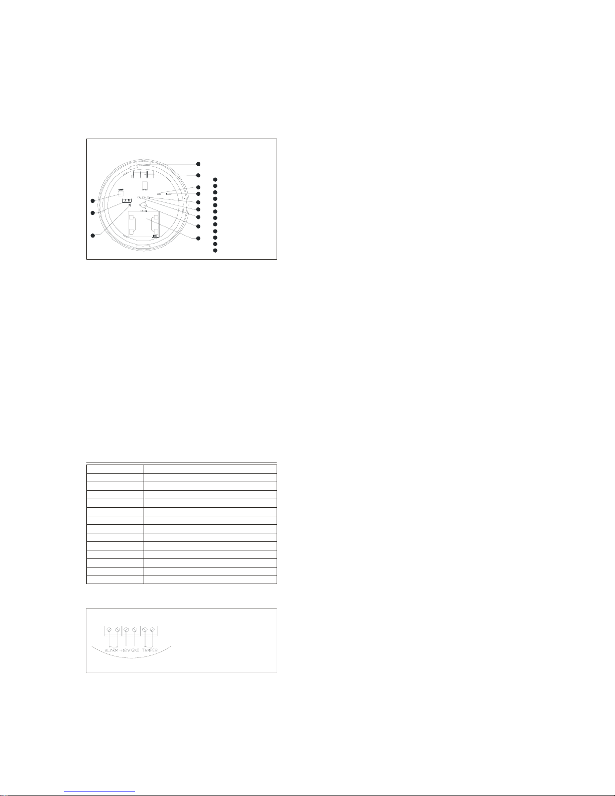
GENERAL VIEW
Wir e e x it
Termin al switch es
LED ju mp e r
RELAY j u mp er
Gr e e n LED
Red LED
Yellow LED
Dual PI R
Microwave module
Micr o wave VR
Anti- tam p er switch
Screw
1
2
3
4
5
6
7
8
9
10
11
12
2
3
4
5
6
7
8
1
9
10
11
12
CHARACTERISTIC
Adopted MCU
Automatic pulse count
Streamline design
Doppler + Power analysis
X-Band plane antenna
Microwave detecting range adjustable
Auto temperature compensation reducing false alarm
Valve adjustable technology with high anti-interference
N.C./N.O. optional for different alarm
Intelligence technology differing intruder from interference signals
SMD technology
TECH. SPECIFICATION
Working voltage
Supply
Detecting range
War m-up time
Detecting mode
Sensor
Microwave antenna
Microwave fr equency
Installation method
Installation height
Working tem per ature
LED indication
Relay outp u t
Anti-tam p e r switch
DC9 16V
18mA ( DC 12V )
diameter:8m (installation height:3.6m)
60s
Dopper+Pow er analysis
dual low noise PIR
plane antenna with high frequency osc illator GaA s :FET
10.525GHz
ceiling mounted
about 2.5-6m
-10 -50
Gr een:infrared Y ellow:microwave Red:alarm
N.C./N.O. optional, 60VDC,100mA
N.C. without voltage output,28VDC,100mA
~
≤
≤
℃℃
TERMINAL BLOCK
+12V:DC ANODE
GND:DC CATHODE
ALARM:RELAY OUTPUT PORT
TAMPER:ANTI-TAMPER SWITCH OUTPUT PORT
Page 2
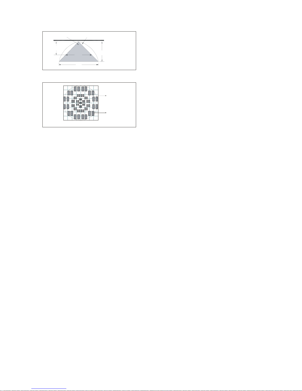
DETECTING RANGE
side view
infrared microwave
8m
5.3m
3.6m
2.4m
top view
0m
2m
4m
2m
4m
0m 2m 4m2m4m
infrared
microwave
INSTALLATION
1. Fix the bracket of detector in the ceiling, after open the front cover and take out the PCB, set the back cover
on bracket by screw.
2. Set the PCB in the back cover after connect the wire according to the TERMINAL BLOCK FIGURE Close
the front cover.
3. The best installation height is 2.5m to 6m.
4. Avoid installing the detector close to the following objects causing temperature changes easily such as
heaters, refrigerators and ovens. Avoid installi ng the detector in the sun directly.
TESTING AND USAGE
1. With 12V power supply, the detector is in self-checking and red LED flashes; The LED is off after 60
seconds and the detector is in operating state.
2. Make walk testing in detecting range, different LED flash: Green LED flashes, infrared is ON; Yellow LED
flashes, microwave is ON; Red LED flashes, infrared & Microwave is ON and the detector is in alarm status.
3. RELAY jumper is used to set alarm output mode. Select different output mode depending on specification of
control: 1&2/N.O. ; 2&3/N.C. ; 2&3 in normal.
4. Microwave VR is used to adjust the detecting range of microwave according to customer's request.
(the largest detection range is set in normal.)
5. LED jumper is used to control LED indication without interference to detector. LED ON jumper can be
interrupted after testing for concealment.
NOTE:
1. Please install and use the Detector following the Directions. Do not touch the sensor surface as this could
result in a detector malfunction. If necessary, clean the sensor surface using a soft cloth with pure alcohol.
2. Avoiding to use the Products in the area with huge change of temperature.
3. For various reasons, including, but not limite d to, changes in environmental conditions, electric or electronic
disruptions and tampering, the Product may not perform as expected. The user is advised to take all necessary
precautions for his/her safety and the protection of his/her property.
4.Changes or modifications not expressly approved by the party responsible for compliance could void the
user's authority to operate the equipment.
 Loading...