

Page 1
P
PRG
DE
EN
FR
ES
RU
Anleitung für Montage und Betrieb
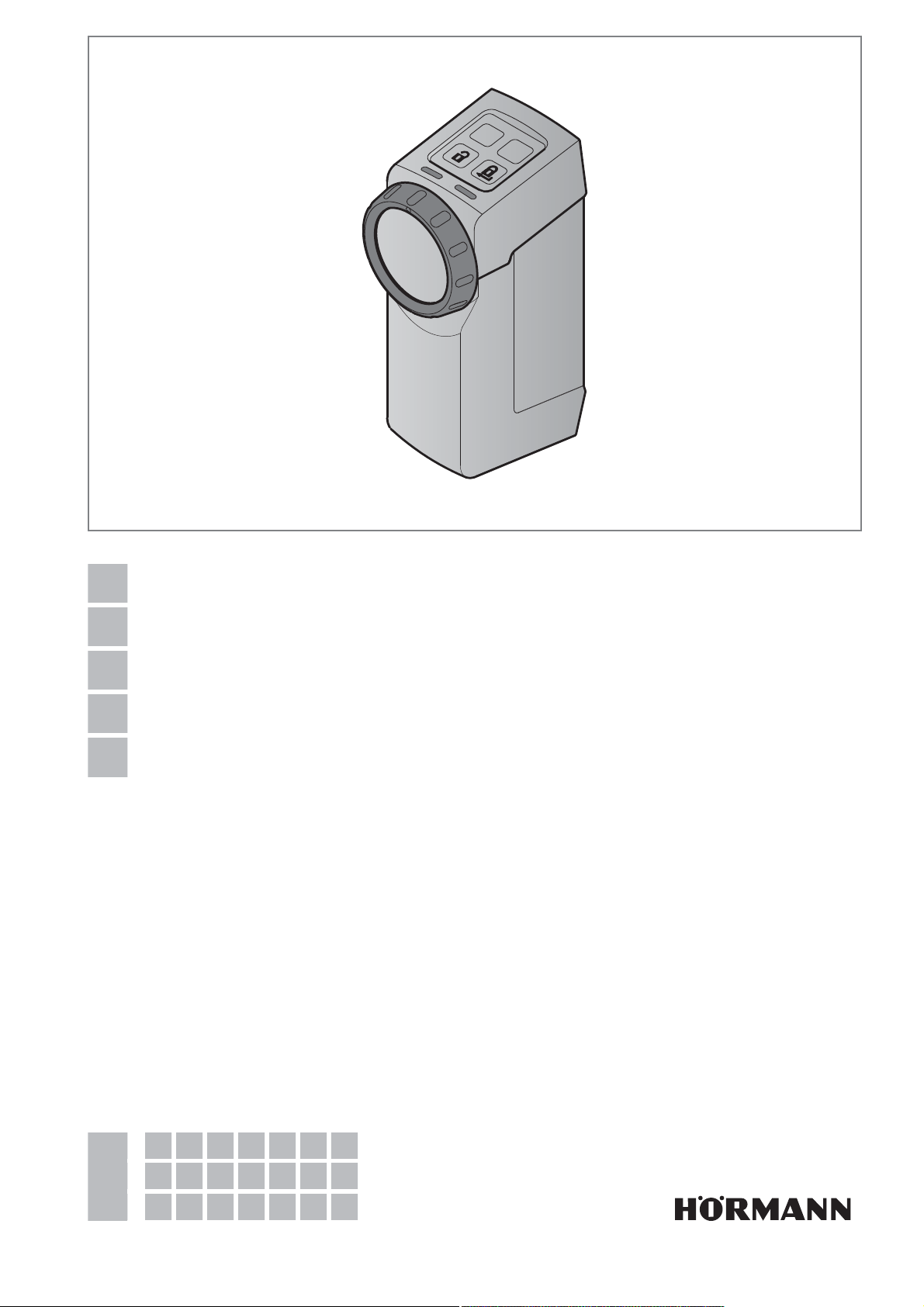
Türschloss-Antrieb SmartKey
Instructions for Fitting and Operating
Door lock operator SmartKey
Instructions de montage et de service
Motorisation de serrure de porte SmartKey
Instrucciones de montaje y funcionamiento
Automatismo de cerradura de puerta SmartKey
Руководство по монтажу и эксплуатации
Привод дверного замка SmartKey
+
4555360 B0 / 42-2023 / DX
NL PL SL FI TR LV EL
IT HU NO DA LT HR RO
PT CS SV SK ET SR BG
Page 2

DEUTSCH ............................ 3
ENGLISH ............................ 23
FRANÇAIS ........................... 43
ESPAÑOL............................ 63
РУССКИЙ ........................... 83
NEDERLANDS....................... 103
ITALIANO........................... 123
PORTUGUÊS........................ 143
POLSKI ............................ 163
MAGYAR ........................... 183
ČESKY ............................. 203
SLOVENSKO ........................ 223
NORSK............................. 243
SVENSKA........................... 263
SUOMI ............................. 283
DANSK............................. 303
SLOVENSKY ........................ 323
TÜRKÇE ........................... 343
LIETUVIŲ KALBA .................... 363
EESTI .............................. 383
LATVIEŠU VALODA................... 403
HRVATSKI .......................... 423
SRPSKI ............................ 443
EΛΛΗΝΙΚΑ.......................... 463
ROMÂNĂ ........................... 483
БЪЛГАРСКИ........................ 503
2 4555360 B0 / 42-2023 / DX
Page 3

Inhaltsverzeichnis
1 Zu dieser Anleitung ...........................................4
1.1 Verwendete Symbole ...........................................4
2 Sicherheitshinweise ..........................................4
2.1 Bestimmungsgemäße Verwendung .....................4
2.2 Nicht bestimmungsgemäße Verwendung............4
2.3 Sicherheitshinweise zum Betrieb ........................4
3 Lieferumfang ......................................................4
4 Produktbeschreibung ........................................5
5 Montage .............................................................6
5.1 Eigenschaften der Tür prüfen ..............................6
5.2 Tür und Profilzylinder prüfen ...............................6
5.3 Schlüsselkopf absägen .......................................6
5.4 Halteblech montieren ..........................................7
6 Inbetriebnahme ..................................................9
6.1 Batterien einlegen ................................................9
6.2 Abschließende Arbeiten.......................................9
6.3 Antrieb einlernen ...............................................10
7 Funktionen .......................................................11
7.1 1.Menüebene / Funktionen ...............................11
7.2 2.Menüebene / Parameter .................................11
8 Funk ..................................................................20
8.1 Integriertes Funkmodul ......................................20
8.2 Handsender .......................................................20
8.3 Lernen der Funkcodes eines Handsenders
HSE4-SK ..........................................................20
8.4 Lernen der Funkcodes eines Sicherungs-
Handsenders HSSE4-SK ..................................20
8.5 Löschen aller Funkcodes...................................20
8.6 Ruhemodus .......................................................21
9 Betrieb ..............................................................21
9.1 Bedienung per Sensorfeld .................................21
9.2 Bedienung per Funk ..........................................21
9.3 Bedienung per Handrad / Schlüssel ..................21
10 Fehlerzustände ................................................21
10.1 Lernfahrten ........................................................21
10.2 Normalbetrieb ....................................................21
11 Reinigung .........................................................22
12 Entsorgung .......................................................22
12.1 Entsorgung von Elektroaltgeräten in
Deutschland ......................................................22
13 Technische Daten ............................................22
14 EU-Konformitätserklärung .............................22
DEUTSCH
Weitergabe sowie Vervielfältigung dieses Dokuments, Verwertung und
Mitteilung seines Inhalts sind verboten, soweit nicht ausdrücklich gestattet.
Zuwiderhandlungen verpflichten zu Schadenersatz. Alle Rechte für den Fall
der Patent-, Gebrauchsmuster- oder Geschmacksmustereintragung
vorbehalten. Änderungen vorbehalten.
4555360 B0 / 42-2023 / DX
3
Page 4
DEUTSCH
1 Zu dieser Anleitung
Die Anleitung enthält wichtige Informationen zum Produkt,
insbesondere Sicherheits- und Warnhinweise.
▶
Lesen Sie die Anleitung sorgfältig durch.
▶
Bewahren Sie diese Anleitung sicher auf.
HINWEIS
Beachten Sie alle am Einsatzort des SmartKey geltenden
Bestimmungen, Normen und Sicherheitsvorschriften.
1.1 Verwendete Symbole
Wichtiger Hinweis
zulässige Anordnung oder Tätigkeit
unzulässige Anordnung oder Tätigkeit
Werkseinstellung
2.2 Nicht bestimmungsgemäße
Verwendung
Der Türschloss-Antrieb darf nicht verwendet werden
– an Brandschutztüren ohne Nachweise
– an Fluchttüren
2.3 Sicherheitshinweise zum Betrieb
WARNUNG
Gefahr im Notfall durch eine abgeschlossene Tür im
Mehrfamilienhaus
In einer Paniksituation kann beim Verlassen eines
Gebäudes eine abgeschlossene Tür ein tödliches
Hindernis sein.
▶
Verwenden Sie den Türschloss-Antrieb nicht an einer
Haupteingangstür eines Mehrfamilienhauses.
ACHTUNG
Beeinträchtigung der Funktion durch Umwelteinflüsse
Bei Nichtbeachtung kann die Funktion beeinträchtigt
werden!
Zulässige Umgebungstemperatur: 0°C bis +40°C.
▶
Führen Sie nach dem Programmieren oder Erweitern
des Funk-Systems eine Funktionsprüfung durch.
▶
Verwenden Sie für die Inbetriebnahme oder die
Erweiterung des Funk-Systems ausschließlich
Originalteile.
• Die örtlichen Gegebenheiten können Einfluss auf die
Reichweite des Funk-Systems haben.
2 Sicherheitshinweise
2.1 Bestimmungsgemäße Verwendung
Der Türschloss-Antrieb ist eine Einheit
– zum motorbetriebenen Verriegeln und Entriegeln,
– für Türen mit maximal 2-tourigen Verriegelungen
(2Schlüsselumdrehungen),
– für trockene Innenräume,
– für Hörmann T30 / EI
Feuerschutztüren mit Rundrosetten-Beschlag der
Baureihen H3OD, STS30 / STU30, D65, STS / STU.
Bei Stahltüren mit Kurzschildbeschlag verwenden Sie eine
Edelstahl-Adapterplatte.
Im Antrieb steckt der Schlüssel in einer Aufnahme, über
den der Profilzylinder verriegelt, entriegelt und geöffnet
werden kann. Der Impuls für den Antrieb erfolgt zum
Beispiel über
– das Sensorfeld mit Tasten,
– einen Handsender,
– einen Funk-Fingerleser,
– die Hörmann Homee App.
Andere Anwendungsarten sind unzulässig. Der Hersteller
haftet nicht für Schäden, die durch bestimmungswidrigen
Gebrauch oder falsche Bedienung verursacht werden.
30 Stahlblech-
2
3 Lieferumfang
• Türschloss-Antrieb SmartKey
• Halteblech
• Handsender HSE4-SK-BS
• 4 × 1,5V Batterie, Typ:AA (LR6), Alkali-Mangan
• Befestigungsmaterial
• Kurzanleitung
4
4555360 B0 / 42-2023 / DX
Page 5
4 Produktbeschreibung
1
DEUTSCH
8
7
6
5
4
P
PRG
3
2
9
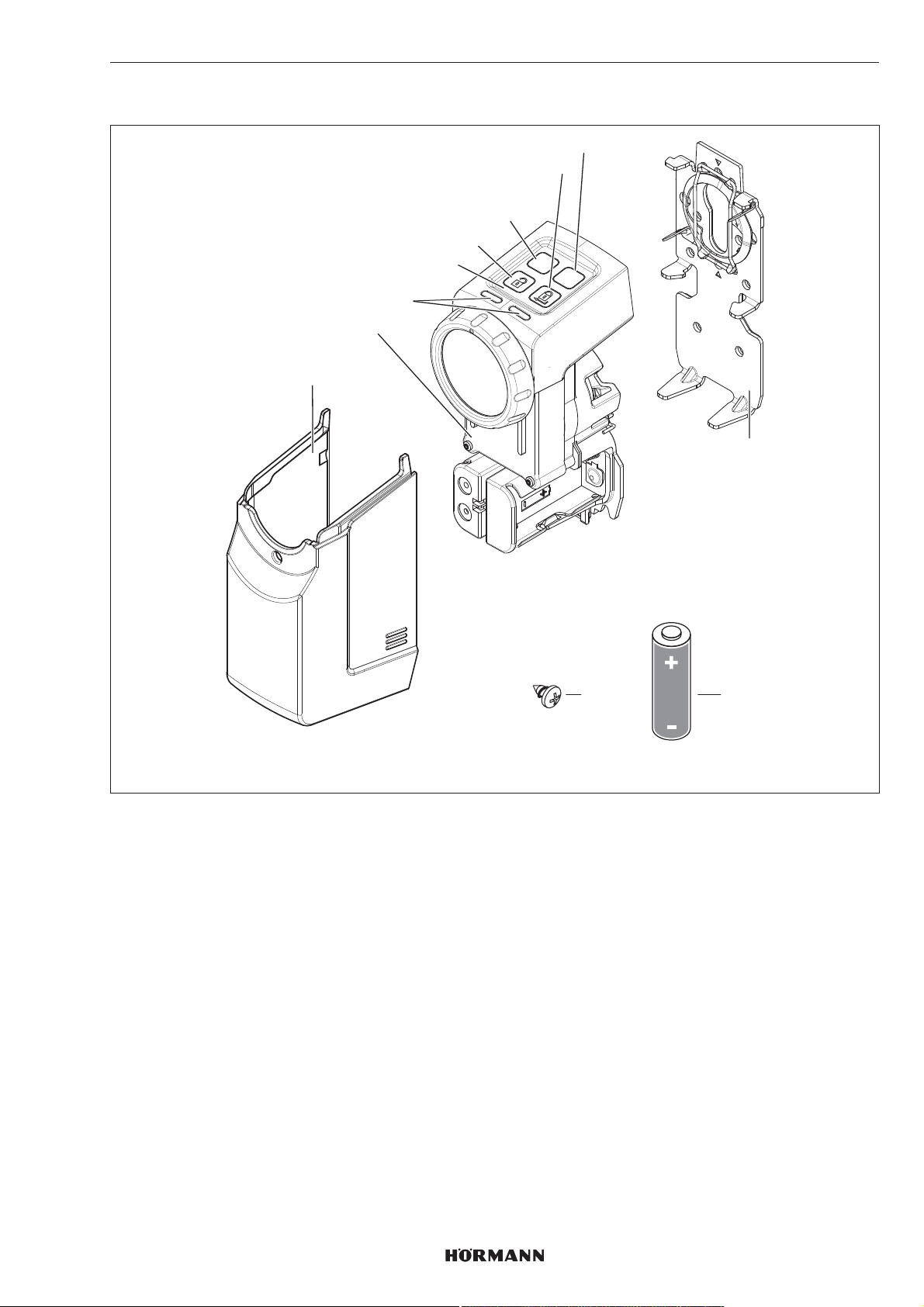
1 Abdeckhaube
2 Antrieb
3 LED (links / rechts), multicolor
4 Sensorfeld mit Tasten
5 Entriegelungs-Taste
6 P-Taste
7 Verriegelungs-Taste
8 PRG-Taste
9 Halteblech
10 1,5V Batterie, Typ AA (LR6), Alkali-Mangan (4 x)
11 Schraube, 4,2 x 9,5mm (4 x)
11
10
AA
4555360 B0 / 42-2023 / DX
5
Page 6
DEUTSCH
5 Montage
Für den Türschloss-Antrieb ist ein im Profilzylinder
dauerhaft eingesteckter Schlüssel erforderlich. Der Zylinder
muss
– ein Euro-Profilzylinder nach DIN18252 und
DIN EN1303 sein.
– die Not- und Gefahrenfunktion besitzen, d.h. wenn
innen ein Schlüssel steckt, dann kann der Zylinder
von außen mit einem anderen Schlüssel geöffnet
werden.
5.1 Eigenschaften der Tür prüfen
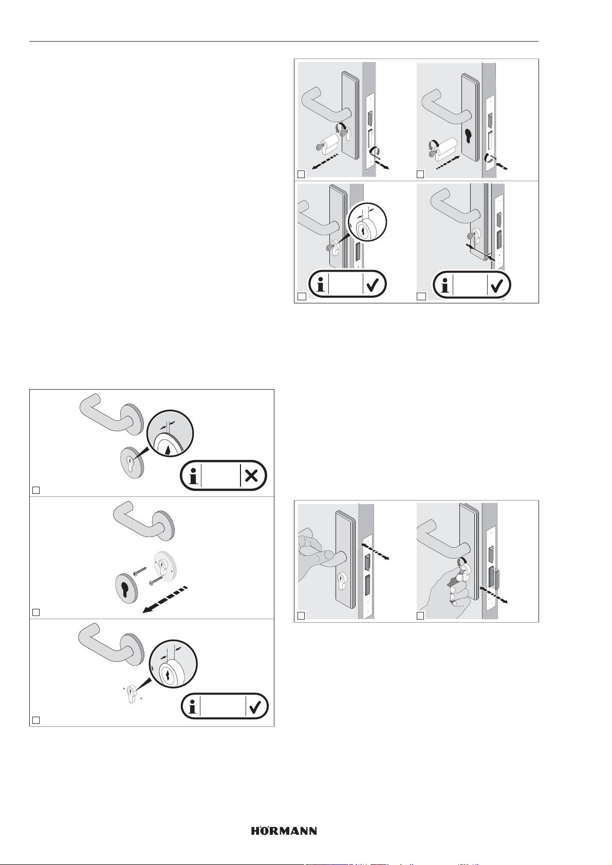
Auf der Innenseite der Tür ist ein Überstand des Zylinders
von 7 – 12mm erforderlich.
▶
Ersetzen Sie den Zylinder, wenn
– der Zylinder keine Not- und Gefahrenfunktion
besitzt
– der Überstand des Zylinders weniger als 7mm
beträgt
TIPP
Wir empfehlen die Montage des Antriebs nach Möglichkeit
direkt auf dem Türblatt.
Das Maß vom Mittelpunkt des Schlüssellochs bis zur
Türaußenkante bzw. Zarge muss mindestens 35 mm sein,
anderenfalls kann die Tür nach der Montage nicht geöffnet
werden.
X
X < 7 mm
1
2.
3.
4
X = 7-12
6
mm
1.
X
1.
2.
5
Y ≥ 35
7
mm
3.
Y
5.2 Tür und Profilzylinder prüfen
Die Tür und der Profilzylinder müssen sich mechanisch in
einem fehlerfreien und leichtgängigen Zustand befinden.
▶
Prüfen Sie vor der Montage des Türschloss-Antriebs
die Einstellung Ihrer Tür und des Zylinders.
▶
Prüfen Sie, ob Ihr Türschloss eine 1-tourige oder
2-tourige Verriegelung hat.
▶
Prüfen Sie, ob bei geöffneter und geschlossener Tür
die gleichen Verriegelungen (1-tourig oder 2-tourig)
möglich sind. Ist bei geschlossener Tür mit einer
2-tourigen Verriegelung nur eine 1-tourige Verriegelung
möglich, dann müssen die Wegfahrten und
Kraftfahrten des Antriebs bei geschlossener Tür
eingelernt werden.
check!
2
X
1
2
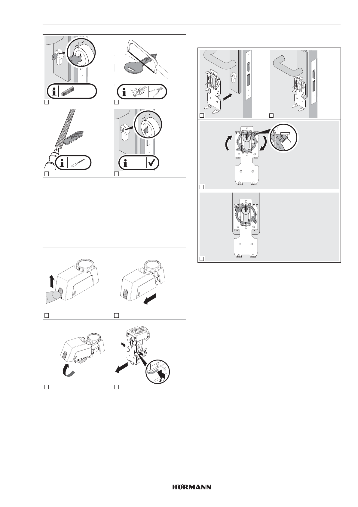
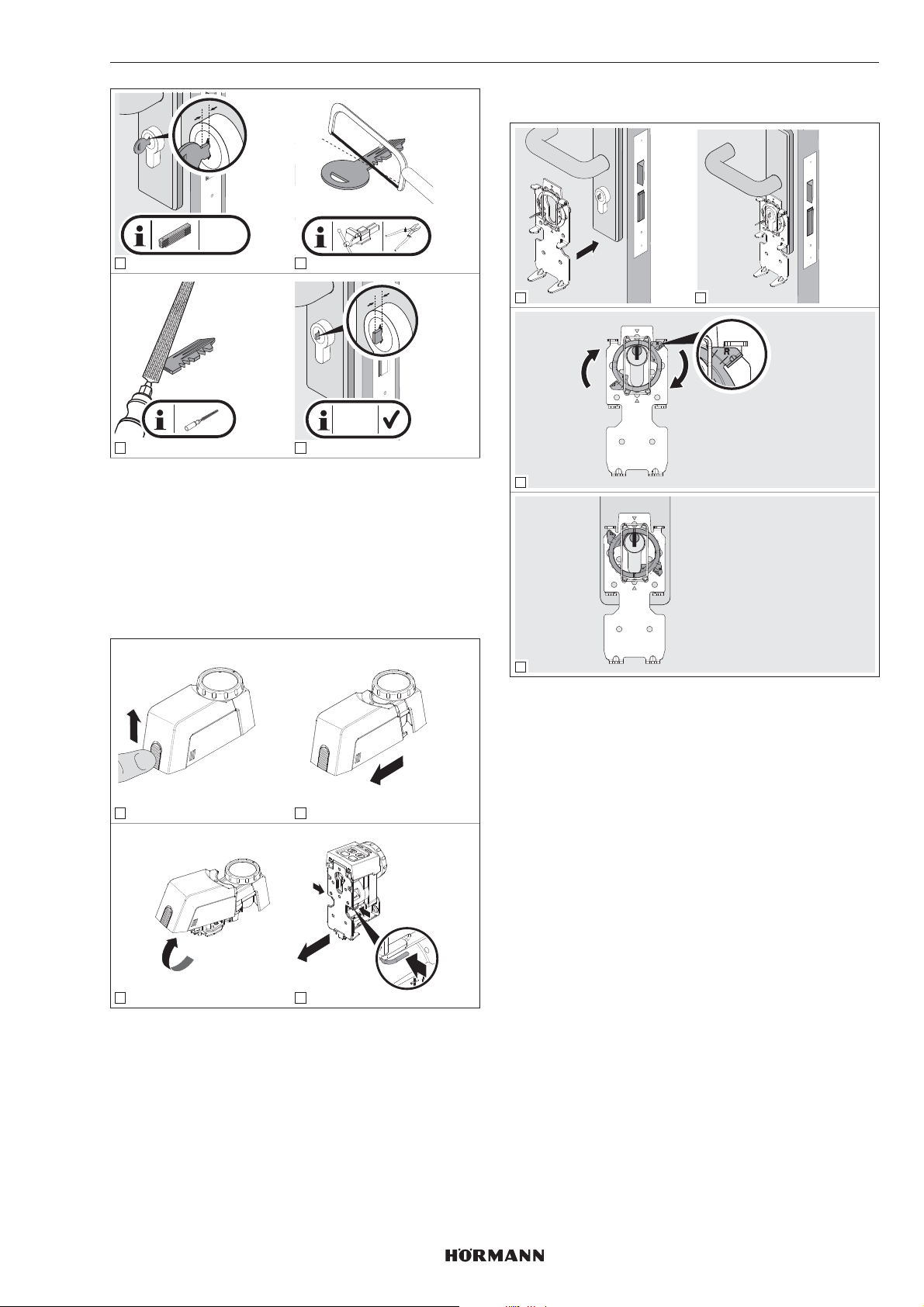
5.3 Schlüsselkopf absägen
check!
1. Entriegeln Sie die Tür.
2. Messen Sie 4 – 7mm zwischen Profilzylinder und
Schlüsselkopf.
X = 7-12 mm
3
6
3. Sägen Sie den Schlüsselkopf ab.
4. Entgraten Sie den Sägeschnitt.
5. Stecken Sie den Schlüssel wieder in den Zylinder.
4555360 B0 / 42-2023/ DX
Page 7
DEUTSCH
y
y = 4-7
mm
1 2
y
y = 4-7
mm
3
4
5.4 Halteblech montieren
1. Entriegeln Sie die Verriegelung und halten Sie sie in
der entriegelten Stellung.
2. Entfernen Sie die Abdeckhaube vom Antrieb.
3. Entriegeln Sie das Halteblech.
4. Ziehen Sie das Halteblech von der Rückseite des
Antriebs ab.
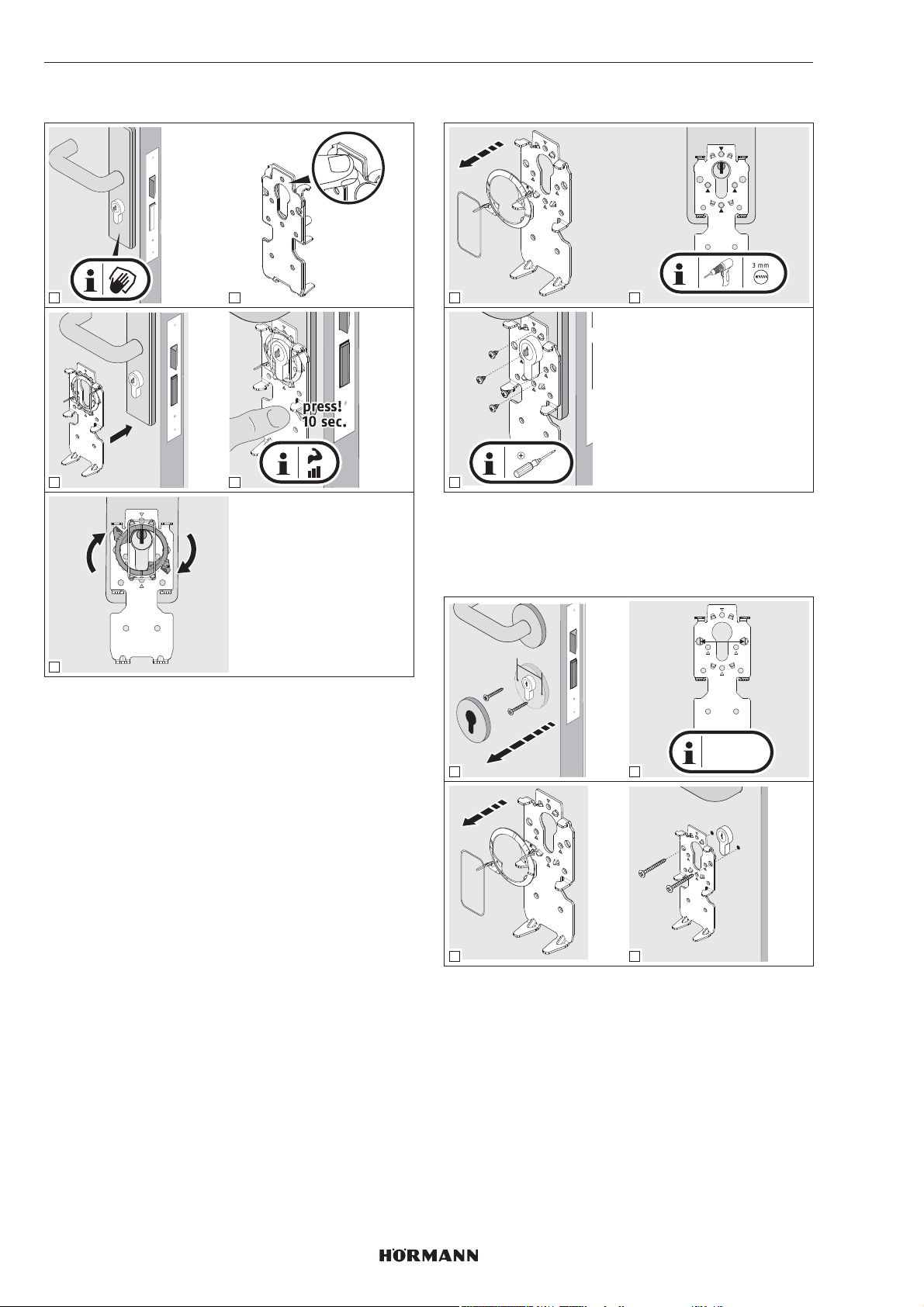
5.4.1 Halteblech festklemmen
1 2
3
1 2
PRG
P
1.
press!
2.
3
4
Für die Montage des Halteblechs gibt es vier
unterschiedliche Möglichkeiten, die kombiniert werden
können:
a. Halteblech festklemmen
▶
siehe Kapitel5.4.1
b. Halteblech ankleben
▶
siehe Kapitel5.4.2
c. Halteblech anschrauben
▶
siehe Kapitel5.4.3
d. Halteblech mit Rosettenverschraubung
▶
siehe Kapitel5.4.4
4
▶
Drehen Sie den Klemmring nach rechts bis zum
Anschlag.
▶
Prüfen Sie anschließend den Profilzylinder. Der
Zylinder muss sich mechanisch in einem fehlerfreien
und leichtgängigen Zustand befinden.
4555360 B0 / 42-2023/ DX
7
Page 8
DEUTSCH
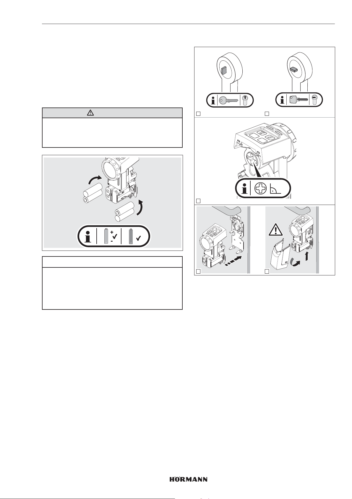
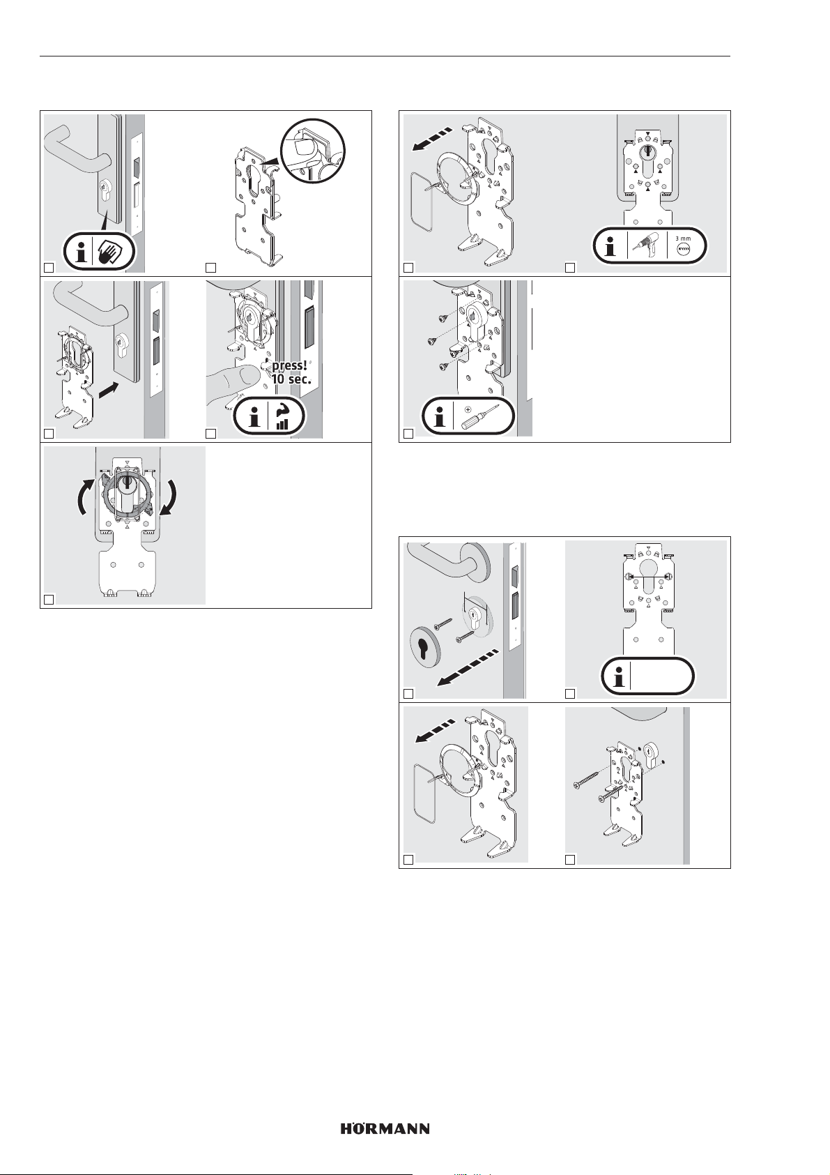
5.4.2 Halteblech ankleben
1 2
3 4
5.4.3 Halteblech anschrauben
1 2
3
▶
Verwenden Sie bei Brandschutztüren kurze
Blechschrauben.
PH2
5
Reinigen der Oberflächen
▶
Verwenden Sie saubere, fusselfreie und parfümfreie
Reinigungstücher.
▶
Verwenden Sie geeignete Reinigungsmittel, keine
rückfettenden Haushaltsreiniger.
▶
Wiederholen Sie die Reinigung, bis die Oberfläche
sauber und fettfrei ist.
HINWEIS
Verwenden Sie stets geeignete Reinigungsmittel und
Pflegemittel. Der Erhalt einer intakten Oberfläche liegt in
Ihrer eigenen Verantwortung.
5.4.4 Halteblech mit Rosettenverschraubung
y
38 mm
y = 38 mm
1
3 4
▶
Achten Sie darauf, dass Sie das Einsteckschloss nicht
anbohren. Kürzen Sie ggf. die Schrauben.
2
8
4555360 B0 / 42-2023/ DX
Page 9
DEUTSCH
6 Inbetriebnahme
Nach dem Einsetzen der Batterien und dem Erlöschen der
blauen LED, ist der Türschloss-Antrieb betriebsbereit.
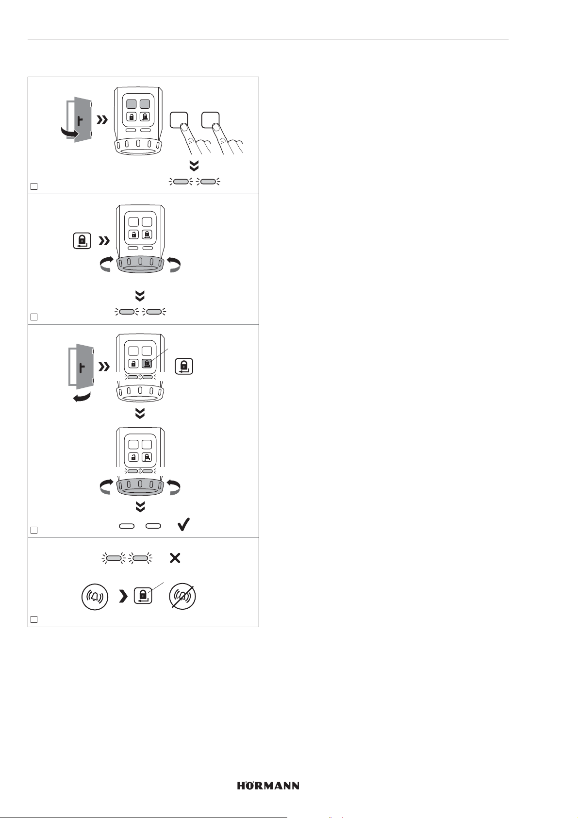
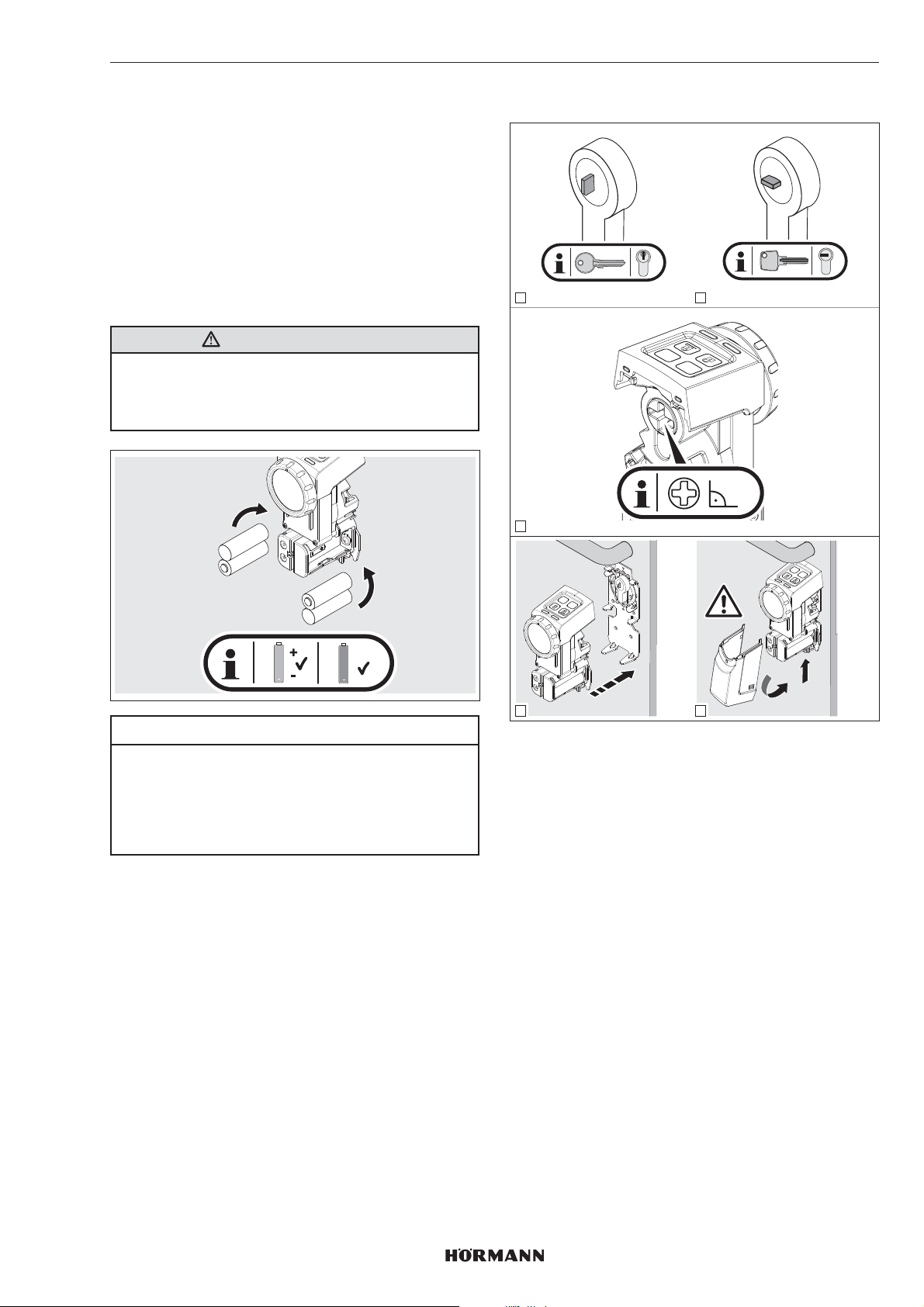
6.1 Batterien einlegen
Verwenden Sie für den Betrieb des Türschloss-Antriebs:
• 4 x 1,5V Batterie, Typ AA (LR6), Alkali-Mangan
oder
• 4 x 1,2V Akku, Typ: AA (HR6), Nickel-Metallhydrid
WARNUNG
Explosionsgefahr durch falschen Batterietyp
Wenn die Batterien durch einen falschen Batterietyp
ersetzt werden, dann besteht die Gefahr einer Explosion.
▶
Verwenden Sie nur den empfohlenen Batterietyp.
6.2 Abschließende Arbeiten
1 2
PRG
P
90°
3
+
AA
+
ACCU
ACCU
ACHTUNG
Zerstörung des Türschloss-Antriebs durch
auslaufende Batterien
Batterien können auslaufen und den Türschloss-Antrieb
zerstören.
▶
Entfernen Sie die Batterien aus dem TürschlossAntrieb, wenn dieser längere Zeit nicht benutzt wird.
P
PRG
P
PRG
2.
click!
4
5
1.
1. Achten Sie auf die entsprechende Stellung für
Zackenschlüssel und Wendeschlüssel.
2. Richten Sie den Kreuzschlitz auf der Rückseite des
Antriebs mit dem Handrad rechtwinklig aus.
3. Stecken Sie den Antrieb auf die Halteplatte.
– Der Antrieb rastet hörbar ein.
4. Verschließen Sie mit der Abdeckhaube den Antrieb.
– Die Abdeckhaube rastet hörbar ein.
4555360 B0 / 42-2023/ DX
9
Page 10
DEUTSCH
6.3 Antrieb einlernen
PRGP
1
ca. 3 sec. - 10 sec.
2
YE YE
press 3 sec.
PRGP
+
YE YE
PRGP
1. Drücken Sie gleichzeitig die P-Taste und die PRG-
Taste und halten Sie die Tasten gedrückt, bis beide
LEDs gelb blinken.
2. Drücken Sie die Verriegelungs-Taste.
Der Antrieb lernt die Wegstrecken von Falle und
Riegel. Nach Erreichen der Endlagen wird der Vorgang
beendet.
3. Schließen Sie die Tür.
4. Drücken Sie die Verriegelungs-Taste.
Der Antrieb lernt die benötigten Kräfte.
5. Der Antrieb ist eingelernt.
Die LEDs erlöschen.
HINWEIS
Wenn die LEDs schnell blinken und ein akustisches Signal
ertönt, muss die Fehlerursache behoben werden.
▶
siehe Kapitel10
6. Prüfen Sie die Funktionen des Antriebs über die Tasten
des Sensorfelds.
Timeout
Wenn innerhalb von 60 Sekunden keine Taste gedrückt
wird, dann wechselt der Türschloss-Antrieb automatisch in
den Betriebsmodus.
Der Antrieb ist ungelernt.
press
PRGP
YE YE
PRGP
YE YE
3
YE YE
press
=
4
Um den Antrieb einzulernen, müssen die folgenden
Voraussetzungen erfüllt sein:
• Der Antrieb ist ungelernt.
• Der Antrieb ist an der Tür montiert.
• Das Schloss muss entriegelt sein, d.h. alle Riegel
müssen komplett eingezogen sein.
• Die Tür ist geöffnet.
10
4555360 B0 / 42-2023 / DX
Page 11
DEUTSCH
7 Funktionen
Die Funktionen des Türschloss-Antriebs lassen sich über
die P-Taste und die PRG-Taste des Sensorfelds einstellen.
Jede Funktion besitzt mehrere Parameter, die weitere
Einstellungen ermöglichen. Vor der ersten Inbetriebnahme
stehen alle Parameter auf Werkseinstellung.
Änderungen der Funktionen sind nur zulässig wenn der
Antrieb ruht.
HINWEIS
Beachten Sie, dass eine Änderung der Werkseinstellung zu
einer geringeren Batterielebensdauer führen kann, zum
Beispiel bei einer Erhöhung des Drehmoments oder der
Geschwindigkeit.
Entsprechend den örtlichen Gegebenheiten und den
individuellen Anpassungen müssen Sie die Funktionen und
die jeweiligen Parameter einstellen.
7.2 2.Menüebene / Parameter
In der 2.Menüebene sind die Parameter der Funktionen
aus der 1.Menüebene hinterlegt. Wenn Sie einen
Parameter einstellen wollen, dann wechseln Sie in die
2.Menüebene.
1. Drücken Sie die P-Taste und halten Sie die Taste für
3Sekunden gedrückt.
Der Türschloss-Antrieb wechselt von der
1.Menüebene in die 2.Menüebene. Je nach
eingestelltem Parameter blinkt die jeweilige LED in der
entsprechenden Farbe.
2. Wählen Sie einen Parameter durch mehrmaliges
kurzes Drücken der PRG-Taste.
Je nach ausgewählter Funktion blinkt die jeweilige LED
in der entsprechenden Farbe.
3. Aktivieren Sie den ausgewählten Parameter, indem Sie
die P-Taste für 3Sekunden drücken.
Wenn der Parameter aktiviert wurde, dann erlöschen
die LEDs kurz und es ertönt ein Signalton.
Anschließend zeigen die LEDs den aktuellen
Parameter an.
4. Drücken Sie die Verriegelungs-Taste kurz
1×Drücken = 1.Menüebene
2×Drücken = Betriebsmodus
Um das Einstellen der Parameter abzubrechen:
▶
Drücken Sie 2× die Verriegelungs-Taste oder warten
Sie auf das Timeout.
7.1 1.Menüebene / Funktionen
In der 1.Menüebene sind die Funktionen des TürschlossAntriebs hinterlegt.
1. Drücken Sie die PRG-Taste und halten Sie die Taste
für 3Sekunden gedrückt.
Der Türschloss-Antrieb wechselt vom Normalbetrieb in
die 1.Menüebene.
2. Wählen Sie eine Funktion durch mehrmaliges kurzes
Drücken der PRG-Taste.
Je nach ausgewählter Funktion leuchtet die jeweilge
LED in der entsprechenden Farbe.
Funktionen LED Kapitel
links rechts
Drehmoment GN 7.2.1
Geschwindigkeit RD 7.2.2
Fallenhaltezeit YE 7.2.3
Signalgeber GN 7.2.4
Sensorfeld mit Tasten RD 7.2.5
Verriegelungsreduzierung YE 7.2.6
Komfortverriegelung GN GN 7.2.7
Geräte-Reset RD RD 7.2.8
GN = Grün, RD = Rot, YE = Gelb
Timeout
Wenn innerhalb von 60 Sekunden keine Taste gedrückt
wird, dann wechselt der Türschloss-Antrieb automatisch in
den Betriebsmodus.
4555360 B0 / 42-2023 / DX
11
Page 12
DEUTSCH
7.2.1 Drehmoment
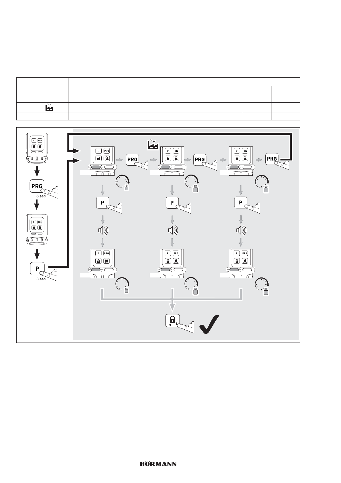
In Abhängigkeit von Türzuständen oder Schließzuständen lässt sich das Drehmoment des Fallenzugs über die Parameter
1-3 einstellen.
HINWEIS
Beachten Sie, dass eine Erhöhung des Drehmoments zu einer höheren Belastung des Schlüssels führt.
Parameter Einstellungen LED
links rechts
1 ca. 1,0Nm 1× GN
2
3 ca. 1,5Nm 3× GN
ca. 1,2Nm 2× GN
GN
1x GN 2x GN 3x GN
ca. 1,0 Nm ca. 1,2 Nm
1x GN 2x GN 3x GN
ca. 1,0 Nm
Nm
3 sec.
Nm
1x
3 sec.
ca. 1,2 Nm
2 x
Nm
Nm
1 x
ca. 1,5 Nm
ca. 1,5 Nm
1 x
Nm
3 sec.
Nm
12
4555360 B0 / 42-2023 / DX
Page 13
DEUTSCH
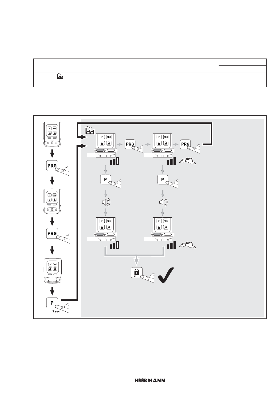
7.2.2 Geschwindigkeit
Die Geschwindigkeit beim Verriegeln, Entriegeln und Öffnen lässt sich über 2Parameter einstellen.
HINWEIS
Beachten Sie, dass eine Erhöhung der Geschwindigkeit zu einer höheren Belastung des Schlüssels führt.
Parameter Einstellungen LED
links rechts
1
2 Maximum 2× RD
TIPP
Wir empfehlen die Automatik-Einstellung beizubehalten, da sich diese automatisch an die unterschiedlichen Gegebenheiten
der Tür anpasst.
Automatik 1× RD
GN
RD
3 sec.
1 x
1x RD 2x RD
3 sec.
1x RD 2x RD
1x
2 x
1 x
3 sec.
4555360 B0 / 42-2023 / DX
13
Page 14
DEUTSCH
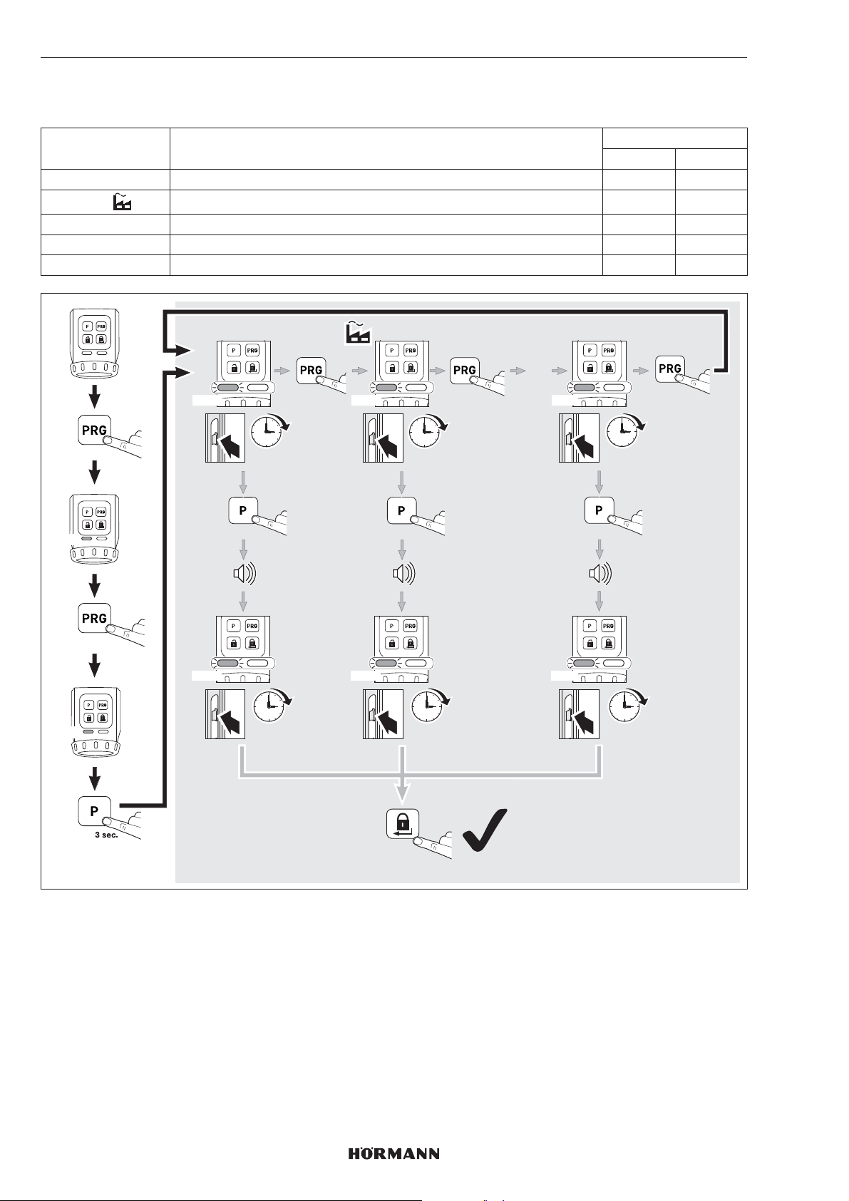
7.2.3 Fallenhaltezeit
Mit der Fallenhaltezeit lässt sich die Zeit einstellen, in der die Falle offen gehalten wird, um die Tür zu öffnen.
Parameter Einstellungen LED
links rechts
1 ca. 1Sekunde 1× YE
2
3 ca. 5Sekunden 3× YE
4 ca. 10Sekunden 4× YE
5 ca. 20Sekunden 5× YE
ca. 3Sekunden 2× YE
GN
YE
3 sec.
2 x
1x YE 2x YE 5x YE
1 sec.
3 sec.
1x YE 2x YE 5x YE
1 sec.
1x
3 sec.
3 sec.
3 sec.
1 x
…
1 x
20 sec.
3 sec.
20 sec.
14
2 x
4555360 B0 / 42-2023 / DX
Page 15
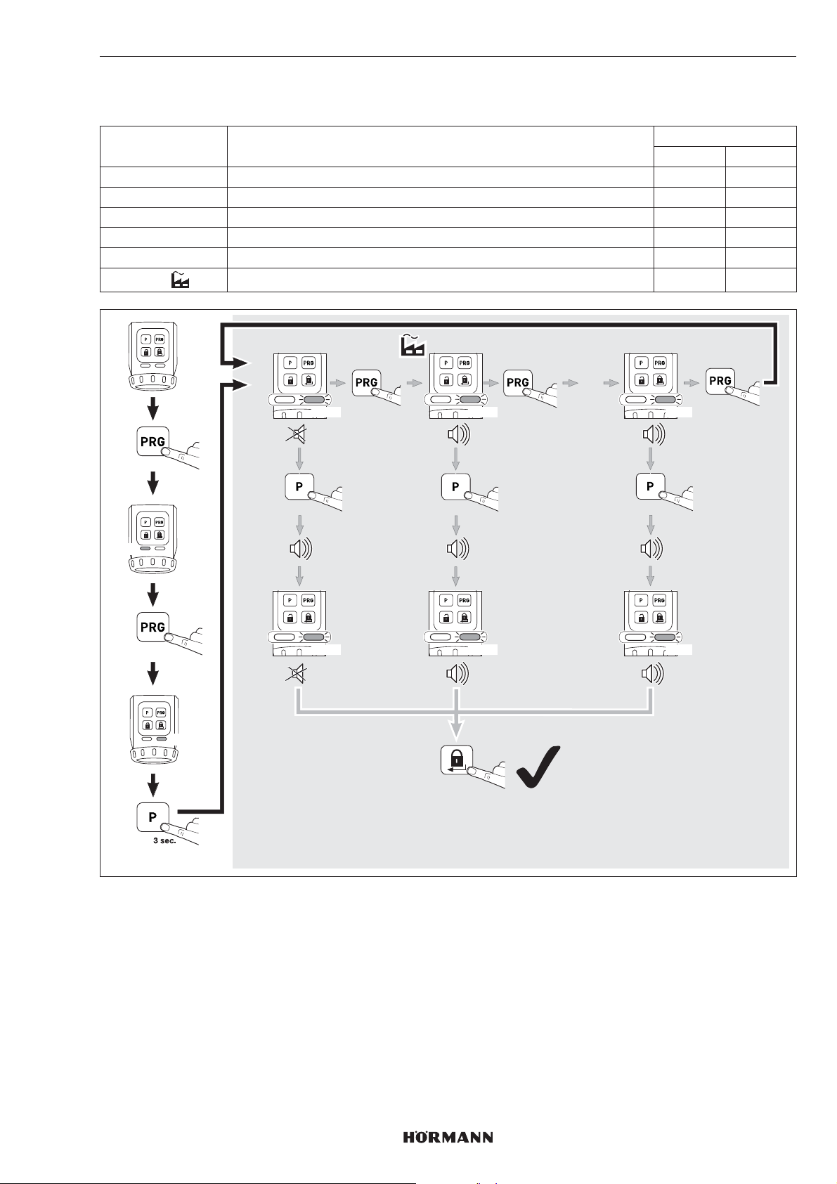
7.2.4 Signalgeber
Mit diesen Parametern lassen sich die Signal-Eigenschaften einstellen.
Parameter Einstellungen LED
1 aus 1× GN
2 nur Tasten 2× GN
3 nur Endlagen 3× GN
4 nur Endlage verriegelt 4× GN
5 Tasten und Endlage verriegelt 5× GN
6
Tasten und Endlagen 6× GN
DEUTSCH
links rechts
GN
3 sec.
3 x
GN
1x GN 2x GN 6x GN
3 sec.
1x GN 2x GN 6x GN
1x
3 sec.
2 x
1 x
…
1 x
3 sec.
4555360 B0 / 42-2023 / DX
15
Page 16
DEUTSCH
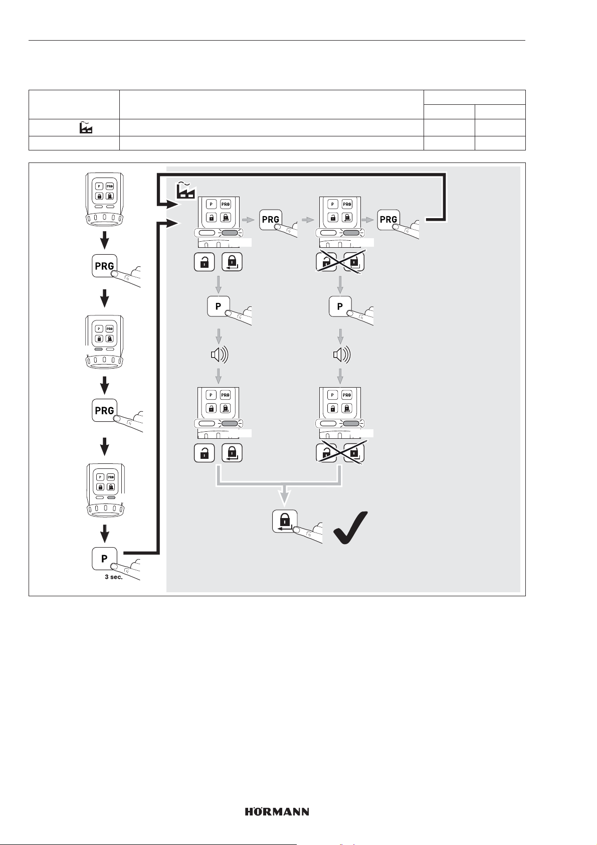
7.2.5 Sensorfeld mit Tasten
Mit diesen Parametern lässt sich die Bedienung der Entriegelungs-Taste und der Verriegelungs-Taste deaktivieren.
Parameter Einstellungen LED
links rechts
1
2 deaktivieren 2× RD
aktivieren 1× RD
GN
3 sec.
4 x
RD
1x RD 2x RD
3 sec.
1x RD 2x RD
1x
1 x
3 sec.
16
2 x
4555360 B0 / 42-2023 / DX
Page 17
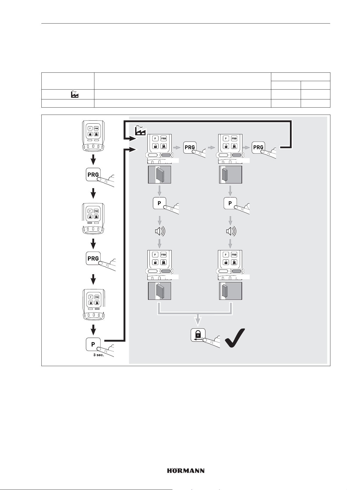
7.2.6 Verriegelungsreduzierung
Mit diesen Parametern lässt sich eine 2-tourige Verriegelung auf eine 1-tourige Verriegelung reduzieren.
HINWEIS
Wir empfehlen, aus Sicherheitsgründen, die Werkseinstellung beizubehalten.
Parameter Einstellungen LED
1
2 nur eine Verriegelung 2× YE
Automatik 1× YE
DEUTSCH
links rechts
GN
3 sec.
5 x
YE
1x YE 2x YE
3 sec.
1x YE 2x YE
1x
1 x
1x
3 sec.
1x
4555360 B0 / 42-2023/ DX
2 x
17
Page 18
DEUTSCH
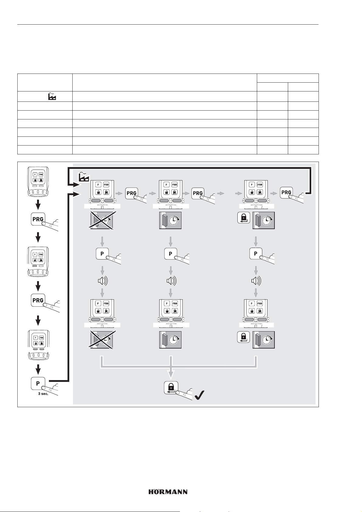
7.2.7 Komfortverriegelung (automatische Verriegelung)
Mit diesen Parametern lässt sich einstellen, ob das Schloss sich nach einer eingestellten Zeit oder nach Tastendruck und
einer eingestellten Zeit automatisch verriegelt.
Achten Sie darauf, dass vor Ablauf der eingestellten Zeit die Tür geschlossen ist, um ein sicheres Verriegeln der Tür zu
gewährleisten.
Parameter Einstellungen LED
links rechts
1
2 ca. 30Sekunden nach dem Erreichen der Endlage Entriegelt 2× GN 2× GN
3 ca. 60Sekunden nach dem Erreichen der Endlage Entriegelt 3× GN 3× GN
4 ca. 120Sekunden nach dem Erreichen der Endlage Entriegelt 4× GN 4× GN
5 ca. 10Sekunden nach dem Drücken der Verriegelungs-Taste 5× GN 5× GN
6 ca. 20Sekunden nach dem Drücken der Verriegelungs-Taste 6× GN 6× GN
7 ca. 30Sekunden nach dem Drücken der Verriegelungs-Taste 7× GN 7× GN
inaktiv 1× GN 1× GN
GN
GN
3 sec.
6 x
GN
1x GN 2x GN 7x GN
1x GN 2x GN 7x GN
1x GN 2x GN 7x GN
3 sec.
1x GN 2x GN 7x GN
1x
ca. 30 sec.
3 sec.
ca. 30 sec.
1 x
…
1 x
ca. 30 sec.
3 sec.
ca. 30 sec.
2 x
Kurzfristiges Deaktivieren der Komfortverriegelung (Parameter 2, 3, und 4)
Sie können die Komfortverriegelung deaktivieren.
▶
Drücken Sie die PRG-Taste.
Die Komfortverriegelung ist deaktiviert.
Mit dem nächsten Verriegeln-Befehl ist die Komfortverriegelung wieder aktiviert.
18
4555360 B0 / 42-2023/ DX
Page 19
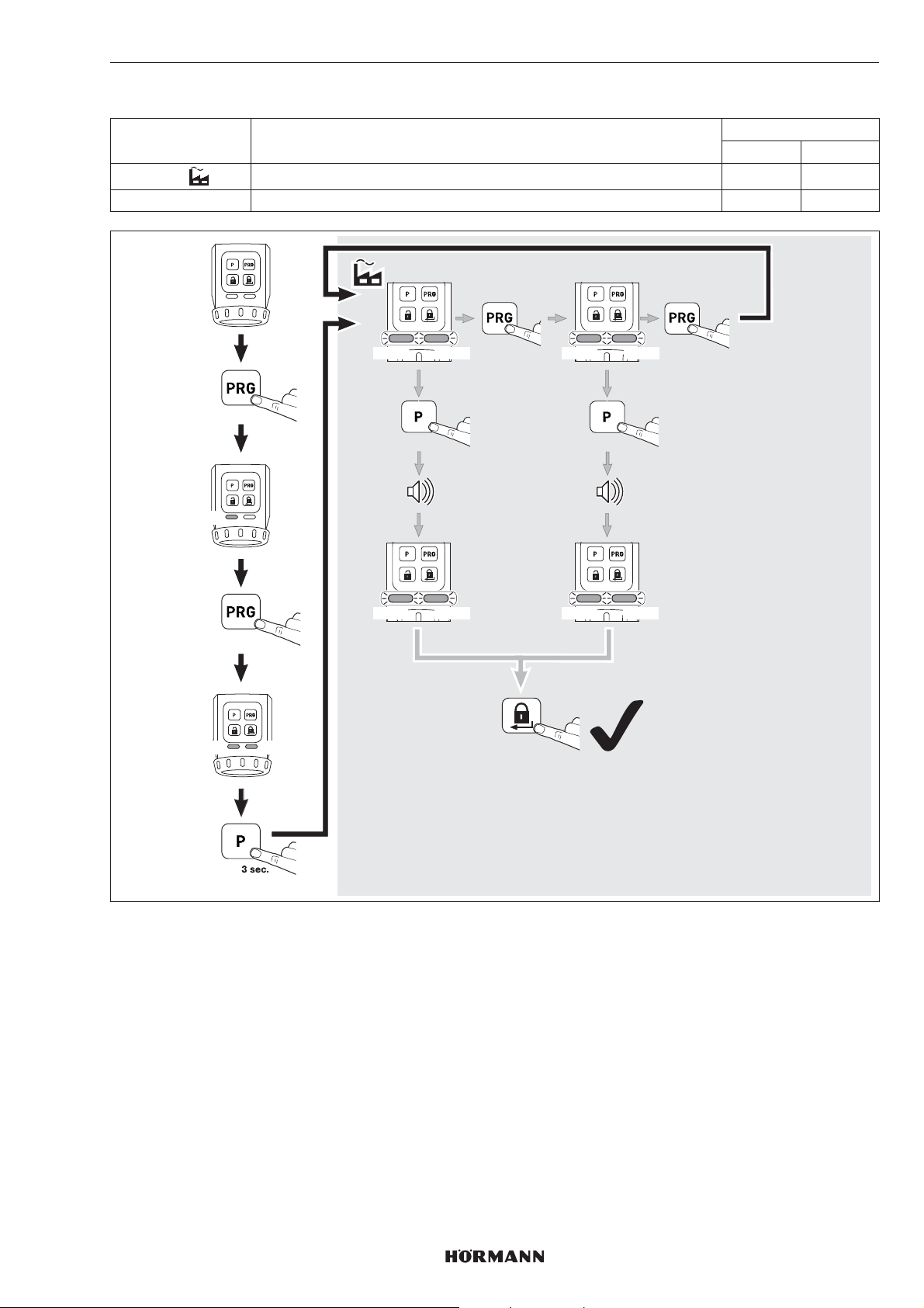
7.2.8 Geräte-Reset
Parameter Einstellungen LED
1
2 Lernfahrten und Funktionen 2× RD 2× RD
nur Lernfahrten 1× RD 1× RD
DEUTSCH
links rechts
GN
RD
3 sec.
7 x
RD
1x RD 2x RD
1x RD 2x RD
1x RD 2x RD
3 sec.
1x RD 2x RD
1x
2 x
1 x
3 sec.
4555360 B0 / 42-2023/ DX
19
Page 20
DEUTSCH
8 Funk
8.1 Integriertes Funkmodul
Es können max. 100Funkcodes von 4-Tasten-Handsender
HSE 4-SK-BS oder von Sicherungs-Handsender
HSSE4-SK übertragen und auf die vorhandenen Kanäle
aufgeteilt werden. Wenn mehr als 100Funkcodes
übertragen werden, dann werden die zuerst eingelernten
Funkcodes gelöscht.
Die Funkcodes anderer Sender* können am TürschlossAntrieb nicht eingelernt werden. Dafür können der
4-Tasten-Handsender HSE 4-SK-BS und der SicherungsHandsender HSSE 4-SK ihre Funkcodes auf andere
BiSecur-Sender* vererben.
8.2 Handsender
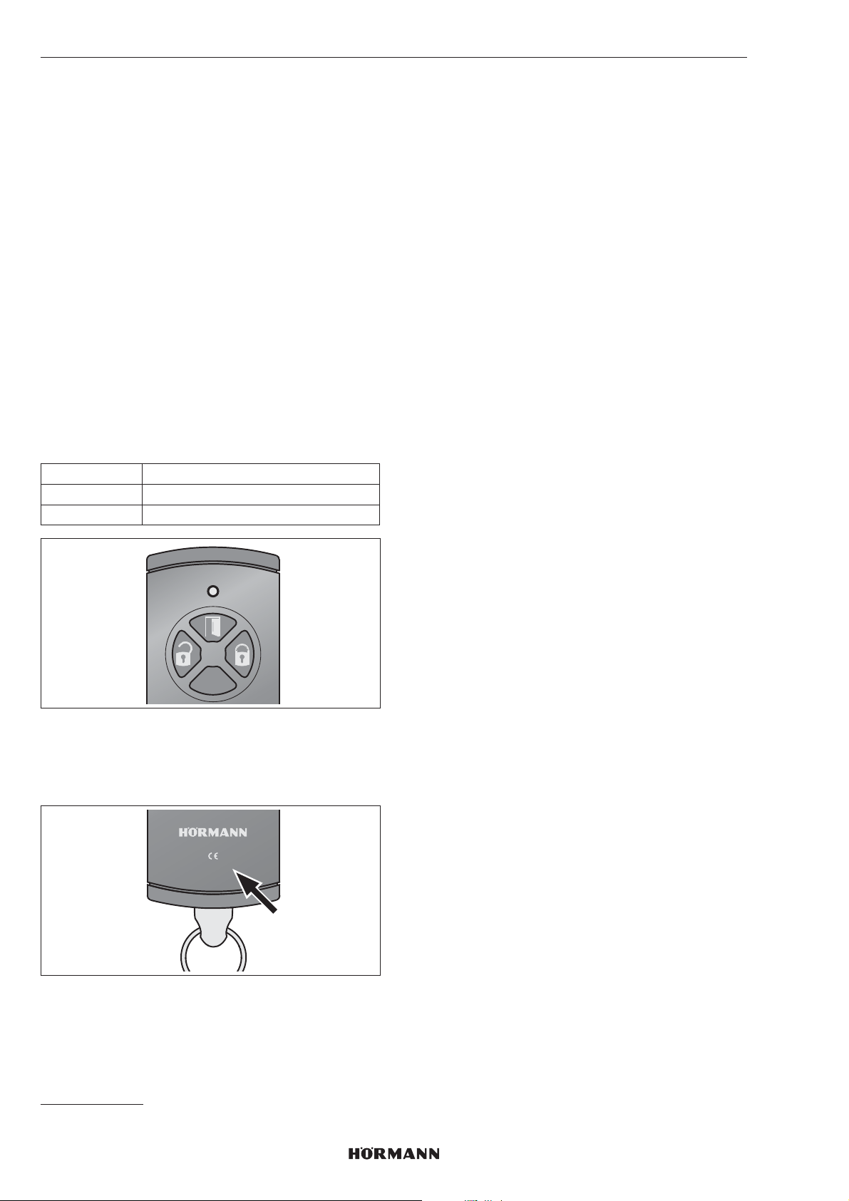
Dem Türschloss-Antrieb liegt ein 4-Tasten-Handsender
HSE4-SK bei, dessen Funkcodes am Türschloss-Antrieb
eingelernt werden müssen.
▶
siehe Kapitel8.3
Tastenbelegung
links entriegeln
oben öffnen
rechts verriegeln
8.3 Lernen der Funkcodes eines
Handsenders HSE4-SK
Beim Lernen der Funkcodes eines Handsenders HSE4SK
werden alle 3Kanäle gleichzeitig eingelernt.
1. Drücken Sie die P-Taste vom Türschloss-Antrieb 1×
kurz.
– Die rechte LED blinkt langsam blau.
2. Halten Sie den Handsender vor den Türschloss-
Antrieb.
3. Drücken Sie am Handsender die Öffnen-Taste und
halten Sie diese gedrückt.
– Die LED leuchtet 2 Sekunden blau und erlischt.
– Nach 5 Sekunden blinkt die LED abwechselnd rot
und blau.
– Der Handsender sendet die Funkcodes.
4. Wenn die Funkcodes erkannt sind, blinkt die LED vom
Antrieb schnell blau.
– Nach 2 Sekunden erlischt die LED.
5. Lassen Sie die Handsendertaste los.
6. Drücken Sie die P-Taste, um den Lernvorgang
abzuschließen.
Die Funkcodes des Handsenders sind gelernt.
8.4 Lernen der Funkcodes eines
Sicherungs-Handsenders HSSE4-SK
Beim Lernen der Funkcodes eines SicherungsHandsenders HSSE 4-SK werden alle 3 Kanäle gleichzeitig
eingelernt.
Anschließend können keine weiteren Handsender
HSE4-SK oder HSSE4-SK mit der Index-Angabe -3 am
Antrieb eingelernt werden. Ein Weitervererben auf andere
Sender* kann nur über einen Kopiervorgang vom
Sicherungs-Handsender erfolgen.
HINWEIS
Zu Ihrer eigenen Sicherheit empfehlen wir die am
Türschloss-Antrieb zuvor gelernten Funkcodes zu löschen,
wenn Sie
HINWEIS
Das Vererben der Funkcodes vom Handsender HSE4SK
auf andere Sender* ist nicht möglich, wenn kein Index
vorhanden ist oder die Index-Angabe -1 bzw. -2 ist.
HSE4-868-BS
0498-2
* z.B. Handsender, Gateway
– einen Sicherungs-Handsender einlernen.
– am Sicherungs-Handsender einen Geräte-Reset
durchgeführt haben.
▶
siehe Kapitel8.3
Die Funkcodes des Sicherungs-Handsenders sind
gelernt.
HINWEIS
Zum Vererben / Senden des Funkcodes haben Sie
25Sekunden Zeit. Wenn innerhalb dieser Zeit das
Vererben / Senden nicht erfolgreich ist, wiederholen Sie den
Vorgang.
8.5 Löschen aller Funkcodes
Die Funkcodes einzelner Sendetasten oder einzelne
Funktionen können Sie nicht löschen.
▶
Drücken Sie die P-Taste und halten Sie diese Taste
gedrückt.
– Die LED blinkt 5 Sekunden langsam blau.
– Die LED blinkt 2 Sekunden schnell blau.
– Die LED erlischt.
Alle Funkcodes sind gelöscht.
20
4555360 B0 / 42-2023 / DX
Page 21

DEUTSCH
8.6 Ruhemodus
Wenn der Ruhemodus aktiviert ist
– kann der Antrieb nicht per Funk bedient werden,
– wird die Batterie-Lebensdauer erhöht.
8.6.1 Aktivieren des Ruhemodus
▶
Drücken Sie die Verriegelungs-Taste auf dem
Sensorfeld für 5Sekunden.
Der Antrieb fährt in die Endlage Schloss-Verriegelt, der
Ruhemodus ist aktiviert und die rechte LED blinkt 5×
blau.
HINWEIS
Befindet sich der Antrieb bereits in der Endlage Verriegelt,
dann wird der Ruhemodus sofort aktiviert.
8.6.2 Deaktivieren des Ruhemodus
▶
Drücken Sie die Entriegelungs-Taste oder die
Verriegelungs-Taste auf dem Sensorfeld.
Der Ruhemodus ist deaktiviert und die rechte LED
leuchtet 2Sekunden blau.
HINWEIS
Durch Bedienung des Handrads oder des Schlüssels wird
der Ruhemodus ebenfalls deaktiviert.
9 Betrieb
9.1 Bedienung per Sensorfeld
Für die Bedienung über das Sensorfeld sind die Tasten
Entriegeln/Öffnen und Verriegeln zu verwenden.
9.2 Bedienung per Funk
HINWEIS
Wenn der Funkcode der Handsendertaste von einem
anderen Handsender vererbt ist, dann drücken Sie die
Handsendertaste zum ersten Betrieb 2×.
9.3 Bedienung per Handrad / Schlüssel
Die Bedienung per Handrad / Schlüssel ist nur für den
Notfall vorgesehen.
HINWEIS
Nach der Entriegelung über das Handrad oder mit einem
Schlüssel erfolgt bei der nächsten Bedienung automatisch
eine Referenzfahrt des Antriebs. Dabei blinkt die linke LED
rot.
10 Fehlerzustände
10.1 Lernfahrten
Meldung Ursache Abhilfe
akustisches Signal
(60 Sek.) und
beide LEDs
blinken gelb
Fehler während
der Lernfahrt
Drücken einer
Taste auf dem
Sensorfeld
10.2 Normalbetrieb
Meldung Ursache Abhilfe
akustisches Signal
für 3Sek.,
anschließend
blinkt die linke LED
3Sek. gelb
akustisches Signal
(60Sek.) und die
linke LED blinkt
gelb
akustisches Signal
(60Sek.) und die
linke LED blinkt rot
niedriger
Batteriestand
Fehler während
einer Fahrt /
Referenzfahrt
Fehler während
einer
Referenzfahrt
Alle Batterien
gleichzeitig
wechseln
Drücken einer
Taste auf dem
Sensorfeld
erneuter
Fahrbefehl per
Funk (nur Öffnen
oder Entriegeln)
Drücken einer
Taste auf dem
Sensorfeld
erneuter
Fahrbefehl per
Funk (nur Öffnen
oder Entriegeln)
4555360 B0 / 42-2023 / DX
21
Page 22
DEUTSCH
11 Reinigung
ACHTUNG
Beschädigung des Türschloss-Antriebs durch falsche
Reinigung
Das Reinigen des Türschloss-Antriebs mit ungeeigneten
Reinigungsmitteln kann das Gehäuse sowie die Tasten
angreifen.
▶
Reinigen Sie den Türschloss-Antrieb nur mit einem
sauberen und feuchten Tuch.
12 Entsorgung
Verpackung sortenrein entsorgen.
Elektro- und Elektronik-Geräte müssen in den dafür
eingerichteten Annahme- und Sammelstellen
abgegeben werden.
Batterien getrennt entsorgen. Jeder Verbraucher ist
gesetzlich verpflichtet, Batterien bei einer
Sammelstelle seiner Gemeinde, seines Stadtteils
oder im Handel abzugeben.
12.1 Entsorgung von Elektroaltgeräten in
Deutschland
Wichtige Informationen nach dem Elektro- und
Elektronikgerätegesetz (ElektroG)
Wir weisen Besitzer von Elektro- und Elektronikaltgeräten
darauf hin, dass Elektroaltgeräte gemäß den geltenden
gesetzlichen Vorschriften einer vom Siedlungsabfall
getrennten Entsorgung zuzuführen sind.
zurücknehmen, ohne dass dies an einen Neukauf geknüpft
werden darf (0:1-Rücknahme).
Daneben ist die Rückgabe von Elektroaltgeräten auch bei
einer offiziellen Abgabestelle der öffentlich-rechtlichen
Entsorgungsträger möglich.
Löschung personenbezogener Daten
Für die Löschung personenbezogener Daten auf den zu
entsorgenden Elektroaltgeräten sind Sie als Endnutzer vor
der Abgabe selbst verantwortlich.
13 Technische Daten
Türschloss-Antrieb
Modell SmartKey
Frequenz 868MHz
Sendeleistung max. 10mW (EIRP)
Spannungsversorgung • 4 x 1,5V Batterie, Typ AA
(LR6), Alkali-Mangan
oder
• 4 x 1,2V Akku, Typ: AA
(HR6), Nickel-Metallhydrid
zul.
Umgebungstemperatur
Schutzart IP20
0°C bis +40°C
14 EU-Konformitätserklärung
Hiermit erklärt die Hörmann KG Verkaufsgesellschaft, dass
der Funkanlagentyp SmartKey-868-BS der
Richtlinie 2014/53/EU entspricht.
Der vollständige Text der EU-Konformitätserklärung kann
der folgenden Internet adresse entnommen werden:
Entsorgung
In den Elektroaltgeräten enthaltene Batterien und
Akkumulatoren, die nicht fest vom Elektroaltgerät
umschlossen sind, sowie Lampen, die zerstörungsfrei aus
dem Elektroaltgerät entnommen werden können, sind vor
deren Abgabe an einer Entsorgungsstelle zerstörungsfrei
von diesem zu trennen und einer vorgesehenen Entsorgung
zuzuführen. Soweit unsere Geräte Batterien oder
Akkumulatoren enthalten, entnehmen Sie weitere
Informationen zum Typ und chemischen System der
Batterie sowie zu deren Entnahme, der
Bedienungsanleitung des jeweiligen Geräts.
Das folgend dargestellte und auf Elektro- und
Elektronikalt geräten aufgebrachte Symbol einer
durchgestrichenen Abfalltonne weist zusätzlich
auf die Pflicht zur getrennten Entsorgung hin.
Rückgabe im Einzelhandel oder beim
Entsorgungsträger
Elektrofachmärkte und Lebensmittelläden sind nach §17
ElektroG unter bestimmten Voraussetzungen zur
Rücknahme von Elektro- und Elektronikaltgeräten
verpflichtet. Stationäre Vertreiber müssen bei Verkauf eines
neuen Elektro- und Elektronikgeräts ein Elektroaltgerät der
gleichen Art kostenfrei zurücknehmen (1:1-Rücknahme).
Dies gilt auch bei Lieferungen nach Hause. Diese Vertreiber
müssen außerdem bis zu 3 kleine Elektroaltgeräte (≤ 25cm)
www.hoermann-docs.com/277127
22
4555360 B0 / 42-2023 / DX
Page 23

Table of contents
1 About these instructions .................................24
1.1 Symbols used ....................................................24
2 Safety instructions ...........................................24
2.1 Intended use ......................................................24
2.2 Non-intended use ..............................................24
2.3 Safety instructions for operation .......................24
3 Scope of delivery .............................................24
4 Product description .........................................25
5 Fitting ................................................................26
5.1 Checking the door features ...............................26
5.2 Check door and profile cylinder ........................26
5.3 Saw off key head ...............................................26
5.4 Fit retaining plate ...............................................27
6 Initial start-up ...................................................29
6.1 Inserting the batteries ........................................29
6.2 Final work ..........................................................29
6.3 Teaching in the operator ....................................30
7 Functions ..........................................................31
7.1 1st menu level / functions ..................................31
7.2 2nd menu level / parameters ..............................31
8 Radio .................................................................40
8.1 Integrated radio module ....................................40
8.2 Hand transmitters ..............................................40
8.3 Teaching in the radio codes of hand transmitter
HSE 4-SK ..........................................................40
8.4 Teaching in the radio codes of security hand
transmitter HSSE 4-SK ......................................40
8.5 Deleting all radio codes .....................................41
8.6 Sleep mode .......................................................41
9 Operation ..........................................................41
9.1 Operation via sensor field ..................................41
9.2 Operation via radio ............................................41
9.3 Operation via hand wheel / key ..........................41
10 Error states ......................................................41
10.1 Learning runs .....................................................41
10.2 Normal operation ...............................................41
11 Cleaning ............................................................42
12 Disposal ............................................................42
13 Technical data ..................................................42
14 EU and UK Declaration of Conformity ...........42
ENGLISH
Dissemination as well as duplication ofthis document and the use and
communication of its content are prohibited unless explicitly permitted.
Noncompliance will result in damage compensation obligations. All rights
reserved in the event of patent, utility model or design model registration.
Subject to changes.
4555360 B0 / 42-2023 / DX
23
Page 24
ENGLISH
1 About these instructions
These instruction contains important information on the
product, and especially safety instructions and warnings.
▶
Read through the instructions carefully.
▶
Keep these instructions in a safe place.
NOTICE
Observe all specifications, standards and safety
regulations applicable at the location where the SmartKey
is installed.
1.1 Symbols used
Important note
Permissible arrangement oractivity
Non-permissible arrangement or activity
2.3 Safety instructions for operation
WARNING
Danger in an emergency due to a locked door ina
multi-family home
In a panic situation, a locked door may be fatal
ifattempting to leave the building.
▶
Do not use the door lock operator at the main
entrance of a multi-family home.
ATTENTION
Functional impairment caused by environmental
conditions
Non-compliance with these instructions can impair
function!
Permissible ambient temperature: 0°C to +40°C.
▶
After programming or extending the radio system,
check the functions.
▶
Only use original components when putting the radio
system into service or extending it.
• Local conditions may affect the range of the radio
system.
Factory setting
2 Safety instructions
2.1 Intended use
The door lock operator is a unit
– for motor-operated locking and unlocking,
– for doors with maximum 2-turn locking (2turnsof
the key),
– for dry interiors,
– for Hörmann T30 / EI
with round rose escutcheon fitting from series
H3OD, STS30 / STU30, D65, STS / STU.
Use a stainless steel adapter plate for steel doors with
short escutcheon fitting.
The key is located in a holder in the operator, via which the
profile cylinder can be locked, unlocked, and opened.
The impulse for the operator may, forexample, come from
– the sensor field with buttons,
– a hand transmitter,
– a radio finger-scan,
– the Hörmann Homee App.
Other applications are not permitted. The manufacturer is
not liable for damages caused byimproper use or incorrect
operation.
30 sheet steel fire-rated doors
2
3 Scope of delivery
• Door lock operator SmartKey
• Retaining plate
• Hand transmitter HSE4-SK-BS
• 4 × 1.5V battery, type:AA (LR6), alkali-manganese
• Fixing material
• Brief instructions
2.2 Non-intended use
The door lock operator may not be used
– on fire-rated doors without verifications
– on escape doors
24
4555360 B0 / 42-2023 / DX
Page 25
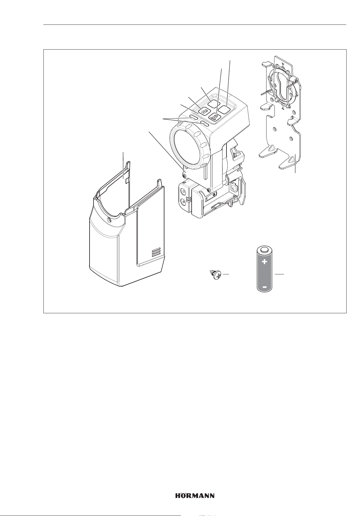
4 Product description
1
ENGLISH
8
7
6
5
4
P
PRG
3
2
9
1 Cover
2 Operator
3 LED (left/right), multicolour
4 Sensor field with buttons
5 Release button
6 P button
7 Locking button
8 PRG button
9 Retaining plate
10 1.5V battery, type:AA (LR6), alkali-manganese (4 x)
11 Screw, 4.2 × 9.5mm (4 x)
11
10
AA
4555360 B0 / 42-2023 / DX
25
Page 26
ENGLISH
5 Fitting
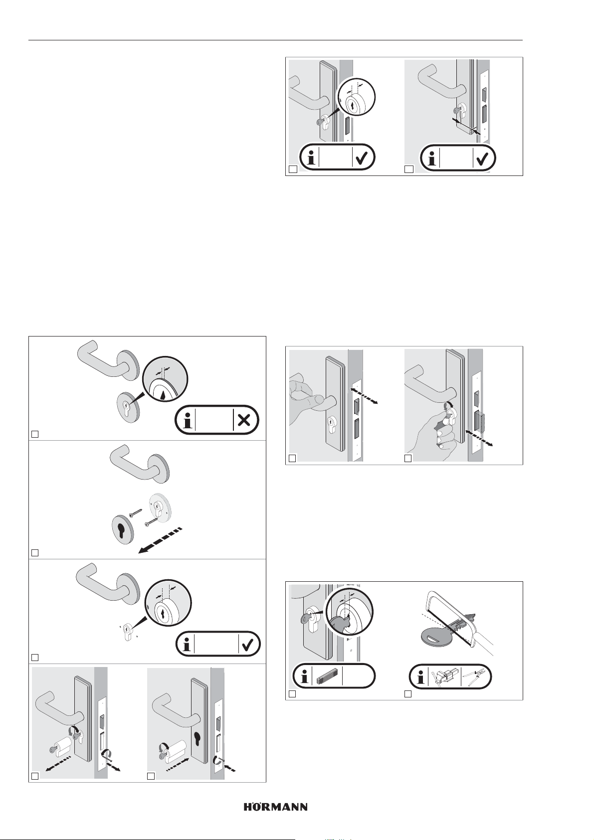
A key that is permanently inserted in the profile cylinder is
required for the door lock operator. Thecylinder must
– be a Euro profile cylinder in accordance with
DIN18252 and DINEN1303.
– have an emergency and hazard function, i.e.ifa key
is inserted on the inside, thecylinder can be opened
from the outside using another key.
5.1 Checking the door features
The cylinder must protrude 7 – 12mm on the inside ofthe
door.
▶
Replace the cylinder if
– the cylinder does not have an emergency and
hazard function
– the cylinder protrudes less than 7mm
TIP
If possible, we recommend directly fitting the operator on
the door leaf.
The dimension from the centre of the keyhole to the outer
edge of the door or the frame must be at least 35mm,
otherwise the door cannot be opened after fitting.
X
Y
X = 7-12
6
mm
7
Y ≥ 35
mm
5.2 Check door and profile cylinder
The door and profile cylinder must be in a flawless
mechanical condition and easy to move.
▶
Check the adjustment of your door and cylinder before
fitting the door lock operator.
▶
Check whether your door lock is equipped with 1-turn
or 2-turn locking.
▶
Check whether the same locking (1-turn or 2-turn) is
possible when the door is open and closed. Ifonly
1-turn locking is possible in a door with 2-turn locking
when it is closed, the travel and power runs must be
taught in when the door isclosed.
X
X < 7 mm
1
1
check!
2
check!
5.3 Saw off key head
1. Unlock the door.
2. Measure 4 – 7mm between the profile cylinder and key
head.
3. Saw off the key head.
2
X
X = 7-12 mm
3
4. Deburr the sawed edge.
5. Reinsert the key in the cylinder.
y
y = 4-7
mm
1 2
26
2.
3.
4
1.
1.
2.
5
3.
4555360 B0 / 42-2023/ DX
Page 27
y
y = 4-7
mm
3
4
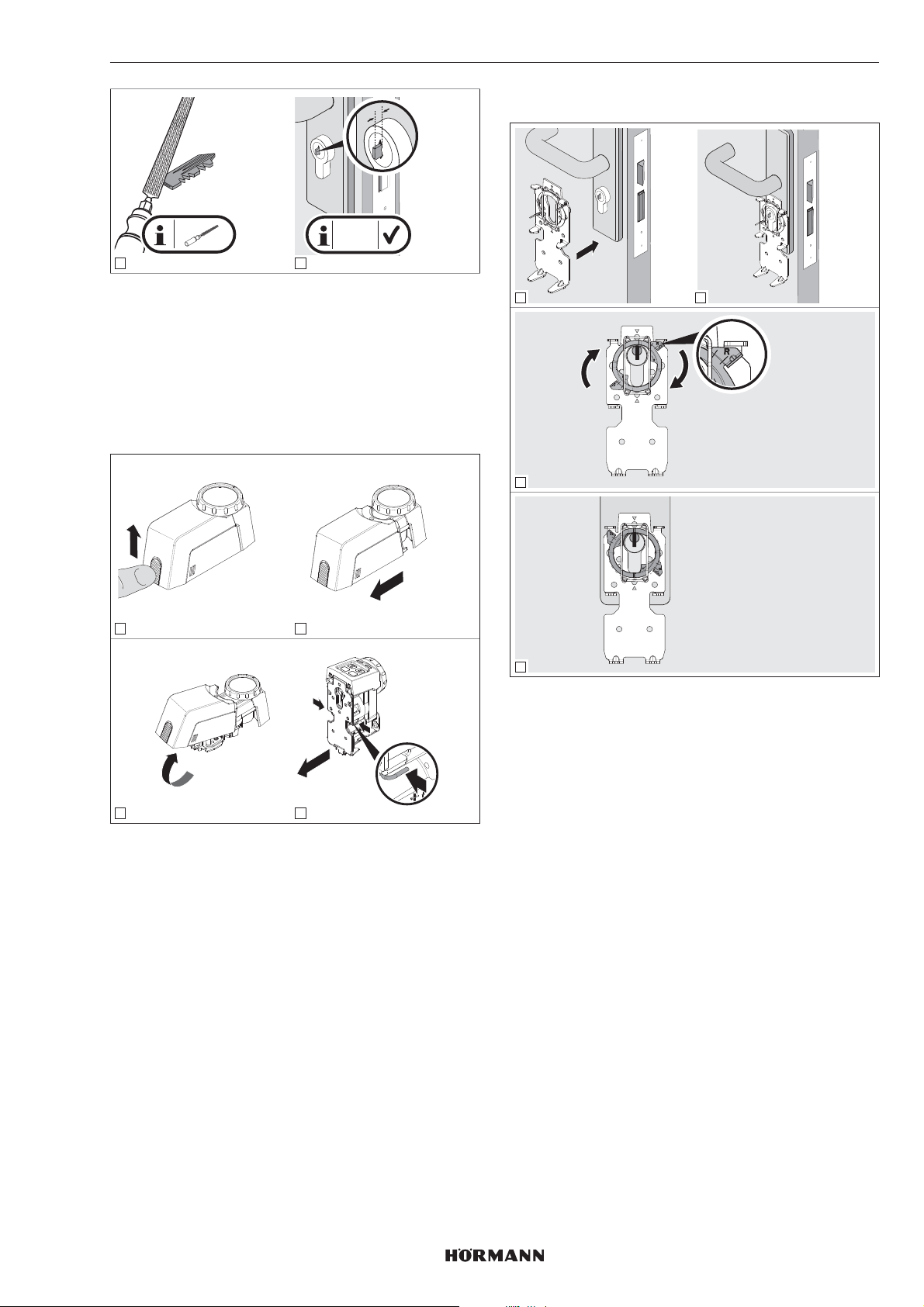
5.4 Fit retaining plate
1. Release the locking and hold it in the released
position.
2. Remove the operator cover.
3. Release the retaining plate.
4. Remove the retaining plate from the rear
oftheoperator.
ENGLISH
5.4.1 Clamp retaining plate
1 2
3
1 2
PRG
P
1.
press!
2.
3
4
There are four different options to fit the retaining plate,
which may be combined:
a. Clamp retaining plate
▶
See section5.4.1
b. Bond retaining plate
▶
See section5.4.2
c. Screw on retaining plate
▶
See section5.4.3
d. Retaining plate with rose escutcheon
screwconnection
▶
See section5.4.4
4
▶
Turn the clamping ring to the right up to the stop.
▶
Then check the profile cylinder. The cylinder must be in
a flawless mechanical condition and easy to move.
4555360 B0 / 42-2023/ DX
27
Page 28
ENGLISH
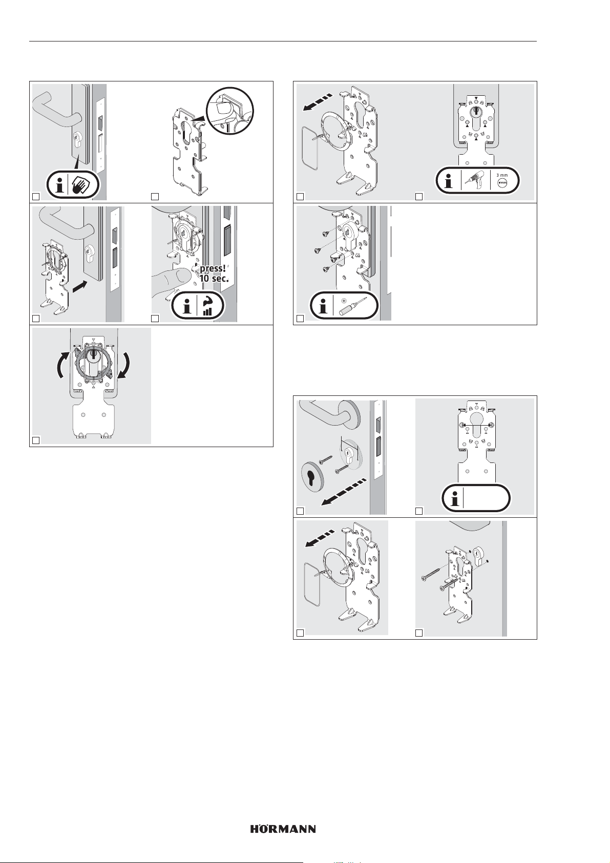
5.4.2 Bond retaining plate
1 2
3 4
5.4.3 Screw on retaining plate
1 2
3
▶
Use short self-tapping screws for fire-rated doors.
PH2
5
Cleaning the surfaces
▶
Use clean, lint-free and non-perfumed cleaning cloths.
▶
Use suitable cleaning agents. Do not use lipidrestoring household cleaners.
▶
Repeat the cleaning process until the surface isclean
and free of grease.
NOTE
Always use suitable cleaning agents and care products. It
is your responsibility to maintain an intact surface.
5.4.4 Retaining plate with rose escutcheon
screw connection
y
38 mm
y = 38 mm
1
3 4
▶
Make sure that you do not drill into the mortice lock.
Ifnecessary, shorten the screws.
2
28
4555360 B0 / 42-2023/ DX
Page 29
ENGLISH
6 Initial start-up
The door lock operator is ready for operation once
thebatteries have been inserted and the blue LED
hasgone out.
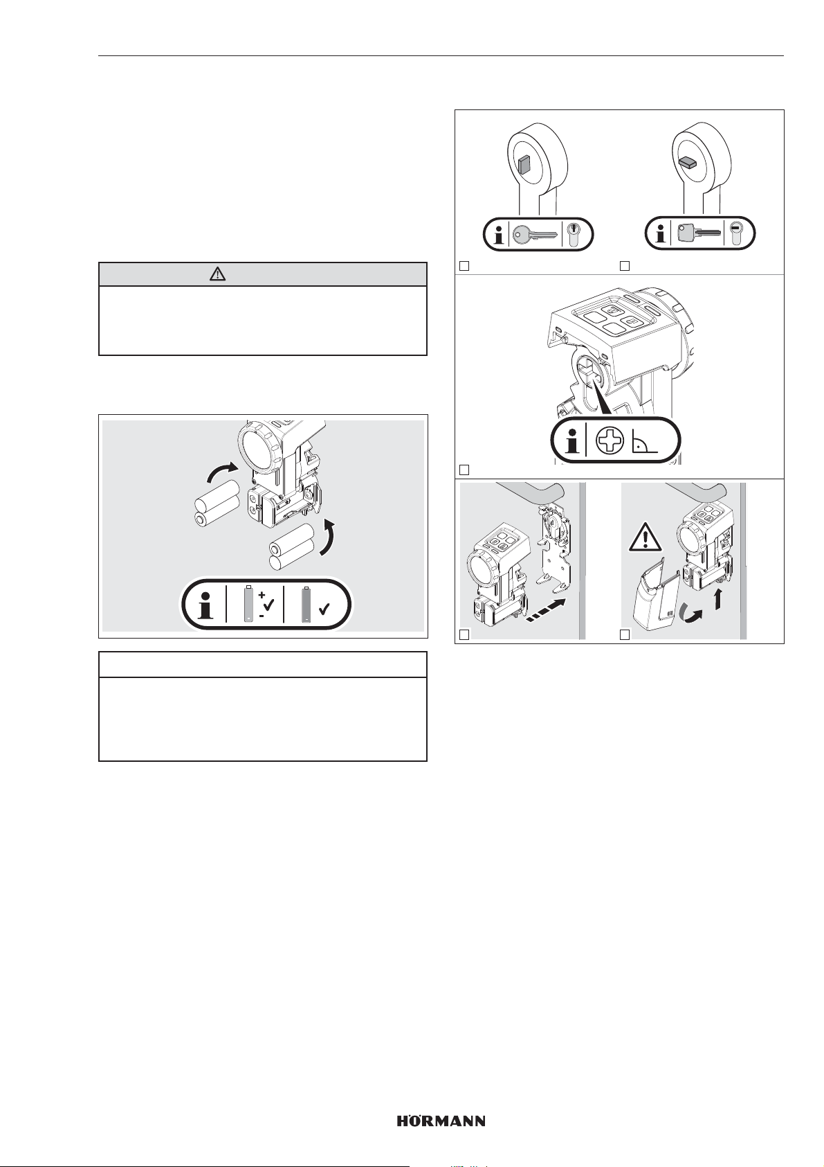
6.1 Inserting the batteries
To operate the door lock operator use:
• 4 x 1.5V battery, type AA (LR6), alkali-manganese
or
• 4 x 1.2V battery, type: AA (HR6), nickel metal hydride
WARNING
Risk of explosion due to incorrect battery type
There is the risk of explosion if the batteries are replaced
with an incorrect battery type.
▶
Only use the recommended battery type.
You may also use 4 AA batteries (HR6), 1.2 V, tooperate
the door lock operator.
6.2 Final work
1 2
3
PRG
P
90°
+
AA
+
ACCU
ACCU
ATTENTION
Destruction of the door lock operator due toleaking
batteries
Batteries may leak and destroy the door lock operator.
▶
Remove the batteries from the door lock operator if it
is out of use for a long period oftime.
P
PRG
P
PRG
2.
click!
4
5
1.
1. Pay attention to the proper position of the serrated key
and reversible key.
2. Align the cross slot on the rear of the operator
ataright angle with the hand wheel.
3. Insert the operator into the retaining plate console
– The operator will audibly engage.
4. Place the cover on the operator.
– The cover will audibly engage.
4555360 B0 / 42-2023/ DX
29
Page 30
ENGLISH
6.3 Teaching in the operator
PRGP
1
PRGP
ca. 3 sec. - 10 sec.
2
YE YE
press 3 sec.
YE YE
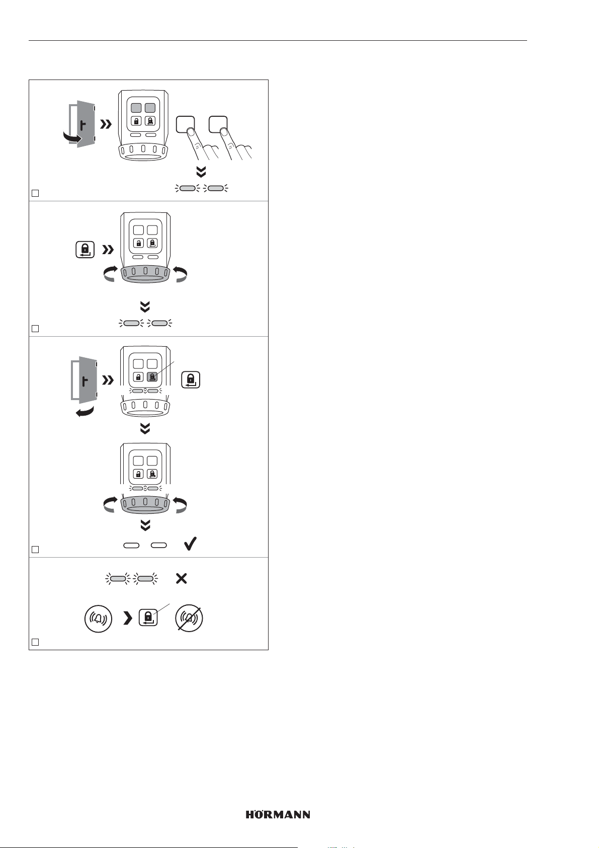
1. Simultaneously press and hold the P button and the
PRG button until both LEDs flash yellow.
2. Press the locking button.
The operator is taught in the travel distance of the
catch and bolt. The process is ended once the end-oftravel position is reached.
PRGP
+
3. Close the door.
4. Press the locking button.
The operator is taught in the required forces.
5. The operator has been taught in.
The LEDs go out.
NOTE
If the LEDs flash quickly and an acoustic signal isemitted,
the error cause must be remedied.
▶
See section10
6. Check the functions of the operator using the buttons
on the sensor field.
Timeout
If no button is pressed within 60seconds, the door lock
operator automatically switches to the operation mode.
The operator has not been taught in.
press
PRGP
YE YE
PRGP
YE YE
3
YE YE
press
=
4
The following prerequisites must be fulfilled in order
toteach in the operator.
• The operator has not been taught in.
• The operator is fitted to the door.
• The lock must be released, i.e. all bolts must
becompletely retracted.
• The door is open.
30
4555360 B0 / 42-2023 / DX
Page 31
ENGLISH
7 Functions
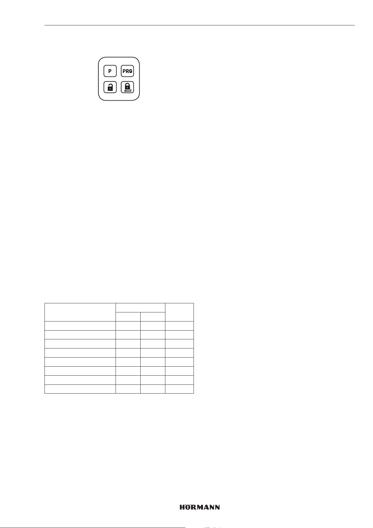
The functions of the door lock operator can be set using
the P button and the PRG button on the sensor field. Each
function has several parameters that enable additional
settings. Before initial start-up, allparameters are set to the
factory setting.
The functions may only be changed if the operator isat
rest.
NOTE
Please note that a change to the factory settings may
result in a shorter battery service life, for example ifthe
torque or speed is increased.
Set the functions and the respective parameters in
accordance with the local conditions and individual
adaptations.
7.1 1st menu level / functions
The functions of the door lock operator are stored inthe
1st menu level.
1. Press and hold the PRG button for 3seconds.
The door lock operator switches from normal
operation to the 1st menu level.
2. Select a function by briefly pressing the PRG button
several times.
Depending on the selected function, the respective
LED will be illuminated in the appropriate colour.
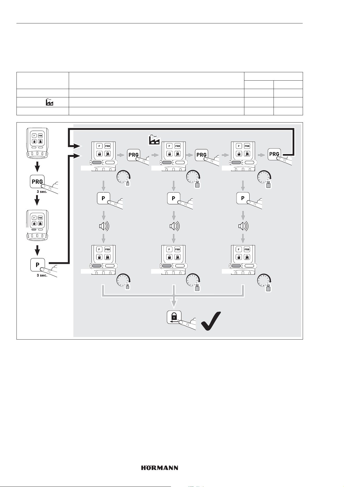
7.2 2nd menu level / parameters
The parameters for the functions from the 1st menu level
are stored in the 2nd menu level. If you want to set a
parameter, switch to the 2nd menu level.
1. Press and hold the P button for 3seconds.
The door lock operator will switch from the 1st menu
level to the 2nd menu level. The respective LED flashes
in the corresponding colour depending on the set
parameter.
2. Select a parameter by briefly pressing the PRG button
several times.
Depending on the selected function, the respective
LED will flash in the appropriate colour.
3. Activate the selected parameter by pressing the P
button for 3seconds.
If the parameter has been activated, the LEDs will
briefly go out and a signal tone is emitted. The LEDs
will then indicate the current parameters.
4. Briefly press the locking button
Press 1 × = 1stmenu level
Press 2 × = operation mode
To abort the parameter setting:
▶
Press the locking button 2 × or wait for thetimeout.
Timeout
If no button is pressed within 60seconds, the door lock
operator automatically switches to the operation mode.
Functions LED Section
Left Right
Torque GN 7.2.1
Speed RD 7.2.2
Latch hold time YE 7.2.3
Signal transmitter GN 7.2.4
Sensor field with buttons RD 7.2.5
Locking reduction YE 7.2.6
Comfort locking GN GN 7.2.7
Reset RD RD 7.2.8
GN = green, RD = red, YE = yellow
4555360 B0 / 42-2023 / DX
31
Page 32
ENGLISH
7.2.1 Torque
Depending on the door states or closing states, the torque of the latch pull can be set via parameters 1 – 3.
NOTE
Please note that an increase in torque will lead to a higher load on the key.
Parameter Settings LED
Left Right
1 Approx. 1.0Nm 1 × GN
2
3 Approx. 1.5Nm 3 × GN
Approx. 1.2Nm 2 × GN
GN
1x GN 2x GN 3x GN
ca. 1,0 Nm ca. 1,2 Nm
1x GN 2x GN 3x GN
ca. 1,0 Nm
Nm
3 sec.
Nm
1x
3 sec.
ca. 1,2 Nm
2 x
Nm
Nm
1 x
ca. 1,5 Nm
ca. 1,5 Nm
1 x
Nm
3 sec.
Nm
32
4555360 B0 / 42-2023 / DX
Page 33
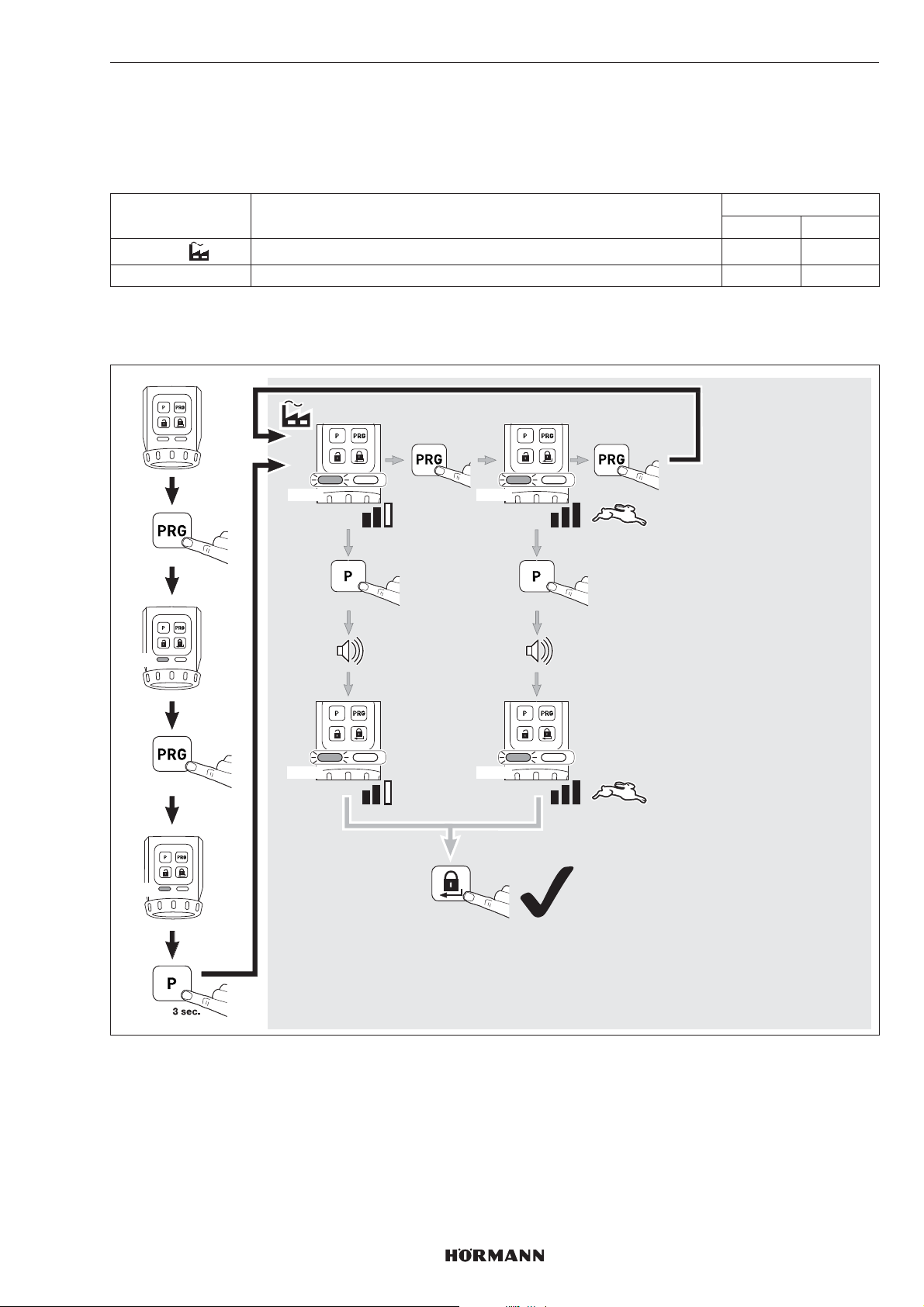
7.2.2 Speed
The speed for locking, unlocking and opening can be set via 2 parameters.
NOTE
Please note that an increase in speed will lead to a higher load on the key.
Parameter Settings LED
1
2 Maximum 2 × RD
TIP
We recommend keeping the automatic setting, as it automatically adjusts to the various door conditions.
Automatic 1 × RD
ENGLISH
Left Right
GN
RD
3 sec.
1 x
1x RD 2x RD
3 sec.
1x RD 2x RD
1x
2 x
1 x
3 sec.
4555360 B0 / 42-2023 / DX
33
Page 34
ENGLISH
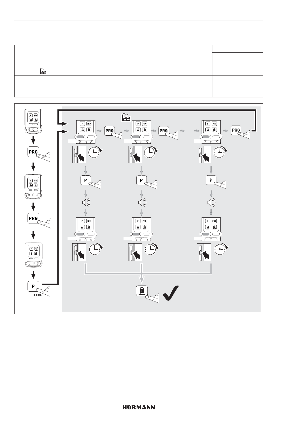
7.2.3 Latch hold time
The latch hold time enables setting the time in which the latch is held open in order to open the door.
Parameter Settings LED
1 Approx. 1second 1 × YE
2
3 Approx. 5seconds 3 × YE
4 Approx. 10seconds 4 × YE
5 Approx. 20seconds 5 × YE
Approx. 3seconds 2 × YE
Left Right
GN
YE
3 sec.
2 x
1x YE 2x YE 5x YE
1 sec.
3 sec.
1x YE 2x YE 5x YE
1 sec.
1x
3 sec.
3 sec.
3 sec.
1 x
…
1 x
20 sec.
3 sec.
20 sec.
34
2 x
4555360 B0 / 42-2023 / DX
Page 35
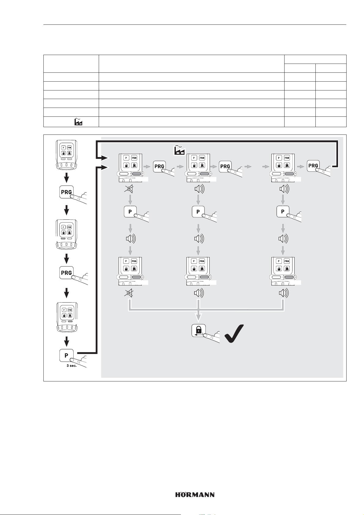
7.2.4 Signal transmitter
These parameters enable setting the signal characteristics.
Parameter Settings LED
1Off 1 × GN
2 Only buttons 2 × GN
3 Only end-of-travel positions 3 × GN
4 Only end-of-travel position locked 4 × GN
5 Buttons and end-of-travel position locked 5 × GN
6
Buttons and end-of-travel positions 6 × GN
ENGLISH
Left Right
GN
3 sec.
3 x
GN
1x GN 2x GN 6x GN
3 sec.
1x GN 2x GN 6x GN
1x
3 sec.
2 x
1 x
…
1 x
3 sec.
4555360 B0 / 42-2023 / DX
35
Page 36
ENGLISH
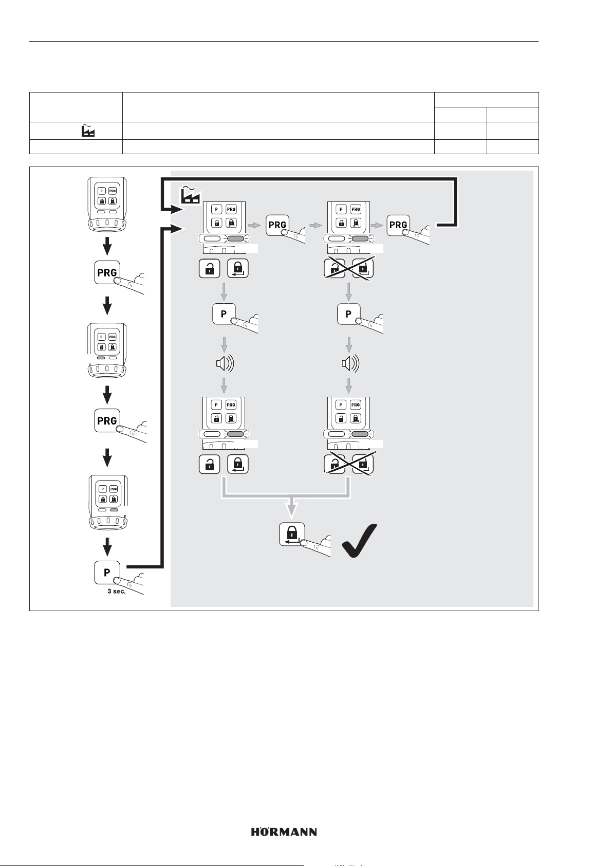
7.2.5 Sensor field with buttons
These parameters let you deactivate operation of the release button and the locking button.
Parameter Settings LED
1
2 Deactivate 2 × RD
Activate 1 × RD
Left Right
GN
3 sec.
4 x
RD
1x RD 2x RD
3 sec.
1x RD 2x RD
1x
1 x
3 sec.
36
2 x
4555360 B0 / 42-2023 / DX
Page 37
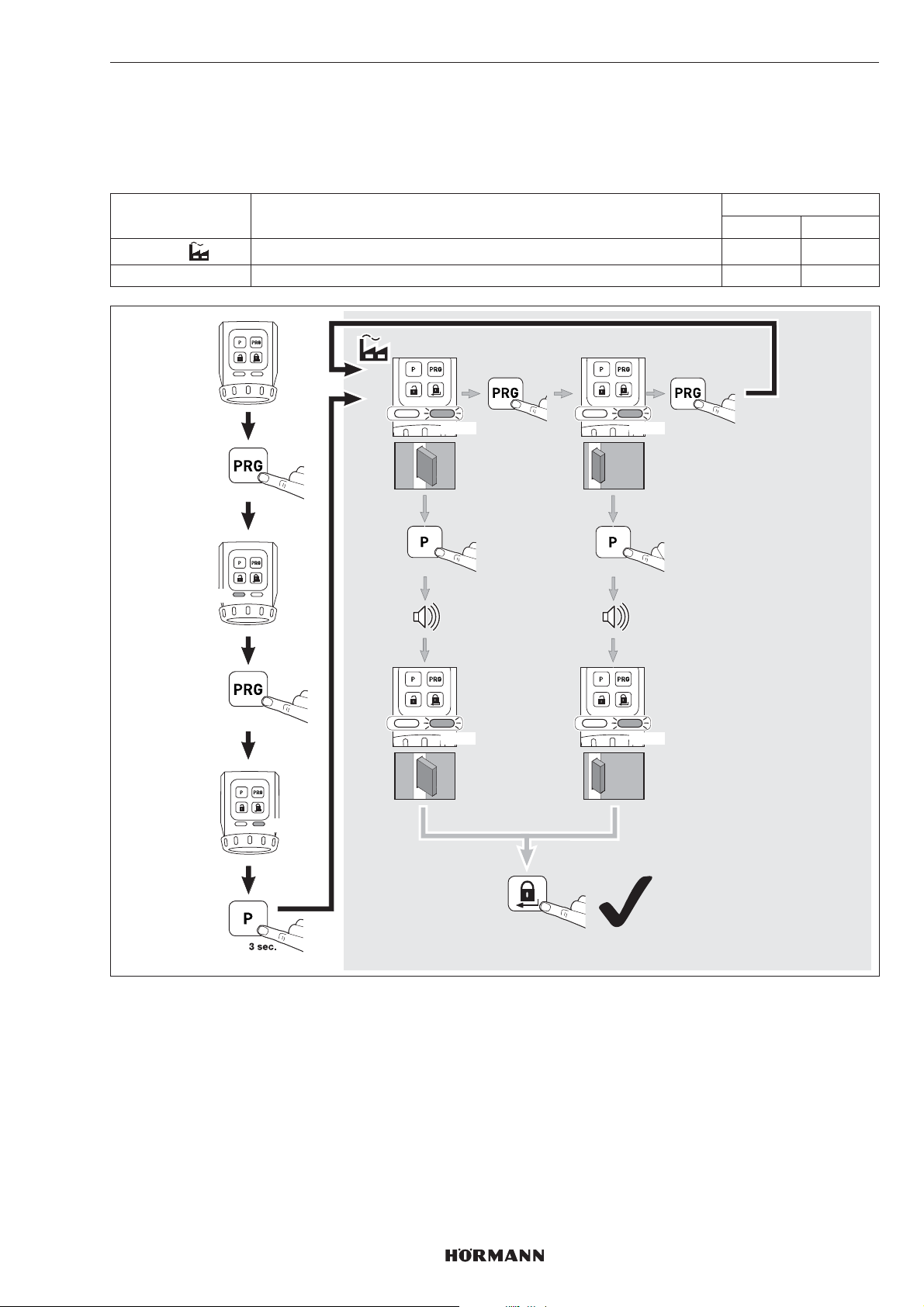
7.2.6 Locking reduction
These parameters let you reduce 2-turn locking to 1-turn locking.
NOTE
Due to safety reasons, we recommend using the factory setting.
Parameter Settings LED
1
2 Only one locking 2×YE
Automatic 1×YE
ENGLISH
Left Right
GN
3 sec.
5 x
YE
1x YE 2x YE
3 sec.
1x YE 2x YE
1x
1 x
1x
3 sec.
1x
4555360 B0 / 42-2023/ DX
2 x
37
Page 38
ENGLISH
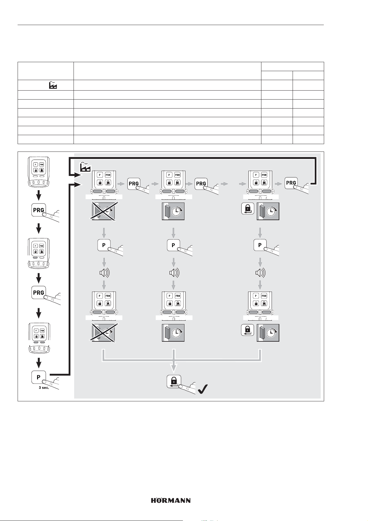
7.2.7 Comfort locking (automatic locking)
These parameters enable automatic locking after a preset period or after pressing a button and a preset period. Make sure
that the door is closed before the preset period elapses in order to ensure secure locking of the door.
Parameter Settings LED
Left Right
1
2 Approx. 30seconds after reaching the unlocked end-of-travel position 2× GN 2 ×GN
3 Approx. 60seconds after reaching the unlocked end-of-travel position 3× GN 3 ×GN
4 Approx. 120seconds after reaching the unlocked end-of-travel position 4× GN 4 ×GN
5 Approx. 10seconds after pressing the locking button 5 × GN 5× GN
6 Approx. 20seconds after pressing the locking button 6 × GN 6× GN
7 Approx. 30seconds after pressing the locking button 7 × GN 7× GN
Deactivated 1 × GN 1× GN
GN
GN
3 sec.
6 x
GN
1x GN 2x GN 7x GN
1x GN 2x GN 7x GN
1x GN 2x GN 7x GN
3 sec.
1x GN 2x GN 7x GN
1x
ca. 30 sec.
3 sec.
ca. 30 sec.
1 x
…
1 x
ca. 30 sec.
3 sec.
ca. 30 sec.
2 x
Brief deactivation of comfort locking (parameters 2, 3 and 4)
You can deactivate comfort locking.
▶
Press the PRG button.
Comfort locking is deactivated.
Comfort locking will be reactivated with the next locking command.
38
4555360 B0 / 42-2023/ DX
Page 39
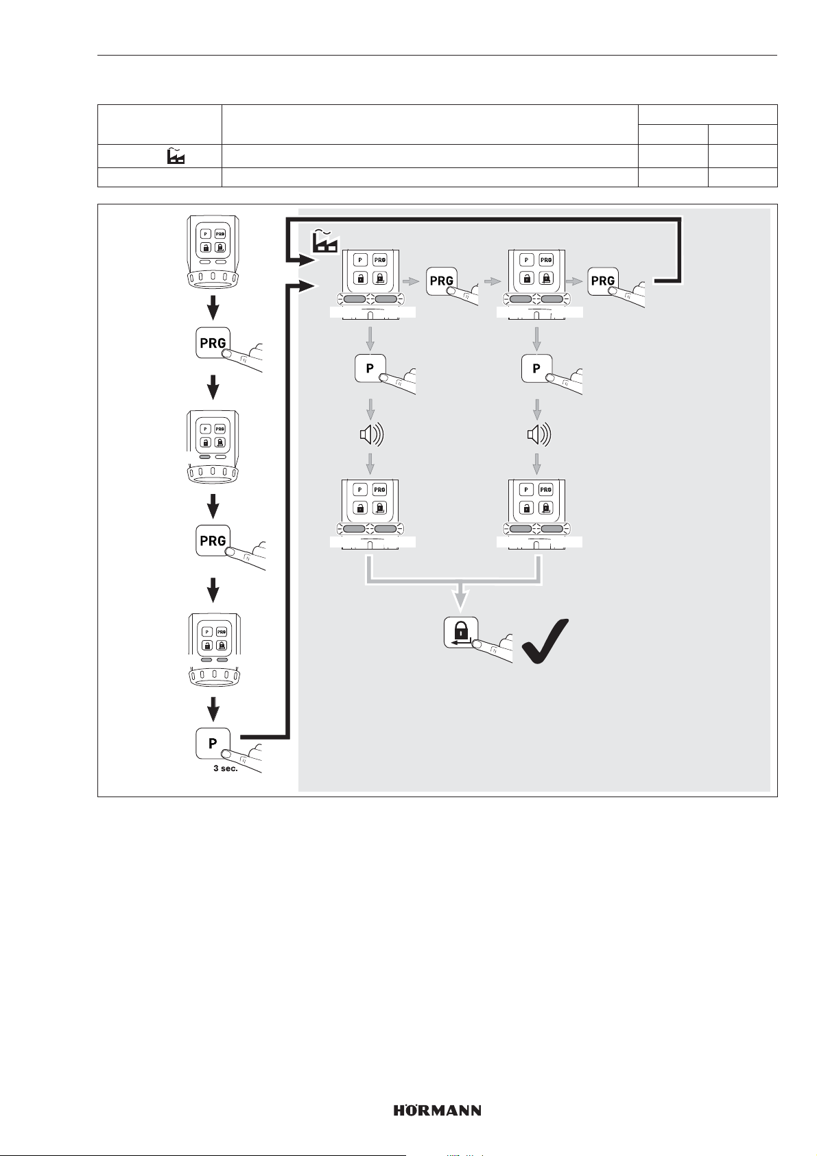
7.2.8 Reset
Parameter Settings LED
1
2 Learning runs and functions 2 × RD 2 ×RD
Only learning runs 1 × RD 1 ×RD
ENGLISH
Left Right
GN
RD
3 sec.
7 x
RD
1x RD 2x RD
1x RD 2x RD
1x RD 2x RD
3 sec.
1x RD 2x RD
1x
2 x
1 x
3 sec.
4555360 B0 / 42-2023/ DX
39
Page 40
ENGLISH
8 Radio
8.1 Integrated radio module
Max. 100radio codes can be transferred from the 4-button
hand transmitter HSE 4-SK-BS or security hand transmitter
HSSE 4-SK and distributed to the existing channels. If
more than 100 radio codes are transferred, the first ones to
be taught in will be deleted.
The radio codes from other transmitters* cannot be taught
in on the door lock operator. However, the 4-button hand
transmitter HSE 4-SK-BS and the security hand transmitter
HSSE 4-SK can inherit theirradio codes to other BiSecur
transmitters*.
8.2 Hand transmitters
The door lock operator comes with 4-button hand
transmitter HSE4-SK, whose radio codes must be taught
in on the door lock operator.
▶
See section8.3
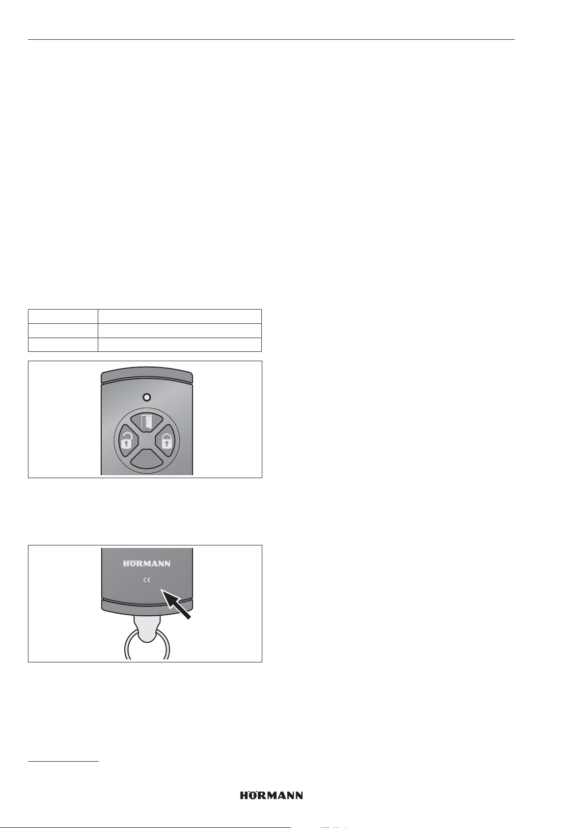
Assigning buttons
Left Release
Top Open
Right Lock
8.3 Teaching in the radio codes of hand
transmitter HSE 4-SK
When teaching in the radio codes of hand transmitter
HSE4SK, all 3 channels are simultaneously taught in.
1. Briefly press the P button on the door lock operator
1 × .
– The right LED will flash slowly in blue.
2. Hold the hand transmitter in front of the door lock
operator.
3. Press and hold the Open button on the hand
transmitter.
– The LED is illuminated blue for 2 seconds and then
goes out.
– After 5 seconds, the LED alternates flashing inred
and blue.
– The hand transmitter sends the radio codes.
4. Once the radio codes have been detected, the LED on
the operator will flash quickly in blue.
– After 2 seconds, the LED goes out.
5. Release the hand transmitter button.
6. Press the P button to conclude the teach-in process.
The radio codes of the hand transmitter have been
taught in.
8.4 Teaching in the radio codes of security
hand transmitter HSSE 4-SK
When teaching in the radio codes of security hand
transmitter HSSE 4-SK, all 3 channels are simultaneously
taught in.
No further hand transmitters HSE4-SK or HSSE4-SK with
the index specification -3 can be taught in on the operator.
Inheriting to other transmitters* is only possible via a
copying procedure from the security hand transmitter.
NOTE
For your own safety, we recommend deleting the
previously taught-in radio codes on the door lock operator
if you
NOTE
It is not possible to inherit radio codes from hand
transmitter HSE4SK to other transmitters* if there isno
index or if the index specification is -1 or -2.
HSE4-868-BS
0498-2
* e.g. hand transmitter, gateway
– teach in a security hand transmitter.
– have performed a device reset on a security hand
transmitter.
▶
See section8.3
40
4555360 B0 / 42-2023 / DX
Page 41

ENGLISH
The radio codes of the security hand transmitter have
been taught in.
NOTE
You have 25 seconds to inherit / transmit the radio code. If
inheriting/transmitting the code was not successful within
this period of time, repeat the process.
8.5 Deleting all radio codes
You cannot delete the radio codes for individual transmitter
buttons or individual functions.
▶
Press and hold the P button.
– The LED slowly flashes in blue for 5 seconds.
– The LED flashes rapidly in blue for 2 seconds.
– The LED goes out.
All radio codes have been deleted.
8.6 Sleep mode
If sleep mode is activated
– the operator cannot be operated via radio,
– the battery service life is increased.
8.6.1 Activating sleep mode
▶
Press the locking button on the sensor field for
5seconds.
The operator goes into the locked end-of-travel
position, sleep mode is activated and the right LED
flashes 5 × in blue.
NOTE
If the operator is already in the locked end-of-travel
position, sleep mode will be activated immediately.
9 Operation
9.1 Operation via sensor field
For operation via the sensor field, use the release /open
and lock buttons.
9.2 Operation via radio
NOTE
If the radio code of the hand transmitter button isinherited
from another hand transmitter, press thehand transmitter
button twice when operating itthe first time.
9.3 Operation via hand wheel / key
Operation via hand wheel / key is only intended
foremergencies.
NOTE
After unlocking with the hand wheel or a key, an operator
reference run will automatically be performed during the
next operation. The left LED will then flash in red.
10 Error states
10.1 Learning runs
Message Cause Remedy
Acoustic signal
(60sec.) and both
LEDs flash in
yellow
Error during the
learning run
Press a button on
the sensor field
8.6.2 Deactivating sleep mode
▶
Press the release button or locking button
onthesensor field.
Sleep mode is deactivated and the right LED
isilluminated in blue for 2seconds.
NOTE
Turning the hand wheel or key also deactivates
sleepmode.
10.2 Normal operation
Message Cause Remedy
Acoustic signal for
3sec., then the left
LED flashes in
yellow for 3sec.
Acoustic signal
(60sec.) and the
left LED flashes in
yellow
Acoustic signal
(60sec.) and the
left LED flashes in
red
Low battery
status
Error during
arun /
reference run
Error during
areference run
Replace all
batteries
simultaneously
Press a button on
the sensor field
New travel
command via
radio (only open
or release)
Press a button on
the sensor field
New travel
command via
radio (only open
or release)
4555360 B0 / 42-2023 / DX
41
Page 42
ENGLISH
11 Cleaning
ATTENTION
Damage to the door lock operator due to improper
cleaning
Cleaning the door lock operator with unsuitable cleaning
agents can damage the housing, as well as the buttons.
▶
Clean the door lock operator with a clean, soft, damp
cloth.
12 Disposal
Dispose of the packaging sorted by materials
Electrical and electronic devices must be returned
to the appropriate recycling facilities.
Dispose of the batteries separately. Each consumer
is legally required to leave batteries with a collection
point in their community, their district, or with a
trader.
13 Technical data
Door lock operator
Model SmartKey
Frequency 868MHz
Transmitting power Max. 10 mW (EIRP)
Power supply • 4 x 1.5V battery, type AA
(LR6), alkali-manganese
or
• 4 x 1.2V battery, type: AA
(HR6), nickel metal hydride
Perm. ambient
temperature
Protection category IP20
0°C to +40°C
14 EU and UK Declaration of
Conformity
Hörmann KG Verkaufsgesellschaft and Hörmann UK Ltd.
herewith declares that the radio equipment type radio door
lock operator Smartkey complies with the EU Directive
2014/53/EU and the UK Regulations 2017 No. 1206.
The complete text of the EU Declaration of Conformity and
of the UK Declaration of Conformity can be found on the
following website:
42
www.hoermann-docs.com/277127
4555360 B0 / 42-2023 / DX
Page 43

Table des matières
1 A propos de ce mode d’emploi ......................44
1.1 Symboles utilisés ...............................................44
2 Consignes de sécurité ....................................44
2.1 Utilisation appropriée ........................................44
2.2 Utilisation non appropriée .................................44
2.3 Consignes de sécurité concernant
lefonctionnement ..............................................44
3 Matériel livré .....................................................44
4 Description produit ..........................................45
5 Montage ...........................................................46
5.1 Contrôle des caractéristiques de la porte .........46
5.2 Vérifier la porte et le cylindre profilé ..................46
5.3 Scier la tête de clé .............................................46
5.4 Monter la tôle de support ..................................47
6 Mise en service ................................................49
6.1 Insérer les piles ..................................................49
6.2 Etapes finales ....................................................49
6.3 Apprentissage de la motorisation ......................50
7 Fonctions ..........................................................51
7.1 Premier niveau de menu / Fonctions..................51
7.2 Deuxième niveau de menu / Paramètres ...........51
8 Système radio ..................................................60
8.1 Module radio intégré .........................................60
8.2 Emetteur ............................................................60
8.3 Apprentissage des codes radio d’unémetteur
HSE 4-SK ..........................................................60
8.4 Apprentissage des codes radio d’unémetteur de
sécurité HSSE 4-SK ..........................................60
8.5 Suppression de tous les codes radio ................61
8.6 Mode veille ........................................................61
9 Fonctionnement ...............................................61
9.1 Commande par panneau tactile ........................61
9.2 Commande par radio ........................................61
9.3 Commande par molette / clé..............................61
10 Conditions de défaut .......................................61
10.1 Trajets d’apprentissage .....................................61
10.2 Fonctionnement normal ....................................61
11 Nettoyage .........................................................62
12 Elimination ........................................................62
13 Données techniques ........................................62
14 Déclaration de conformité UE ........................62
FRANÇAIS
Toute transmission ou reproduction dece document, toute exploitation
oucommunication de son contenu sont interdites, sauf autorisation
expresse. Tout manquement à cette règle est illicite et expose son auteur au
versement dedommages et intérêts. Tous droits réservés en cas de dépôt
d’un brevet, d’un modèle d’utilité ou d’agrément. Sous réserve de
modifications.
4555360 B0 / 42-2023 / DX
43
Page 44
FRANÇAIS
1 A propos de ce mode d’emploi
Les présentes instructions comprennent des informations
importantes sur le produit, notamment des consignes de
sécurité et des avertissements.
▶
Veuillez les lire entièrement et attentivement.
▶
Conservez soigneusement les présentes instructions.
AVIS
Respectez toutes les dispositions, normes et directives de
sécurité applicables sur le site d’exploitation du SmartKey.
1.1 Symboles utilisés
Remarque importante
Disposition ou procédure autorisée
Disposition ou procédure interdite
2.2 Utilisation non appropriée
La motorisation de serrure de porte ne doit pas être
utilisée:
– sur des portes coupe-feu sans justificatif
– sur des portes d’issue de secours
2.3 Consignes de sécurité concernant
lefonctionnement
AVERTISSEMENT
Danger en cas d’urgence dû à une porte verrouillée
dans un immeuble collectif
Dans une situation de panique et d’évacuation
dubâtiment, une porte verrouillée peut être unobstacle
mortel.
▶
N’utilisez pas la motorisation de serrure sur laporte
d’entrée principale d’un immeuble collectif.
ATTENTION
Altération du fonctionnement due à des influences
environnementales
En cas de non-respect, le fonctionnement
peutêtrealtéré!
Température ambiante admise: 0°C à +40°C.
Réglage d’usine
2 Consignes de sécurité
2.1 Utilisation appropriée
La motorisation de serrure de porte est une unité
– de verrouillage et déverrouillage à commande
motorisée.
– pour les portes avec un verrouillage à maximum
2tours de clés (double-verrouillage).
– pour les intérieurs secs.
– pour les portes coupe-feu Hörmann T30 / EI
tôle d’acier avec ferrure à rosette ronde des séries
H3OD, STS30 / STU30, D65, STS / STU.
Pour les portes en acier avec ferrure à plaque courte,
utilisez une plaque d’adaptation en acier inoxydable.
Dans la motorisation, la clé est insérée dans un logement à
partir duquel le cylindre profilé peut être verrouillé,
déverrouillé et ouvert. L’impulsion pour la motorisation est
fournie, par exemple, par:
– le panneau à touches tactiles,
– un émetteur,
– un lecteur digital sans fil,
– l’appliHörmann Homee.
Tout autre type d’utilisation est interdit. Le fabricant décline
toute responsabilité en cas de dommages provenant d’une
utilisation inappropriée ou incorrecte.
30 en
2
▶
Après la programmation ou l’extension du système
radio, procédez toujours à un essai de fonctionnement.
▶
Pour la mise en service ou l’extension du système
radio, utilisez exclusivement des pièces d’origine.
• Les impératifs locaux peuvent exercer une influence
sur la portée du système radio.
3 Matériel livré
• Motorisation de serrure de porte SmartKey
• Tôle de support
• Emetteur HSE4-SK-BS
• 4 × pile 1,5V, type:AA (LR6), alcaline au manganèse
• Accessoires de fixation
• Instructions succinctes
44
4555360 B0 / 42-2023 / DX
Page 45
4 Description produit
1
FRANÇAIS
8
7
6
5
4
P
PRG
3
2
9
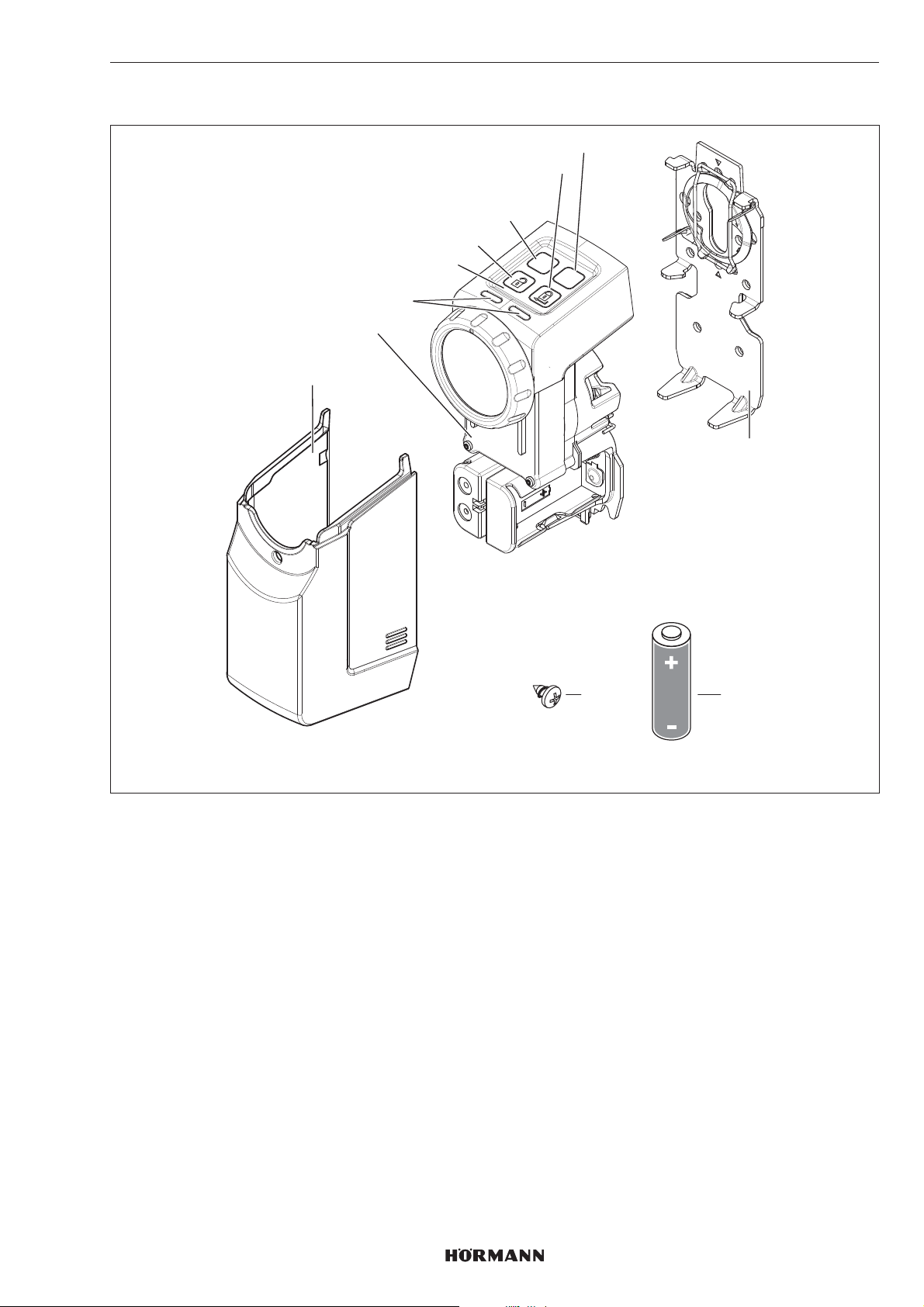
1 Capot de protection
2 Motorisation
3 LED (gauche / droite), multicolore
4 Panneau à touches tactiles
5 Touche de déverrouillage
6 ToucheP
7 Touche de verrouillage
8 Touche PRG
9 Tôle de support
10 Pile1,5V, type :AA (LR6), alcaline au manganèse (4 x)
11 Vis, 4,2 × 9,5mm (4 ×
11
10
AA
4555360 B0 / 42-2023 / DX
45
Page 46
FRANÇAIS
5 Montage
La motorisation de serrure de porte nécessite l’insertion
permanente d’une clé dans le cylindre profilé. Le cylindre
doit être:
– un cylindre profilé Euro selon la norme DIN18252 et
DINEN1303.
– doté d’une fonction de secours et de danger
permettant d’ouvrir le cylindre côté extérieur avec
une autre clé lorsqu’une clé est engagée côté
intérieur.
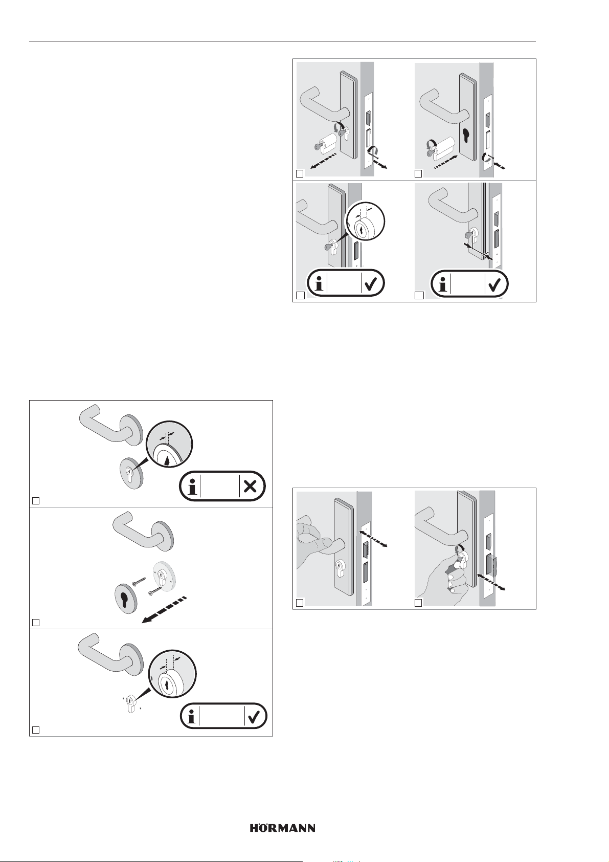
5.1 Contrôle des caractéristiques de la
porte
Le cylindre doit être en saillie de 7 à 12mm sur lecôté
intérieur de la porte.
▶
Remplacez le cylindre:
– s’il n’est pas doté d’une fonction de secours etde
danger
– la saillie du cylindre est inférieure à 7mm
CONSEIL
Nous recommandons, dans la mesure du possible,
unmontage direct de la motorisation sur le panneau de
porte.
La cote entre l’axe du trou de la serrure et l’arête extérieure
de la porte / l’huisserie doit être d’au minimum 35mm,
sous peine de ne pas pouvoir ouvrir la porte après le
montage.
X
X < 7 mm
1
2.
3.
4
X = 7-12
6
mm
1.
X
1.
2.
5
Y ≥ 35
7
mm
3.
Y
5.2 Vérifier la porte et le cylindre profilé
La porte et le cylindre profilé doivent se trouver dans un
état mécanique irréprochable et se déplacer librement.
▶
Vérifiez le réglage de votre porte et du cylindre avant
de monter la motorisation de serrure deporte.
▶
Vérifiez si la serrure de votre porte a un verrouillage à 1
ou 2tours.
▶
Vérifiez si les mêmes verrouillages (à 1 ou 2tours) sont
possibles avec la porte ouverte et fermée. Si,avec un
verrouillage à 2 tours et à porte fermée, seul un
verrouillage à 1tour est possible, les trajets
d’apprentissage de l’effort et de course doivent être
appris à porte fermée.
46
check!
1
2
2
check!
5.3 Scier la tête de clé
X
X = 7-12 mm
3
1. Déverrouillez la porte.
2. Mesurez 4 à 7mm entre le cylindre profilé etlatête de
clé.
3. Sciez la tête de clé.
4. Ebavurez la coupe de scie.
5. Réinsérez la clé dans le cylindre.
4555360 B0 / 42-2023/ DX
Page 47
FRANÇAIS
y
y = 4-7
mm
1 2
y
y = 4-7
mm
3
4
5.4 Monter la tôle de support
1. Déverrouillez le verrouillage et maintenez-le enposition
déverrouillée.
2. Retirez le capot de protection de la motorisation.
3. Déverrouillez la tôle de support.
4. Retirez la tôle de support du côté arrière
delamotorisation.
5.4.1 Serrer la tôle de support
1 2
3
1 2
PRG
P
1.
press!
2.
3
4
La tôle de support peut être montée de quatre manières
différentes qui peuvent être combinées entreelles:
a. Serrer la tôle de support
▶
Voir chapitre5.4.1
b. Coller la tôle de support
▶
Voir chapitre5.4.2
c. Visser la tôle de support
▶
Voir chapitre5.4.3
d. Tôle de support à vissage de rosette
▶
Voir chapitre5.4.4
4
▶
Tournez la bague de serrage vers la droite jusqu’à
labutée.
▶
Contrôlez ensuite le cylindre profilé. Le cylindre doit se
trouver dans un état mécanique irréprochable
etsedéplacer librement.
4555360 B0 / 42-2023/ DX
47
Page 48
FRANÇAIS
5.4.2 Coller la tôle de support
1 2
3 4
5.4.3 Visser la tôle de support
1 2
3
▶
Pour les portes coupe-feu, utilisez de courtes vis à
tôle.
PH2
5
Nettoyage des surfaces
▶
Utilisez exclusivement des chiffons propres,
sansparfum et ne peluchant pas.
▶
Utilisez des produits nettoyants adaptés et non des
détergents ménagers laissant un film gras.
▶
Répétez l’opération de nettoyage jusqu’à ce que la
surface soit propre et exempte de toute trace de gras.
REMARQUE
Utilisez toujours des produits de nettoyage et d’entretien
appropriés. Vous êtes seul responsable del’intégrité de la
surface.
5.4.4 Tôle de support à vissage de rosette
y
38 mm
y = 38 mm
1
3 4
▶
Veillez à ne pas percer dans la serrure encastrée.
Lecas échéant, raccourcissez les vis.
2
48
4555360 B0 / 42-2023/ DX
Page 49
FRANÇAIS
6 Mise en service
La motorisation de serrure de porte est opérationnelle dès
que les piles ont été insérées et que la LED bleue est
éteinte.
6.1 Insérer les piles
Pour le fonctionnement de la motorisation de serrure de
porte, utilisez:
• 4piles de 1,5V, type AA (LR6), alcaline au manganèse
ou
• 4piles rechargeables de 1,2V, type AA (HR6), nickelhydrure métallique
AVERTISSEMENT
Risque d’explosion en cas de type de pile incorrect
Le remplacement des piles par un type incorrect peut
causer un risque d’explosion.
▶
Utilisez uniquement le type de pile recommandé.
6.2 Etapes finales
1 2
3
PRG
P
90°
+
AA
+
ACCU
ACCU
ATTENTION
Destruction de la motorisation de serrure deporte
due à une fuite des piles
Les piles peuvent fuir et détruire la motorisation
deserrure de porte.
▶
Si vous n’utilisez pas la motorisation de serrure de
porte sur une période prolongée, retirez-en les piles.
P
PRG
P
PRG
2.
click!
4
5
1.
1. Veillez à la position correspondante de la clé dentée et
de la clé réversible.
2. A l’aide de la molette, alignez la fente cruciforme
àangle droit sur le côté arrière de la motorisation.
3. Montez la motorisation sur la plaque de maintien.
– La motorisation s’enclenche de manière audible.
4. Montez le capot de protection sur la motorisation.
– Le capot de protection s’enclenche de manière
audible.
4555360 B0 / 42-2023/ DX
49
Page 50
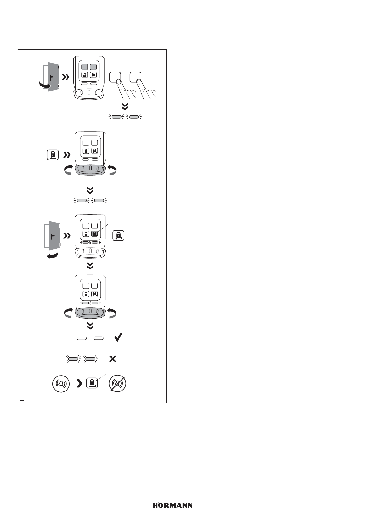
FRANÇAIS
6.3 Apprentissage de la motorisation
PRGP
1
PRGP
ca. 3 sec. - 10 sec.
2
YE YE
press 3 sec.
PRGP
+
YE YE
1. Appuyez simultanément sur la touche P et la touche
PRG et maintenez-les enfoncées jusqu’à ce que les
deux LED clignotent en jaune.
2. Appuyez sur la touche de verrouillage.
La motorisation apprend les trajets de course
duverrou et du pêne. La procédure est terminée une
fois les positions finales atteintes.
3. Fermez la porte.
4. Appuyez sur la touche de verrouillage.
La motorisation apprend les efforts requis.
5. La motorisation est apprise.
Les LED s’éteignent.
REMARQUE
Si les LED clignotent rapidement et qu’un signal sonore
retentit, la cause du défaut doit être éliminée.
▶
Voir chapitre10
6. Vérifiez les fonctions de la motorisation via les touches
du panneau tactile.
Temporisation
Si aucune touche n’est enfoncée dans un intervalle
de60secondes, la motorisation de serrure de porte
repasse automatiquement en mode de fonctionnement.
La motorisation n’est pas apprise.
press
PRGP
YE YE
PRGP
YE YE
3
YE YE
press
=
4
Pour l’apprentissage de la motorisation, les conditions
suivantes doivent être remplies:
• La motorisation n’est pas apprise.
• La motorisation est montée sur la porte.
• La serrure doit être déverrouillée: tous les pênes
doivent être entièrement rétractés.
• La porte est ouverte.
50
4555360 B0 / 42-2023 / DX
Page 51
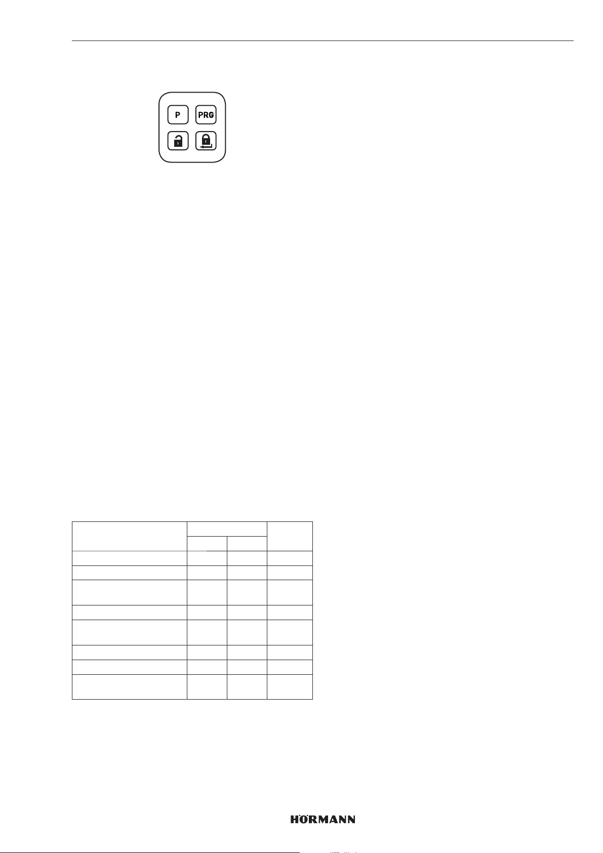
FRANÇAIS
7 Fonctions
Les fonctions de la motorisation de serrure de porte
peuvent être réglées à l’aide de la touche P et de la touche
PRG du panneau tactile. Chaque fonction possède
plusieurs paramètres permettant de procéder à des
réglages supplémentaires. Avant la toute première mise en
service, tous les paramètres doivent être sur réglage
d’usine.
Les fonctions peuvent uniquement être modifiées lorsque
la motorisation est au repos.
REMARQUE
Veuillez noter qu’une modification du réglage d’usine peut
diminuer la durée de vie de la pile, par exemple lors d’une
augmentation du couple de rotation ou dela vitesse.
Les fonctions et les divers paramètres doivent être réglés
en tenant compte des conditions sur site et des
adaptations individuelles.
7.1 Premier niveau de menu / Fonctions
Les fonctions de la motorisation de serrure de porte sont
stockées dans le premier niveau de menu.
1. Appuyez sur la touche PRG et maintenez-la enfoncée
pendant 3secondes.
La motorisation de serrure de porte passe
dufonctionnement normal au premier niveau demenu.
2. Sélectionnez une fonction en appuyant plusieurs fois
brièvement sur la touche PRG.
Selon la fonction sélectionnée, la LED respective
s’allume dans la couleur correspondante.
7.2 Deuxième niveau de menu / Paramètres
Les paramètres des fonctions du premier niveau demenu
sont stockées dans le deuxième niveau demenu. Si vous
souhaitez régler un paramètre, passez au deuxième niveau
de menu.
1. Appuyez sur la touche P et maintenez-la enfoncée
pendant 3secondes.
La motorisation de serrure de porte passe du premier
au deuxième niveau de menu. Selon leparamètre
réglé, la LED respective clignote àlacouleur
correspondante.
2. Sélectionnez un paramètre en appuyant plusieurs fois
brièvement sur la touche PRG.
Selon la fonction sélectionnée, la LED respective
clignote à la couleur correspondante.
3. Activez le paramètre sélectionné en maintenant
latouche P enfoncée pendant 3secondes.
Lorsque le paramètre a été activé, les LED s’éteignent
brièvement et un signal sonore retentit. Les LED
indiquent ensuite le paramètre actuel.
4. Appuyez brièvement sur la touche de verrouillage:
1pression = premierniveau de menu
2pressions = mode de fonctionnement
Pour annuler le réglage des paramètres:
▶
Appuyez 2 × sur la touche de verrouillage ouattendez
la fin de la temporisation.
Temporisation
Si aucune touche n’est enfoncée dans un intervalle
de60secondes, la motorisation de serrure
deporterepasse automatiquement en mode
defonctionnement.
Fonctions LED Chapitre
Gauche Droite
Couple GN 7.2.1
Vitesse RD 7.2.2
Durée de maintien
dupêne
Signaleur GN 7.2.4
Panneau à touches
tactiles
Réduction duverrouillage YE 7.2.6
Verrouillage de confort GN GN 7.2.7
Réinitialisation
del’appareil
GN = vert, RD = rouge, YE = jaune
4555360 B0 / 42-2023 / DX
YE 7.2.3
RD 7.2.5
RD RD 7.2.8
51
Page 52
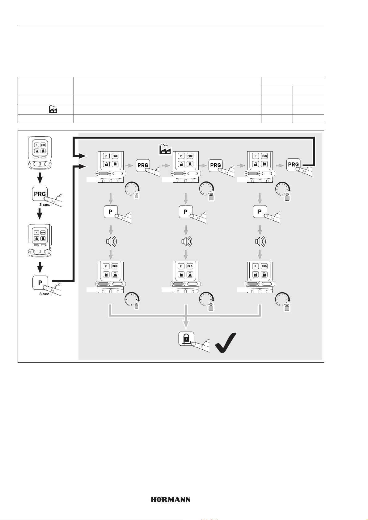
FRANÇAIS
7.2.1 Couple de rotation
Selon l’état des portes et des fermetures, le couple de rétractation de pêne peut être réglé via les paramètres 1 – 3.
REMARQUE
Veuillez noter que l’augmentation du couple entraîne une sollicitation plus élevée de la clé.
Paramètres Réglages LED
Gauche Droite
1 Env. 1,0Nm 1 × GN
2
3 Env. 1,5Nm 3 × GN
Env. 1,2Nm 2 × GN
GN
1x GN 2x GN 3x GN
ca. 1,0 Nm ca. 1,2 Nm
1x GN 2x GN 3x GN
ca. 1,0 Nm
Nm
3 sec.
Nm
1x
3 sec.
ca. 1,2 Nm
2 x
Nm
Nm
1 x
ca. 1,5 Nm
ca. 1,5 Nm
1 x
Nm
3 sec.
Nm
52
4555360 B0 / 42-2023 / DX
Page 53
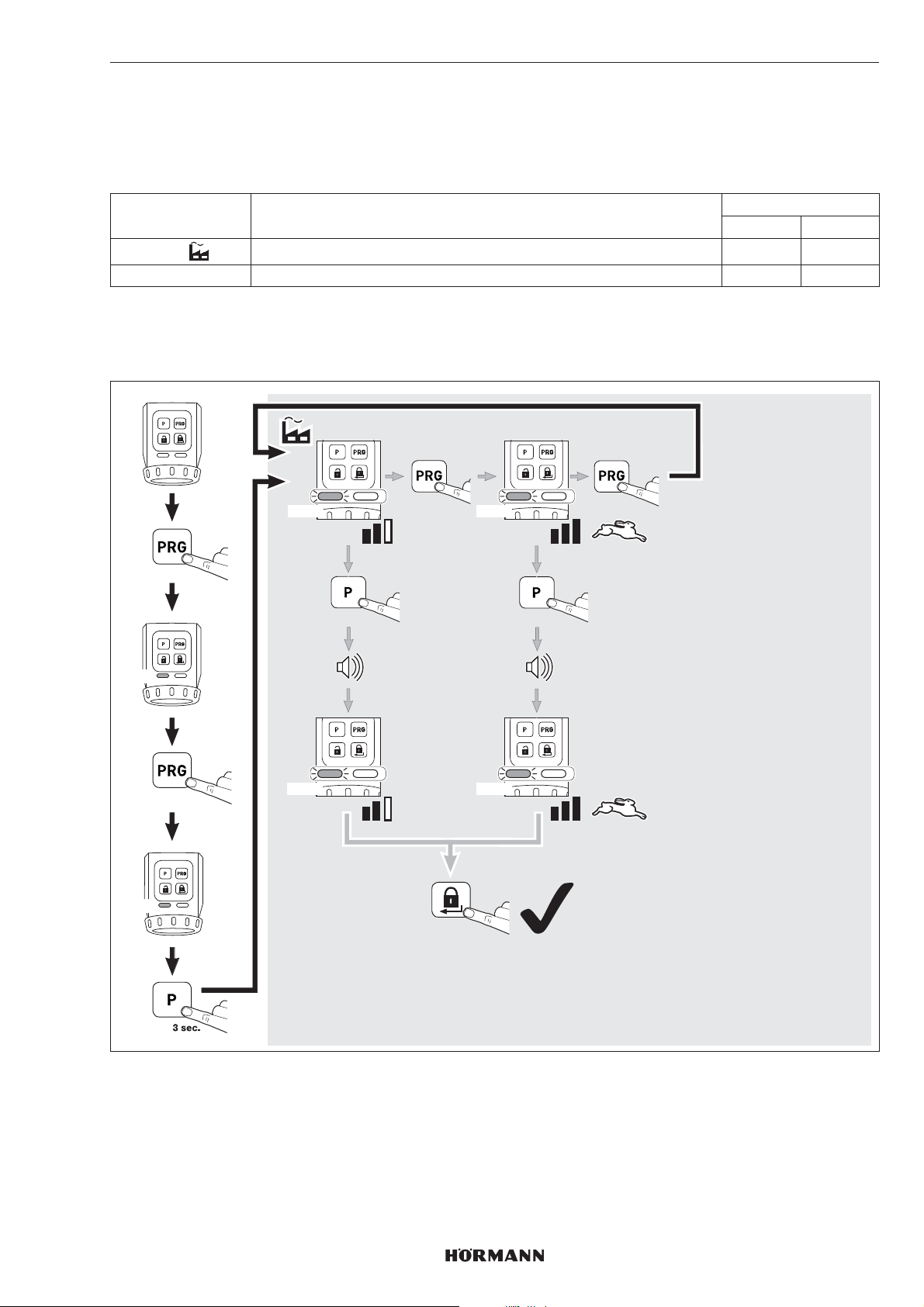
FRANÇAIS
7.2.2 Vitesse
La vitesse de verrouillage, de déverrouillage et d’ouverture peut être réglée par 2paramètres.
REMARQUE
Veuillez noter que l’augmentation de la vitesse entraîne une sollicitation plus élevée de la clé.
Paramètres Réglages LED
Gauche Droite
1
2 Maximum 2 × RD
CONSEIL
Nous vous recommandons de conserver le réglage automatique car il s’adapte automatiquement aux différentes conditions
de la porte.
Automatique 1 × RD
GN
RD
3 sec.
1 x
1x RD 2x RD
3 sec.
1x RD 2x RD
1x
2 x
1 x
3 sec.
4555360 B0 / 42-2023 / DX
53
Page 54
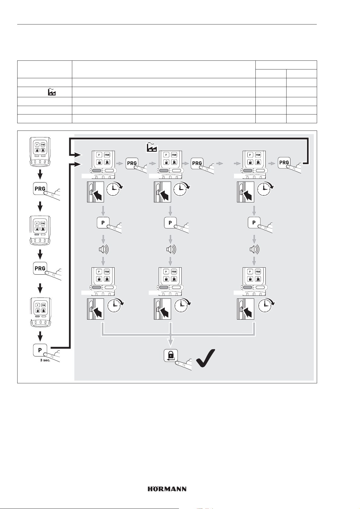
FRANÇAIS
7.2.3 Durée de maintien du pêne
Le paramètre de durée de maintien de pêne permet de régler le temps pendant lequel le pêne est rétracté pour ouvrir la
porte.
Paramètres Réglages LED
Gauche Droite
1 Env. 1seconde 1 × YE
2
3 Env. 5secondes 3 × YE
4 Env. 10secondes 4 × YE
5 Env. 20secondes 5 × YE
Env. 3secondes 2 × YE
GN
YE
3 sec.
2 x
1x YE 2x YE 5x YE
1 sec.
3 sec.
1x YE 2x YE 5x YE
1 sec.
1x
3 sec.
3 sec.
3 sec.
1 x
…
1 x
20 sec.
3 sec.
20 sec.
54
2 x
4555360 B0 / 42-2023 / DX
Page 55
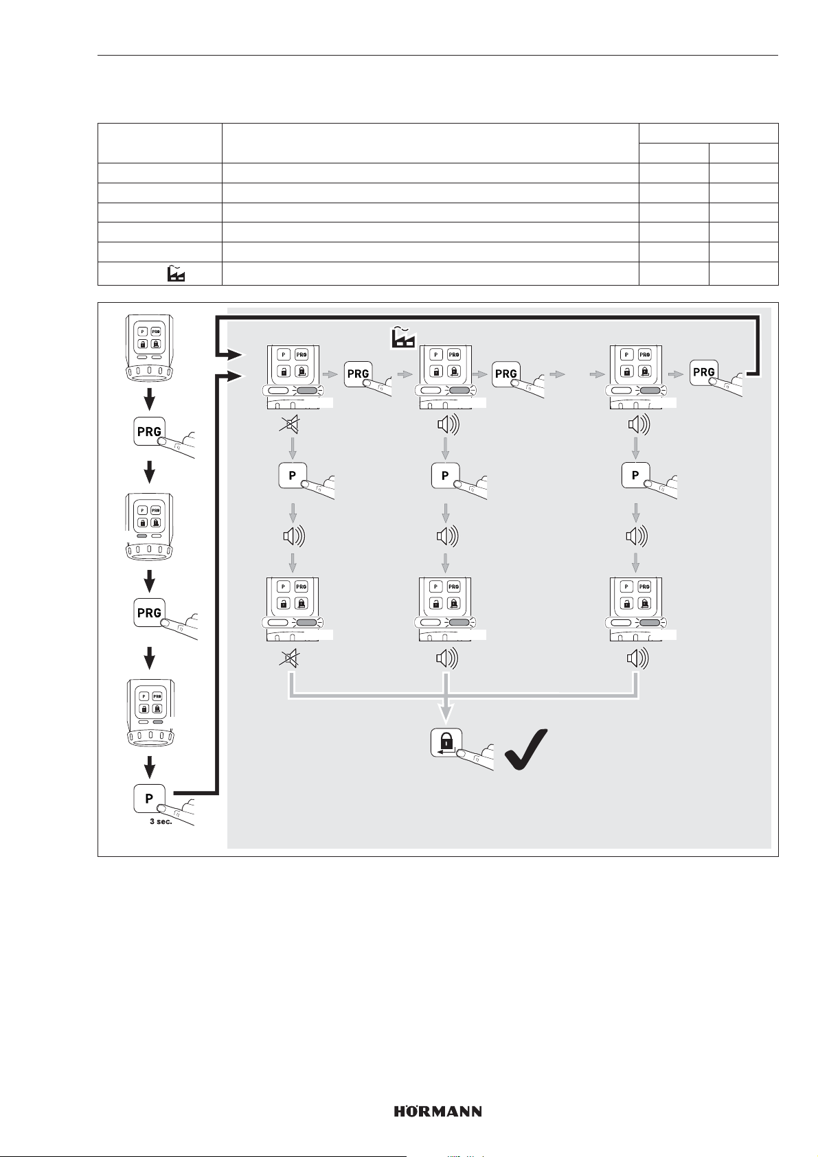
7.2.4 Signaleur
Ces paramètres permettent de régler les propriétés du signal.
Paramètres Réglages LED
Gauche Droite
1 Eteint 1 × GN
2 Uniquement les touches 2 × GN
3 Uniquement les positions finales 3 × GN
4 Seule la position finale est verrouillée 4 × GN
5 Touches et position finale verrouillées 5 × GN
6
Touches et positions finales 6 × GN
FRANÇAIS
GN
3 sec.
3 x
GN
1x GN 2x GN 6x GN
3 sec.
1x GN 2x GN 6x GN
1x
3 sec.
2 x
1 x
…
1 x
3 sec.
4555360 B0 / 42-2023 / DX
55
Page 56
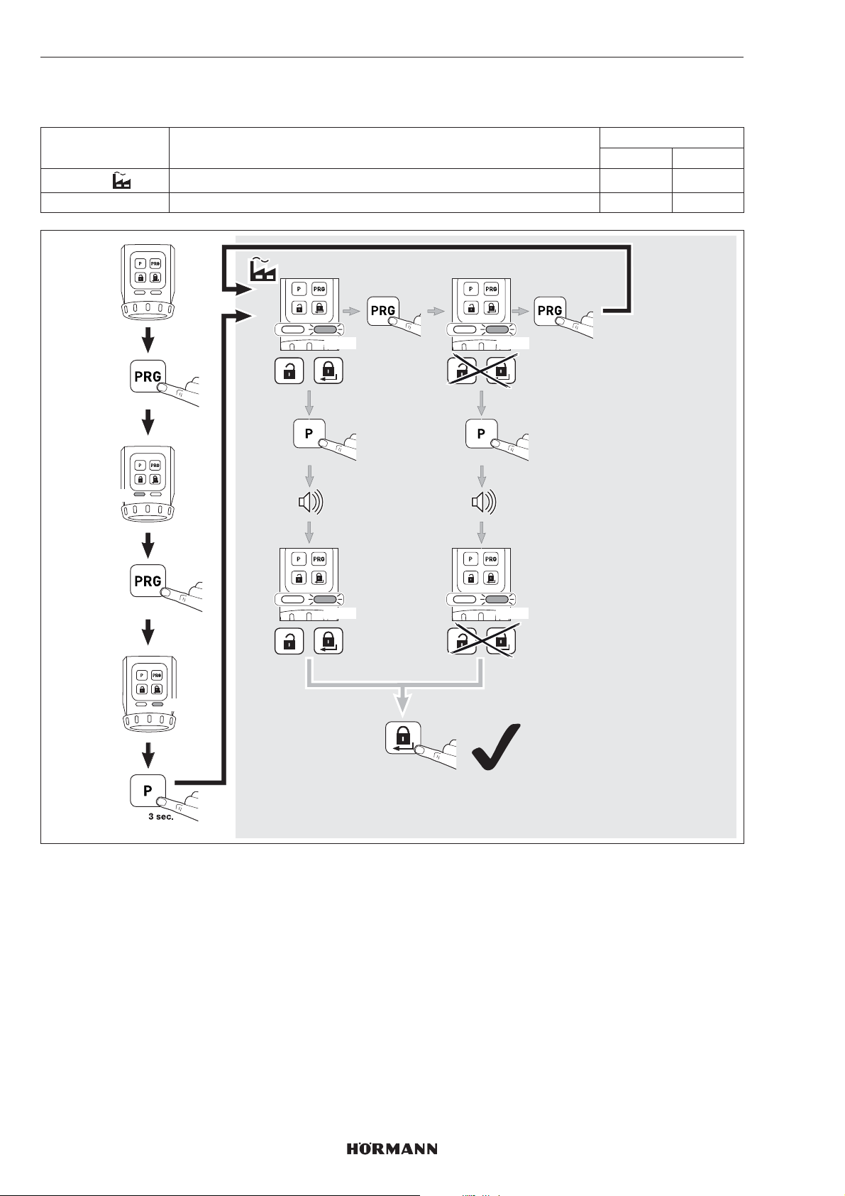
FRANÇAIS
7.2.5 Panneau à touches tactiles
Ces paramètres permettent de désactiver la commande de la touche de déverrouillage et de la touche deverrouillage.
Paramètres Réglages LED
Gauche Droite
1
2 Désactiver 2 × RD
Activer 1 × RD
GN
3 sec.
4 x
RD
1x RD 2x RD
3 sec.
1x RD 2x RD
1x
1 x
3 sec.
56
2 x
4555360 B0 / 42-2023 / DX
Page 57
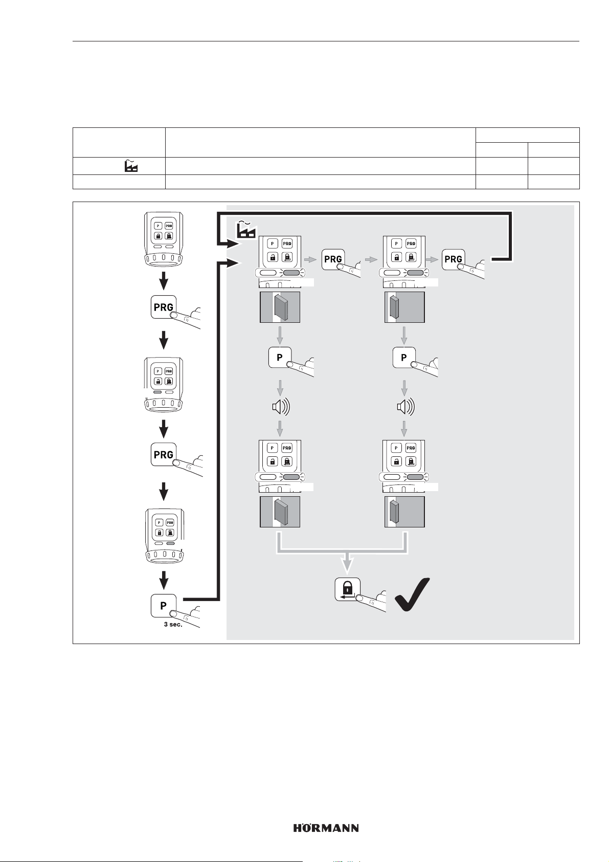
7.2.6 Réduction du verrouillage
Ces paramètres permettent de réduire un verrouillage à 2tours à un verrouillage à 1tour.
REMARQUE
Nous vous recommandons de conserver le réglage d’usine pour des raisons de sécurité.
Paramètres Réglages LED
Gauche Droite
1
2 Un seul verrouillage 2 × YE
Automatique 1×YE
FRANÇAIS
GN
3 sec.
5 x
YE
1x YE 2x YE
3 sec.
1x YE 2x YE
1x
1 x
1x
3 sec.
1x
4555360 B0 / 42-2023/ DX
2 x
57
Page 58
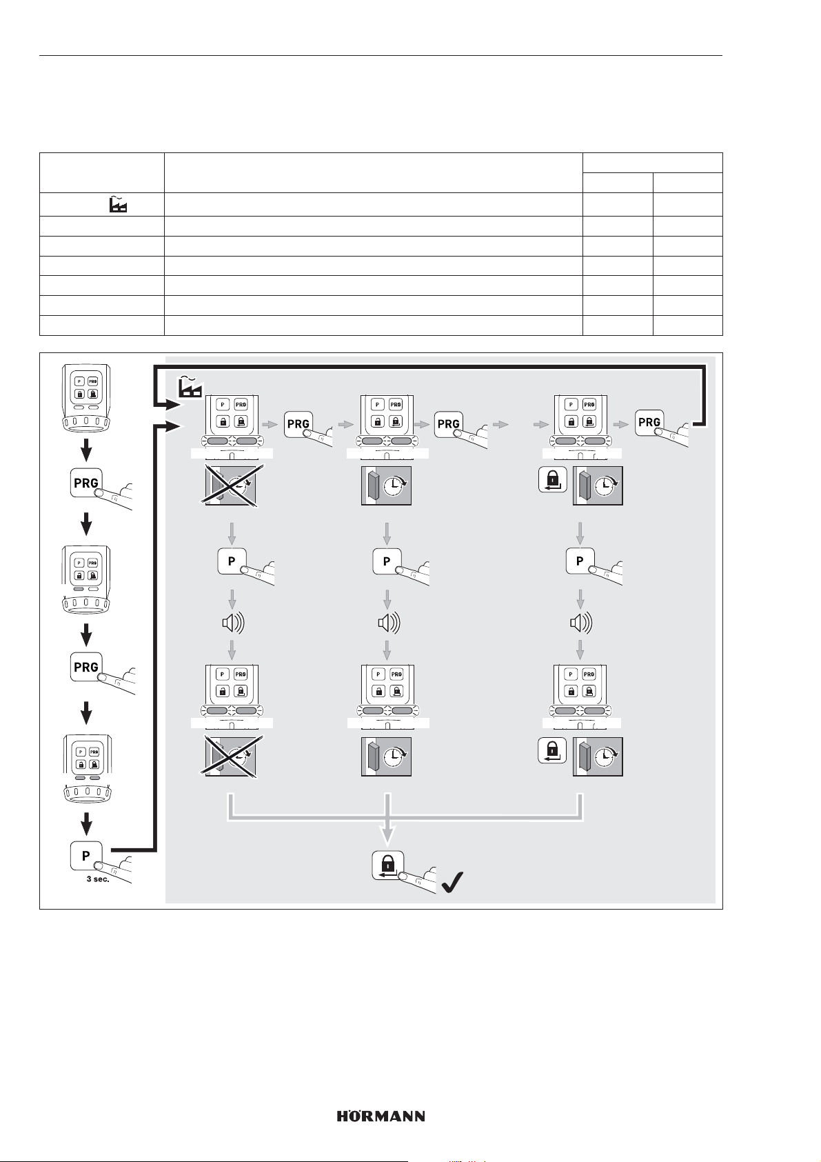
FRANÇAIS
7.2.7 Verrouillage de confort (verrouillage automatique)
Ces paramètres permettent de définir si la serrure se verrouille automatiquement après un temps défini ou après un appui
de touche et un temps défini. Veillez à ce que la porte soit fermée avant expiration du temps défini pour assurer un
verrouillage sûr de la porte.
Paramètres Réglages LED
Gauche Droite
1
2 Env. 30secondes après avoir atteint la position finale Déverrouillé 2×GN 2×GN
3 Env. 60secondes après avoir atteint la position finale Déverrouillé 3×GN 3×GN
4 Env. 120secondes après avoir atteint la position finale Déverrouillé 4×GN 4×GN
5 Env. 10secondes après avoir appuyé sur la touche de verrouillage 5× GN 5 ×GN
6 Env. 20secondes après avoir appuyé sur la touche de verrouillage 6× GN 6 ×GN
7 Env. 30secondes après avoir appuyé sur la touche de verrouillage 7× GN 7 ×GN
Inactif 1 × GN 1× GN
GN
GN
3 sec.
6 x
GN
1x GN 2x GN 7x GN
1x GN 2x GN 7x GN
1x GN 2x GN 7x GN
3 sec.
1x GN 2x GN 7x GN
1x
ca. 30 sec.
3 sec.
ca. 30 sec.
1 x
…
1 x
ca. 30 sec.
3 sec.
ca. 30 sec.
2 x
Désactivation à court terme du verrouillage de confort (paramètres 2, 3 et 4)
Vous pouvez désactiver le verrouillage de confort.
▶
Appuyez sur la touchePRG.
Le verrouillage de confort est désactivé.
Le verrouillage de confort est à nouveau activé avec la prochaine commande de verrouillage.
58
4555360 B0 / 42-2023/ DX
Page 59
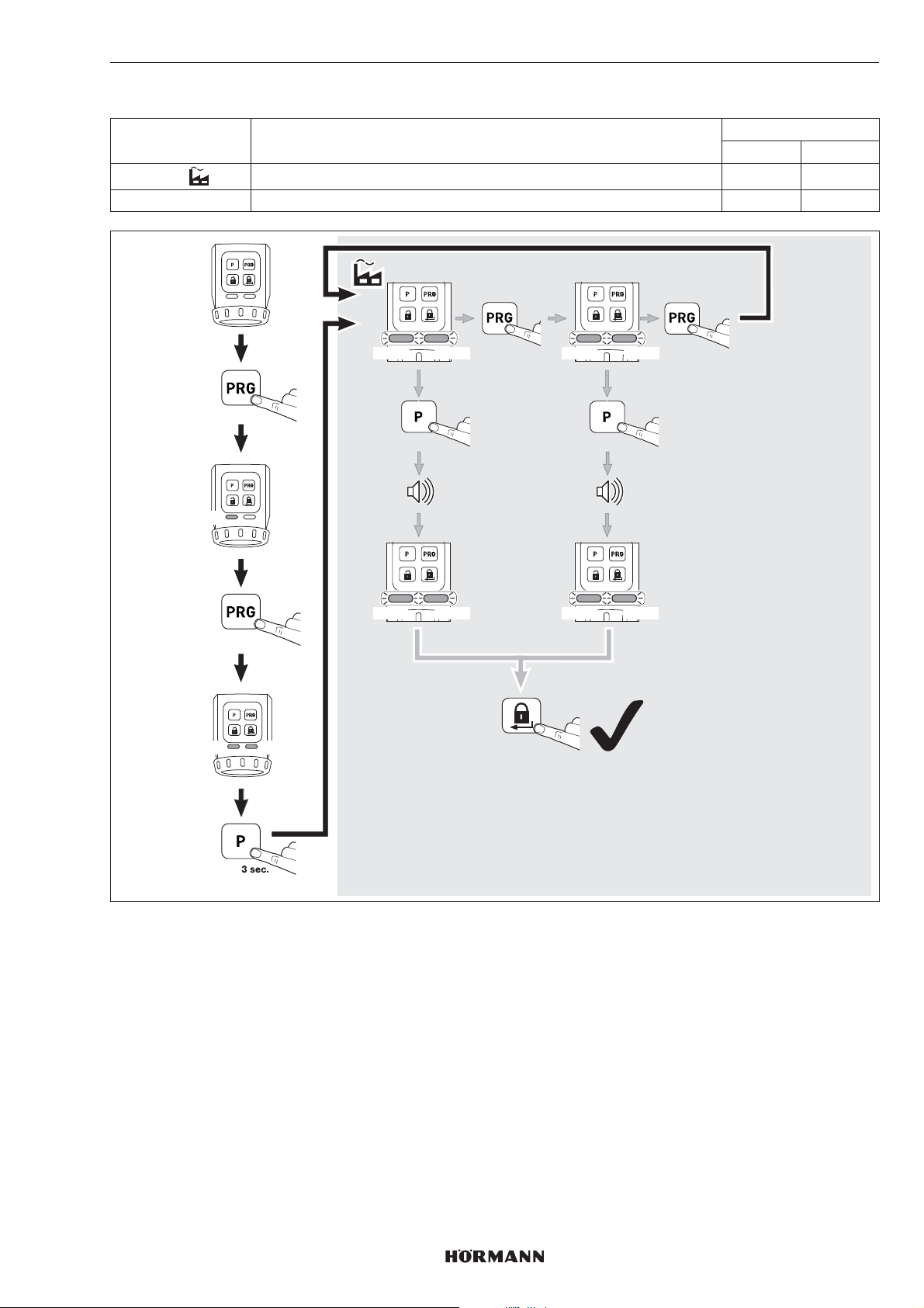
7.2.8 Réinitialisation de l’appareil
Paramètres Réglages LED
Gauche Droite
1
2 Trajets d’apprentissage et fonctions 2 × RD 2 ×RD
Uniquement les trajets d’apprentissage 1 × RD 1 ×RD
FRANÇAIS
GN
RD
3 sec.
7 x
RD
1x RD 2x RD
1x RD 2x RD
1x RD 2x RD
3 sec.
1x RD 2x RD
1x
2 x
1 x
3 sec.
4555360 B0 / 42-2023/ DX
59
Page 60
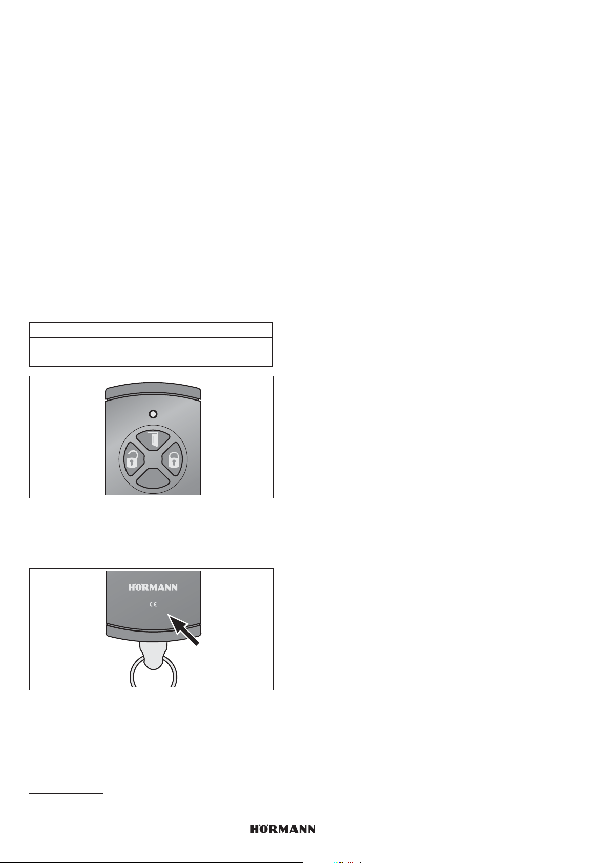
FRANÇAIS
8 Système radio
8.1 Module radio intégré
Jusqu’à 100codes radio d’émetteurs à 4touches HSE
4-SK-BS ou d’émetteurs de sécurité HSSE 4-SK peuvent
être transmis et répartis sur les différents canaux
disponibles. Si plus de 100codes radio sont transmis, les
codes radio appris en premier seront effacés.
Les codes radio d’autres émetteurs* ne peuvent pas être
appris sur la motorisation de serrure de porte. Parcontre,
l’émetteur à 4touches HSE 4-SK-BS etl’émetteur de
sécurité HSSE 4-SK peuvent transmettre leurs codes radio
à d’autres émetteurs BiSecur*.
8.2 Emetteur
La motorisation de serrure de porte est fournie avec un
émetteur à 4touches HSE4-SK dont les codes radio
doivent être appris sur la motorisation de serrure de porte.
▶
Voir chapitre8.3
Affectation des touches
Gauche Déverrouiller
En haut Ouvrir
Droite Verrouiller
REMARQUE
La transmission des codes radio de l’émetteur HSE4SK à
d’autres émetteurs* n’est pas possible siaucun indice
n’est indiqué ou si l’indice spécifié est-1 ou -2.
8.3 Apprentissage des codes radio
d’unémetteur HSE 4-SK
Lors de l’apprentissage des codes radio d’un émetteur
HSE4SK, les 3canaux sont appris simultanément.
1. Appuyez brièvement 1 × sur la touche P
delamotorisation de serrure de porte.
– La LED droite clignote lentement en bleu.
2. Tenez l’émetteur devant la motorisation de serrure de
porte.
3. Appuyez sur la touche Ouvrir de l’émetteur
etmaintenez-la enfoncée.
– La LED s’allume en bleu pendant 2secondes, puis
s’éteint.
– Après 5secondes, la LED clignote en alternance en
rouge et en bleu.
– L’émetteur envoie les codes radio.
4. Lorsque les codes radio sont reconnus, la LED dela
motorisation clignote rapidement en bleu.
– La LED s’éteint après 2secondes.
5. Relâchez la touche d’émetteur.
6. Appuyez sur la touche P pour terminer laprocédure
d’apprentissage.
Les codes radio de l’émetteur sont appris.
8.4 Apprentissage des codes radio
d’unémetteur de sécurité HSSE 4-SK
Lors de l’apprentissage des codes radio d’un émetteur de
sécurité HSSE 4-SK, les 3canaux sont appris
simultanément.
Après cela, aucun autre émetteur HSE4-SK ou HSSE4-SK
avec la spécification d’indice -3 ne peut être appris sur la
motorisation. Une transmission vers d’autres émetteurs*
peut uniquement se faire par un processus de copie à
partir de l’émetteur de sécurité.
REMARQUE
Pour votre propre sécurité, nous vous recommandons de
supprimer les codes radio appris au préalable sur la
motorisation de serrure de porte lorsque vous:
– procédez à l’apprentissage d’un émetteur
desécurité.
– avez effectué une réinitialisation de l’appareil sur
l’émetteur de sécurité.
▶
Voir chapitre8.3
HSE4-868-BS
* Par ex. émetteur, passerelle
60
0498-2
4555360 B0 / 42-2023 / DX
Page 61

FRANÇAIS
Les codes radio de l’émetteur de sécurité sontappris.
REMARQUE
Pour procéder à la transmission / l’envoi d’un code radio,
vous disposez de 25secondes. Si l’opération n’a pas été
effectuée avec succès dans cet intervalle, vous devez
répéter le processus.
8.5 Suppression de tous les codes radio
Il est impossible d’effacer des touches d’émission oudes
fonctions de manière individuelle.
▶
Appuyez sur la toucheP et maintenez-la enfoncée.
– La LED clignote lentement en bleu pendant
5secondes.
– La LED clignote rapidement en bleu pendant
2secondes.
– La LED s’éteint.
Tous les codes radio sont supprimés.
8.6 Mode veille
Lorsque le mode veille est activé:
– une commande radio sur la motorisation n’estpas
possible,
– la durée de vie des piles est rallongée.
8.6.1 Activation du mode veille
▶
Maintenez la touche de verrouillage sur le panneau
tactile enfoncée pendant 5secondes.
La motorisation se met en position finale Serrure
verrouillée, le mode veille est activé et la LED droite
clignote 5 × en bleu.
REMARQUE
Si la motorisation se trouve déjà en position finale
Verrouillé, le mode veille est activé immédiatement.
9 Fonctionnement
9.1 Commande par panneau tactile
La commande par panneau tactile se fait en utilisant les
touches Déverrouiller / Ouvrir et Verrouiller.
9.2 Commande par radio
REMARQUE
Si le code radio d’une touche d’émetteur a été transmis
depuis un autre émetteur, actionnez 2 × la touche
d’émetteur pour le premier fonctionnement.
9.3 Commande par molette / clé
La commande par molette / clé est uniquement destinée
aux situations d’urgence.
REMARQUE
Après un déverrouillage par molette ou clé, une course de
référence de la motorisation s’effectue automatiquement
lors de la commande suivante. LaLED gauche clignote en
rouge.
10 Conditions de défaut
10.1 Trajets d’apprentissage
Message Cause Remède
Signal sonore
(60s) et
clignotement en
jaune des deux
LED
Erreur lors du
trajet d’apprentissage
Appuyez surune
des touches
dupanneau tactile
8.6.2 Désactivation du mode veille
▶
Appuyez sur la touche de déverrouillage ou sur
latouche de verrouillage sur le panneau tactile.
Le mode veille est désactivé et la LED droite s’allume
en bleu pendant 2secondes.
REMARQUE
Le mode veille est également désactivé si la molette ou la
clé est actionnée.
10.2 Fonctionnement normal
Message Cause Remède
Signal sonore
pendant 3s, suivi
de clignotement
en jaune de la LED
gauche pendant
3s
Signal sonore
(60s) et
clignotement en
jaune de la LED
gauche
Signal sonore
(60s) et
clignotement en
rouge de la LED
gauche
Pile faible Remplacer toutes
les piles en même
temps
Erreur pendant
un trajet / trajet
de référence
Erreur pendant
un trajet de
référence
Appuyez sur une
des touches du
panneau tactile
Nouvelle
commande de
trajet par radio
(uniquement
Ouvrir ou
Déverrouiller)
Appuyez sur une
des touches du
panneau tactile
Nouvelle
commande de
trajet par radio
(uniquement
Ouvrir ou
Déverrouiller)
4555360 B0 / 42-2023 / DX
61
Page 62
FRANÇAIS
11 Nettoyage
ATTENTION
Endommagement de la motorisation de serrure de
porte dû à un nettoyage incorrect
Le nettoyage de la motorisation de serrure de porte à
l’aide de produits de nettoyage inappropriés peut altérer
le boîtier ainsi que les touches.
▶
Nettoyez la motorisation de serrure de porte
uniquement à l’aide d’un chiffon propre ethumide.
12 Elimination
Eliminez les emballages par type.
Les appareils électriques et électroniques doivent
être remis aux points de collecte prévus à cet effet.
14 Déclaration de conformité UE
Par la présente, la société Hörmann KG
Verkaufsgesellschaft déclare que le type d’installation sans
fil Motorisation de serrure de porte sans fil SmartKey
satisfait à la directive 2014/53/UE.
Le texte intégral de la déclaration de conformité UE est
disponible à l’adresse Internet suivante :
www.hoermann-docs.com/277127
Jetez les piles séparément. Chaque utilisateur a le
devoir légal de restituer les piles dans un centre de
collecte de sa commune, de son quartier ou du
commerce.
13 Données techniques
Motorisation de serrure de porte
Modèle SmartKey
Fréquence 868MHz
Puissance d’émission Max. 10mW(PIRE)
Alimentation électrique • 4piles de 1,5V, type AA
(LR6), alcaline au
manganèse
ou
• 4piles rechargeables de
1,2V, type AA (HR6), nickelhydrure métallique
Temp. ambiante admise 0°C à +40°C
Indice de protection IP20
62
4555360 B0 / 42-2023 / DX
Page 63

Índice
1 Acerca de estas instrucciones .......................64
1.1 Símbolos utilizados ...........................................64
2 Indicaciones de seguridad..............................64
2.1 Uso apropiado ...................................................64
2.2 Uso no apropiado ..............................................64
2.3 Indicaciones de seguridad para
elfuncionamiento ..............................................64
3 Volumen de suministro ...................................64
4 Descripción del producto ...............................65
5 Montaje .............................................................66
5.1 Comprobar las propiedades de la puerta ..........66
5.2 Comprobar la puerta y el bombín ......................66
5.3 Serrar la cabeza de la llave................................66
5.4 Montar la chapa de soporte ..............................67
6 Puesta en marcha ............................................69
6.1 Colocar las pilas ................................................69
6.2 Trabajos finales ..................................................69
6.3 Programación del automatismo ........................70
7 Funciones .........................................................71
7.1 1er.Nivel de menú / funciones ...........................71
7.2 2.º Nivel de menú / parámetros ..........................71
8 Radiofrecuencia ...............................................80
8.1 Módulo por radiofrecuencia integrado ..............80
8.2 Emisor manual ...................................................80
8.3 Programación del código deradiofrecuencia
de un emisor manual HSE4-SK ........................80
8.4 Programación de los códigos der
adiofrecuencia de un emisor manual
deseguridad HSSE4SK ..................................80
8.5 Borrar todos los códigos deradiofrecuencia ....81
8.6 Modo reposo .....................................................81
9 Funcionamiento ...............................................81
9.1 Manejo por campo de sensores ........................81
9.2 Manejo por radiofrecuencia ...............................81
9.3 Manejo por rueda manual/llave .........................81
10 Estados de error ..............................................81
10.1 Recorridos de aprendizaje .................................81
10.2 Funcionamiento normal .....................................81
11 Limpieza ...........................................................82
12 Reciclaje ...........................................................82
13 Datos técnicos .................................................82
14 Declaración UE de conformidad ....................82
ESPAÑOL
Quedan prohibidas la divulgación ylareproducción de este documento,
asícomo su uso indebido y la comunicación del contenido, salvo
porautorización explícita. En caso deinfracción se hace responsable
deindemnización por daños y perjuicios. Se reservan todos los derechos,
enparticular para el caso de concesión de patente, de modelo de utilidad
oindustrial. Reservado el derecho amodificaciones.
4555360 B0 / 42-2023 / DX
63
Page 64
ESPAÑOL
1 Acerca de estas instrucciones
Las instrucciones contienen información importante sobre
el producto, en particular indicaciones de seguridad y
advertencia.
▶
Lea todas las instrucciones detenidamente.
▶
Guarde estas instrucciones cuidadosamente.
AVISO
Observe todas las regulaciones, normas y disposiciones
de seguridad relevantes del lugar de uso del SmartKey.
1.1 Símbolos utilizados
Aviso importante
Disposición o actividad permitida
Disposición o actividad nopermitida
2.2 Uso no apropiado
El automatismo de cerradura de puerta no debe utilizarse
en:
– en puertas cortafuego sin comprobación
– puertas de emergencia
2.3 Indicaciones de seguridad para
elfuncionamiento
ADVERTENCIA
En caso de emergencia, una puerta cerrada conllave
en un edificio de viviendas puede serpeligrosa.
Al querer salir de un edificio en una situación de pánico,
una puerta cerrada con llave puede resultar una trampa
mortal.
▶
No utilice el automatismo de cerradura en la puerta
de entrada principal de un edificio de viviendas.
ATENCIÓN
Fallos del funcionamiento por influencias delmedio
ambiente
Si no se tiene en cuenta, puede perjudicarse
elfuncionamiento.
Temperatura ambiente permitida: de0°Chasta+40°C.
Ajuste de fábrica
2 Indicaciones de seguridad
2.1 Uso apropiado
El automatismo de cerradura de puerta es una unidad
– para bloqueo y desbloqueo accionado por motor;
– para puertas con bloqueos de 2giros como
máximo (2vueltas de llave);
– para espacios interiores frescos;
– para puertas cortafuego de chapa de acero
T30/ EI
redondas de la serie H3OD, STS30 / STU30, D65,
STS / STU.
Para puertas de acero con guías de placa corta utilice una
placa adaptadora de acero inoxidable.
En el automatismo, la llave está introducida en
unalojamiento con el que se puede bloquear, desbloquear
y abrir el bombín. El impulso para elautomatismo procede
de, por ejemplo:
– el campo de sensores con teclas,
– un emisor manual,
– un lector dactilar vía radiofrecuencia,
– la aplicación Hörmann Homee.
No están permitidos otros usos. El fabricante no asume
responsabilidad alguna por daños resultantes de un uso no
apropiado o un manejo incorrecto.
30 de Hörmann con guías de rosetas
2
▶
Después de la programación o la ampliación del
sistema de radiofrecuencia realice una prueba
defuncionamiento.
▶
Utilice exclusivamente piezas originales para lapuesta
en marcha o la ampliación del sistema de
radiofrecuencia.
• Las condiciones locales pueden influir sobre elalcance
del sistema de radiofrecuencia.
3 Volumen de suministro
• Automatismo de cerradura de puerta SmartKey
• Chapa de soporte
• Emisor manual HSE4-SK-BS
• 4 pilas de 1,5V, tipo:AA (LR6), alcalinademanganeso
• Material de fijación
• Instrucciones breves
64
4555360 B0 / 42-2023 / DX
Page 65
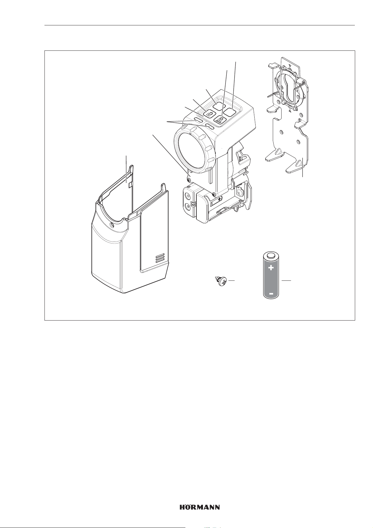
4 Descripción del producto
2
1
ESPAÑOL
8
7
6
5
4
P
PRG
3
9
1 Cubierta
2 Automatismo
3 LED (izquierda/derecha), multicolor
4 Campo de sensores con teclas
5 Tecla de desbloqueo
6 Pulsador P
7 Tecla de bloqueo
8 Tecla PRG
9 Chapa de soporte
10 Batería de 1,5V, tipoAA (LR6), alcalinademanganeso (4 uds.)
11 Tornillo, 4,2 × 9,5mm (4 uds.)
11
10
AA
4555360 B0 / 42-2023 / DX
65
Page 66
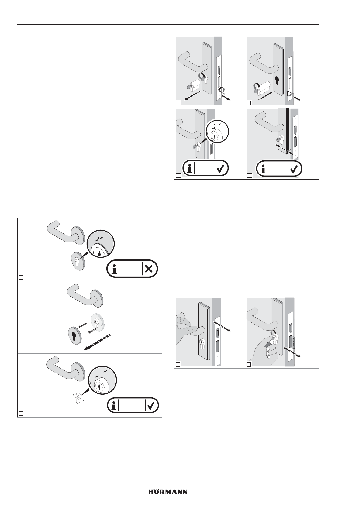
ESPAÑOL
5 Montaje
El automatismo de cerradura de puerta requiere una llave
introducida permanentemente en el bombín. Elcilindro:
– debe ser un bombín Euro según DIN18252
yDINEN1303;
– debe tener la función de emergencia y peligro, es
decir, el cilindro se puede abrir desde fuera con otra
llave aunque en el interior haya una llave
introducida.
5.1 Comprobar las propiedades de la puerta
Es necesario que el cilindro sobresalga entre 7– 12mm en
el lado interior de la puerta.
▶
Sustituya el cilindro si:
– el cilindro no cuenta con la función deemergencia y
peligro
– el saliente del cilindro es inferior a 7mm
2.
3.
4
1.
X
1.
2.
5
3.
Y
CONSEJO
Recomendamos el montaje del automatismo a ser posible
directamente sobre la hoja de puerta.
La dimensión desde el centro del ojo de la cerradura hasta
el borde exterior de la puerta o el cerco debe ser de al
menos 35mm; de lo contrario, la puerta no se podrá abrir
después del montaje.
X
X < 7 mm
1
X = 7-12
6
mm
7
Y ≥ 35
mm
5.2 Comprobar la puerta y el bombín
La puerta y el bombín deben encontrarse en perfecto
estado mecánico y funcionar con suavidad.
▶
Antes de montar el automatismo de cerradura
depuerta, compruebe el ajuste de su puerta
ydelcilindro.
▶
Compruebe si su cerradura tiene 1 o 2 giros parael
bloqueo.
▶
Compruebe si, con la puerta abierta y cerrada,
esposible realizar los mismos bloqueos (1 giro
o2giros). Si con la puerta cerrada con un bloqueo de
2 giros solo es posible el bloqueo con1 giro, entonces
se deben programar los recorridos y las fuerzas del
automatismo con lapuerta cerrada.
check!
66
2
1
X
2
check!
5.3 Serrar la cabeza de la llave
1. Desbloquee la puerta.
X = 7-12 mm
3
2. Mida 4 – 7mm entre el bombín y la cabeza delallave.
3. Sierre la cabeza de la llave.
4. Quite las rebabas del corte hecho con la sierra.
5. Introduzca de nuevo la llave en el cilindro.
4555360 B0 / 42-2023/ DX
Page 67
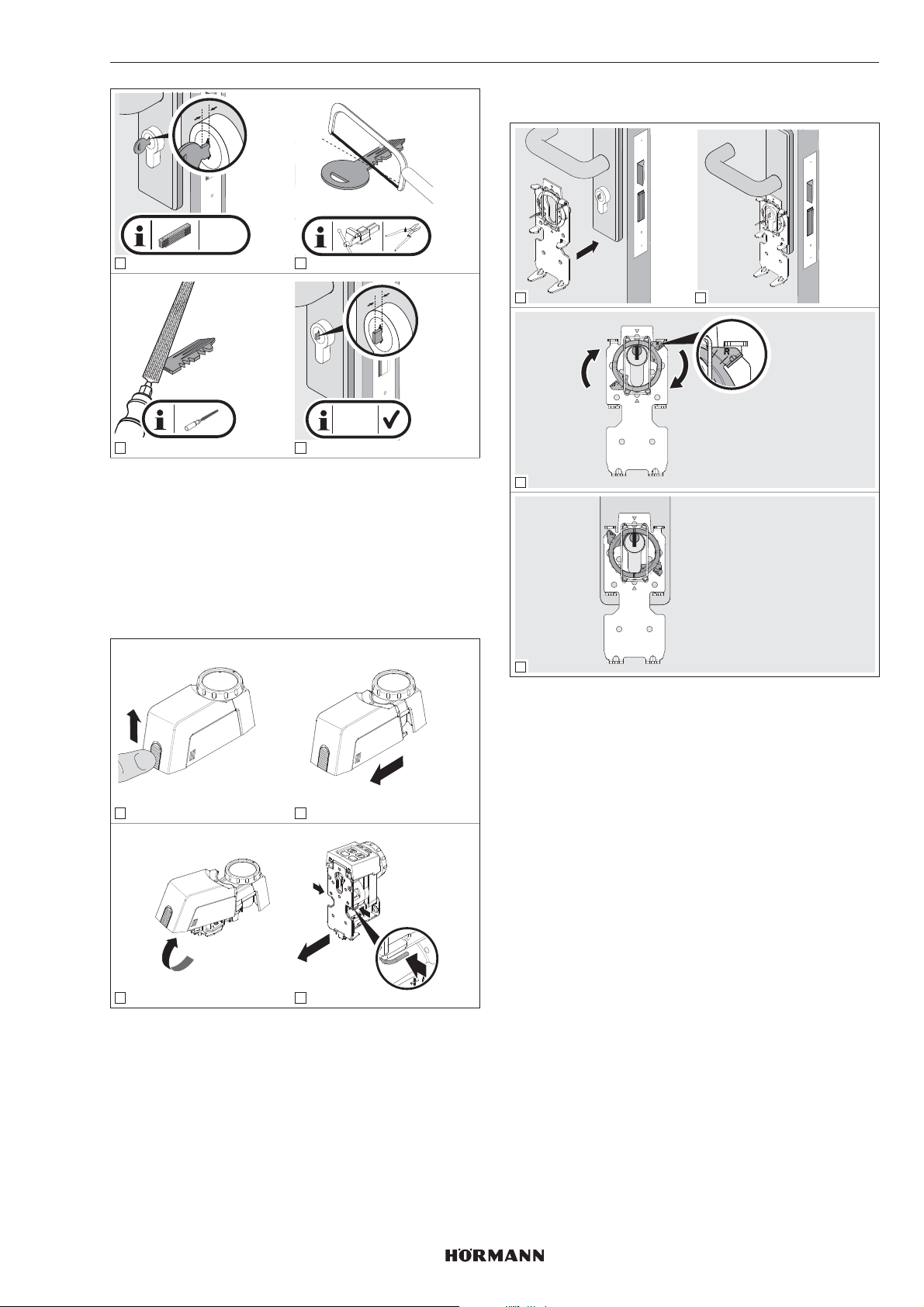
ESPAÑOL
y
y = 4-7
mm
1 2
y
y = 4-7
mm
3
4
5.4 Montar la chapa de soporte
1. Desbloquee el bloqueo y mantenga la posición
dedesbloqueo.
2. Retire la cubierta del automatismo.
3. Desbloquee la chapa de soporte.
4. Quite la chapa de soporte de la parte trasera
delautomatismo.
5.4.1 Inmovilizar la chapa de soporte
1 2
3
1 2
PRG
P
1.
press!
2.
3
4
Para montar la chapa de soporte, dispone de cuatro
posibilidades distintas que se pueden combinar:
a. Inmovilizar la chapa de soporte
▶
ver capítulo5.4.1
b. Pegar la chapa de soporte
▶
Ver capítulo 5.4.2
c. Atornillar la chapa de soporte
▶
Ver capítulo5.4.3
d. Chapa de soporte con atornillamiento deroseta
▶
Ver capítulo5.4.4
4
▶
Gire el anillo de sujeción hacia la derecha hasta
eltope.
▶
A continuación compruebe el bombín. El cilindro debe
encontrarse en perfecto estado mecánico y funcionar
con suavidad.
4555360 B0 / 42-2023/ DX
67
Page 68
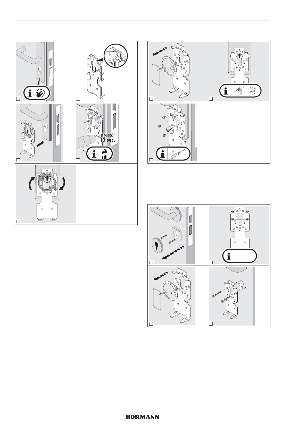
ESPAÑOL
5.4.2 Pegar la chapa de soporte
1 2
3 4
5.4.3 Atornillar la chapa de soporte
1 2
3
▶
Para puertas cortafuego utilice tornillos para chapa
cortos.
PH2
5
Limpieza de las superficies
▶
Utilice paños limpios y sin perfume que nodesprendan
pelusas.
▶
Utilice productos de limpieza adecuados ynoutilice
limpiadores domésticos grasos.
▶
Repita la limpieza hasta que la superficie esté limpia y
libre de grasa.
INDICACIÓN
Utilice siempre productos de limpieza y de conservación
adecuados. La conservación de unasuperficie intacta es
su responsabilidad.
5.4.4 Chapa de soporte con atornillamiento
deroseta
y
38 mm
y = 38 mm
1
3 4
▶
Preste atención a no perforar la cerradura empotrable.
Acorte los tornillos si fuera necesario.
2
68
4555360 B0 / 42-2023/ DX
Page 69
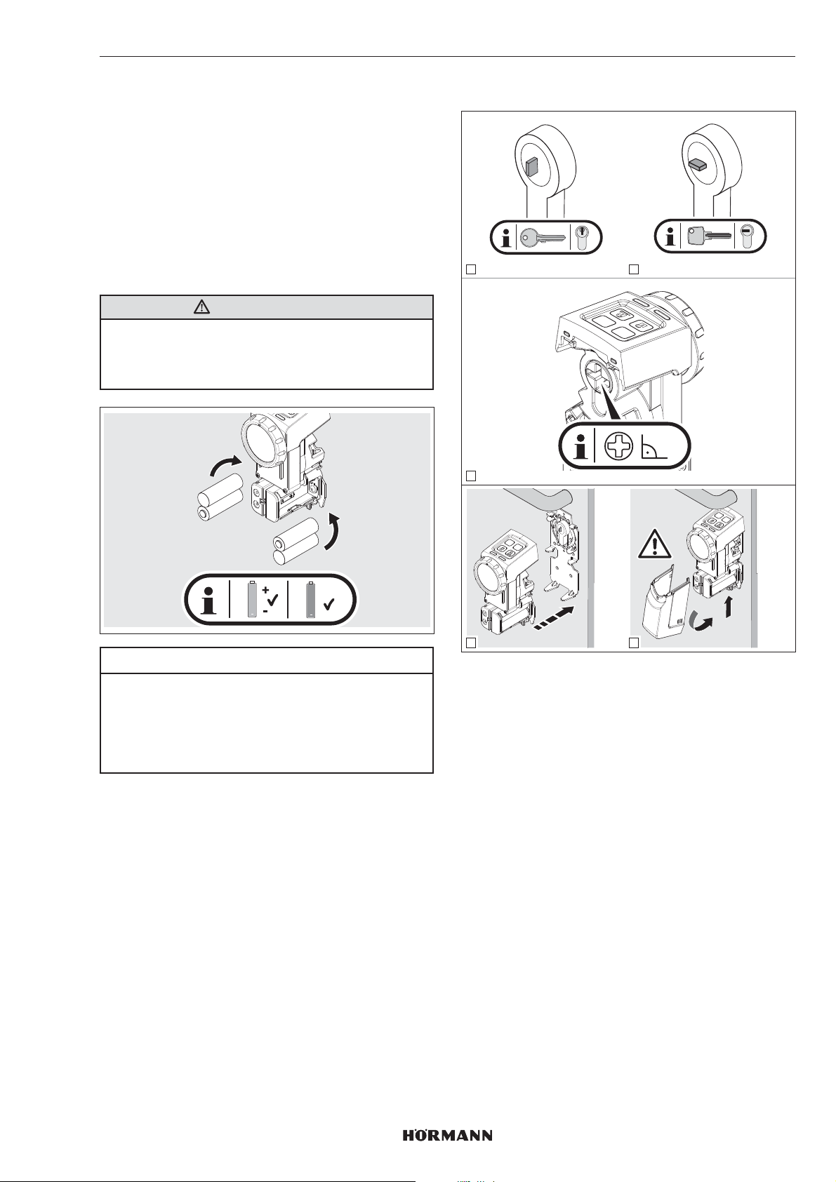
ESPAÑOL
6 Puesta en marcha
Una vez colocadas las pilas y cuando se apague elLED
azul, el automatismo de cerradura de puerta está listo para
el funcionamiento.
6.1 Colocar las pilas
Para el funcionamiento del automatismo de cerradura de
puerta utilice:
• 4 pilas de 1,5V, tipoAA (LR06), alcalina de manganeso
o bien
• 4 acumuladores de 1,2V, tipo: AA (HR6), níquel-metal
hidruro
ADVERTENCIA
Riesgo de explosión portipo de batería incorrecto
Existe riesgo de explosión cuando se instalan pilas del
tipo equivocado.
▶
Solo utilice pilas del tipo recomendado.
6.2 Trabajos finales
1 2
PRG
3
P
90°
+
AA
+
ACCU
ACCU
ATENCIÓN
Destrucción del automatismo de cerradura depuerta
por pilas derramadas
Las pilas pueden derramarse y destruir elautomatismo
de cerradura.
▶
Retire las pilas del automatismo de cerradura si no lo
va a utilizar durante un tiempo prolongado.
P
PRG
P
PRG
2.
click!
4
5
1.
1. Preste atención a la posición adecuada para lallave
dentada y la llave reversible.
2. Alinee en ángulo recto la ranura en cruz de la parte
posterior del automatismo con la rueda demano.
3. Introduzca el automatismo en la placa desujeción.
– El automatismo se encastra de forma audible.
4. Cierre el automatismo con la cubierta.
– La cubierta se encastra de forma audible.
4555360 B0 / 42-2023/ DX
69
Page 70
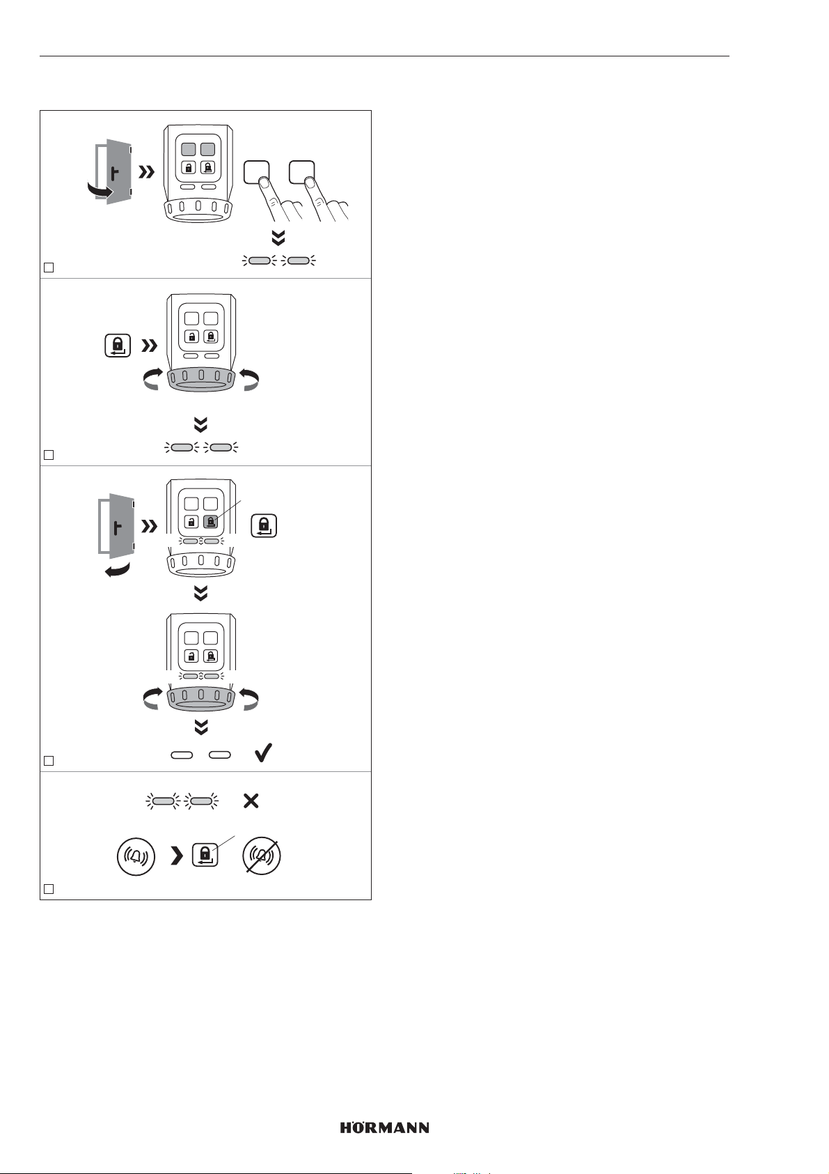
ESPAÑOL
6.3 Programación del automatismo
PRGP
1
PRGP
ca. 3 sec. - 10 sec.
2
YE YE
press 3 sec.
PRGP
+
YE YE
1. Pulse al mismo tiempo la tecla P y la tecla PRG
ymantenga las teclas pulsadas hasta que parpadeen
los dos LED amarillos.
2. Pulse la tecla de bloqueo.
El automatismo memoriza los recorridos del resbalón y
del pestillo. Después de alcanzar las posiciones
finales, termina el proceso.
3. Cierre la puerta.
4. Pulse la tecla de bloqueo.
El automatismo memoriza las fuerzas requeridas.
5. El automatismo ha sido programado.
Los LED se apagan.
INDICACIÓN
Si los LED parpadean rápidamente y suena una señal
acústica, se deberá subsanar la causa del error.
▶
Ver capítulo 10
6. Compruebe las funciones del automatismo mediante
las teclas del campo de sensores.
Timeout
Si no se pulsa ninguna tecla en el intervalo de
60segundos, el automatismo de cerradura de puerta
cambia automáticamente al modo de servicio.
El automatismo no ha sido memorizado.
press
PRGP
YE YE
PRGP
YE YE
3
YE YE
press
=
4
Para programar el automatismo se deben cumplir
lassiguientes condiciones:
• El automatismo no ha sido memorizado.
• El automatismo está montado en la puerta.
• La cerradura debe estar desbloqueada, es decir, todos
los pestillos deben estar completamente retraídos.
• La puerta está abierta.
70
4555360 B0 / 42-2023 / DX
Page 71
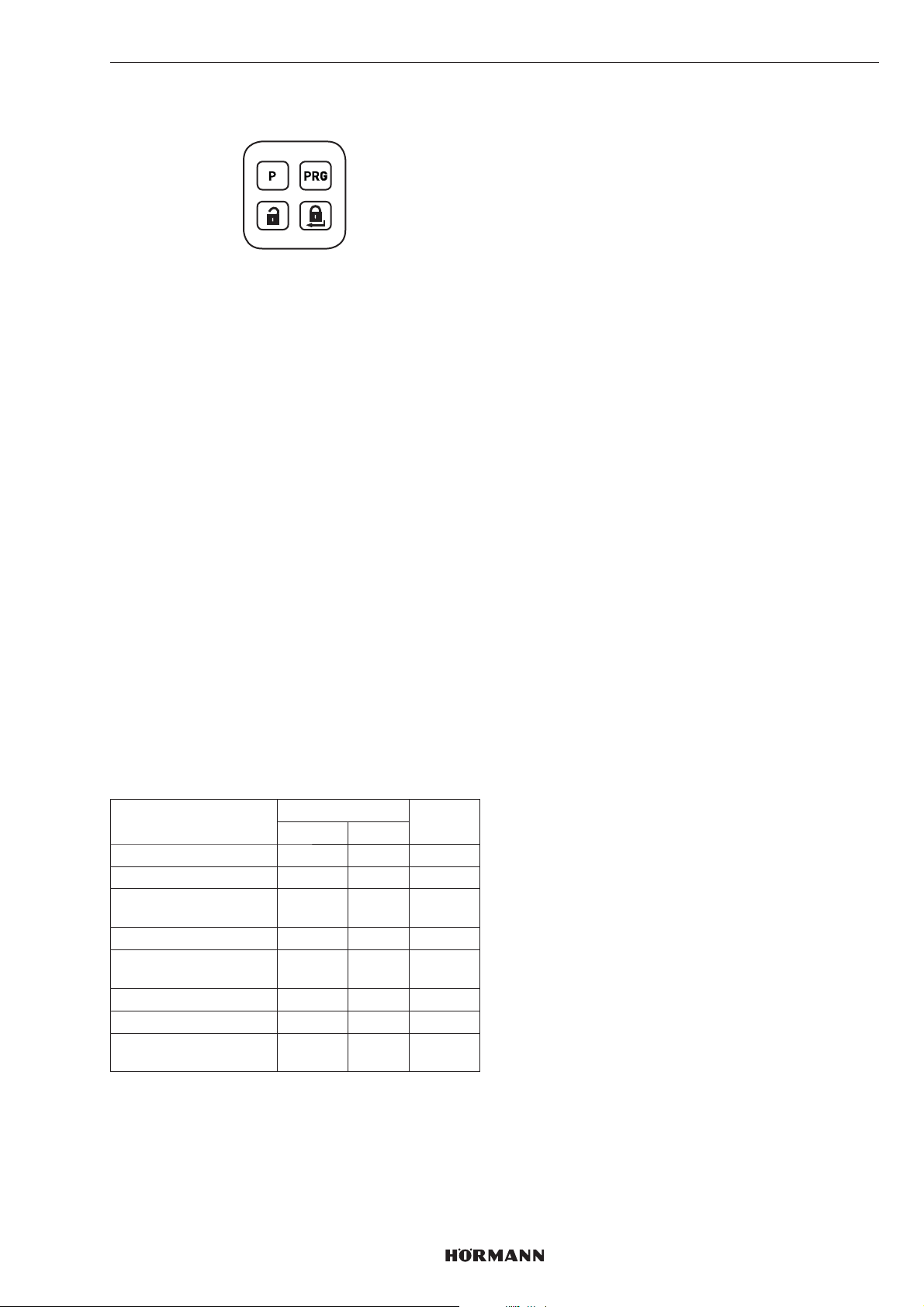
ESPAÑOL
7 Funciones
Las funciones del automatismo de cerradura de puerta se
pueden ajustar mediante la tecla P y la tecla PRG del
campo de sensores. Cada función dispone de diferentes
parámetros que permiten ajustes adicionales. Antes de la
puesta en marcha, todos los parámetros están en la
posición de ajuste de fábrica.
Solo se autoriza la modificación de las funciones cuando el
automatismo está en reposo.
INDICACIÓN
Tenga en cuenta que una modificación del ajuste
defábrica puede conducir a una menor vida útil de
labatería, por ejemplo al aumentar el par de apriete ola
velocidad.
Ajuste las funciones y los parámetros correspondientes de
acuerdo con las circunstancias locales y las adaptaciones
individuales.
7.1 1er.Nivel de menú / funciones
En el 1er nivel de menú se han asignado las funciones del
automatismo de cerradura de puerta.
1. Pulse la teclaPRG y manténgala presionada durante
3segundos.
El automatismo de cerradura de puerta cambia del
funcionamiento normal al 1er. nivel de menú.
2. Seleccione una función pulsando brevemente varias
veces la tecla PRG.
Los LED se iluminan en el color que corresponda a la
función seleccionada.
7.2 2.º Nivel de menú / parámetros
En el 2.º nivel de menú se han asignado los parámetros de
las funciones del 1er. nivel de menú. Sidesea ajustar un
parámetro, entonces cambie al2.ºnivel de menú.
1. Pulse la teclaP y manténgala presionada durante
3segundos.
El automatismo de cerradura de puerta cambia del 1er.
nivel de menú al 2.º nivel de menú. ElLEDparpadea
en el color que corresponda alparámetro ajustado.
2. Seleccione un parámetro pulsando brevemente varias
veces la tecla PRG.
Los LED parpadean en el color que corresponda ala
función seleccionada.
3. Active el parámetro seleccionado pulsando latecla P
durante 3segundos.
Si se ha activado el parámetro, se apagan los
LEDbrevemente y suena una señal acústica.
Acontinuación, los LED muestran el parámetro actual.
4. Pulse brevemente la tecla de bloqueo.
Pulsar 1 vez = 1er.nivel de menú
Pulsar 2 veces = modo de servicio
Para cancelar el ajuste de los parámetros:
▶
Pulse 2veces la tecla de bloqueo o espere a que pase
el tiempo Timeout.
Timeout
Si no se pulsa ninguna tecla en el intervalo de
60segundos, el automatismo de cerradura de puerta
cambia automáticamente al modo de servicio.
Funciones LED Capítulo
izquierdo derecho
Par de apriete GN 7.2.1
Velocidad RD 7.2.2
Tiempo de retención del
resbalón
Transmisor de señales GN 7.2.4
Campo de sensores con
teclas
Reducción del bloqueo YE 7.2.6
Bloqueo de confort GN GN 7.2.7
Restablecimiento de los
ajustes del aparato
GN = verde, RD = rojo, YE = amarillo
4555360 B0 / 42-2023 / DX
YE 7.2.3
RD 7.2.5
RD RD 7.2.8
71
Page 72
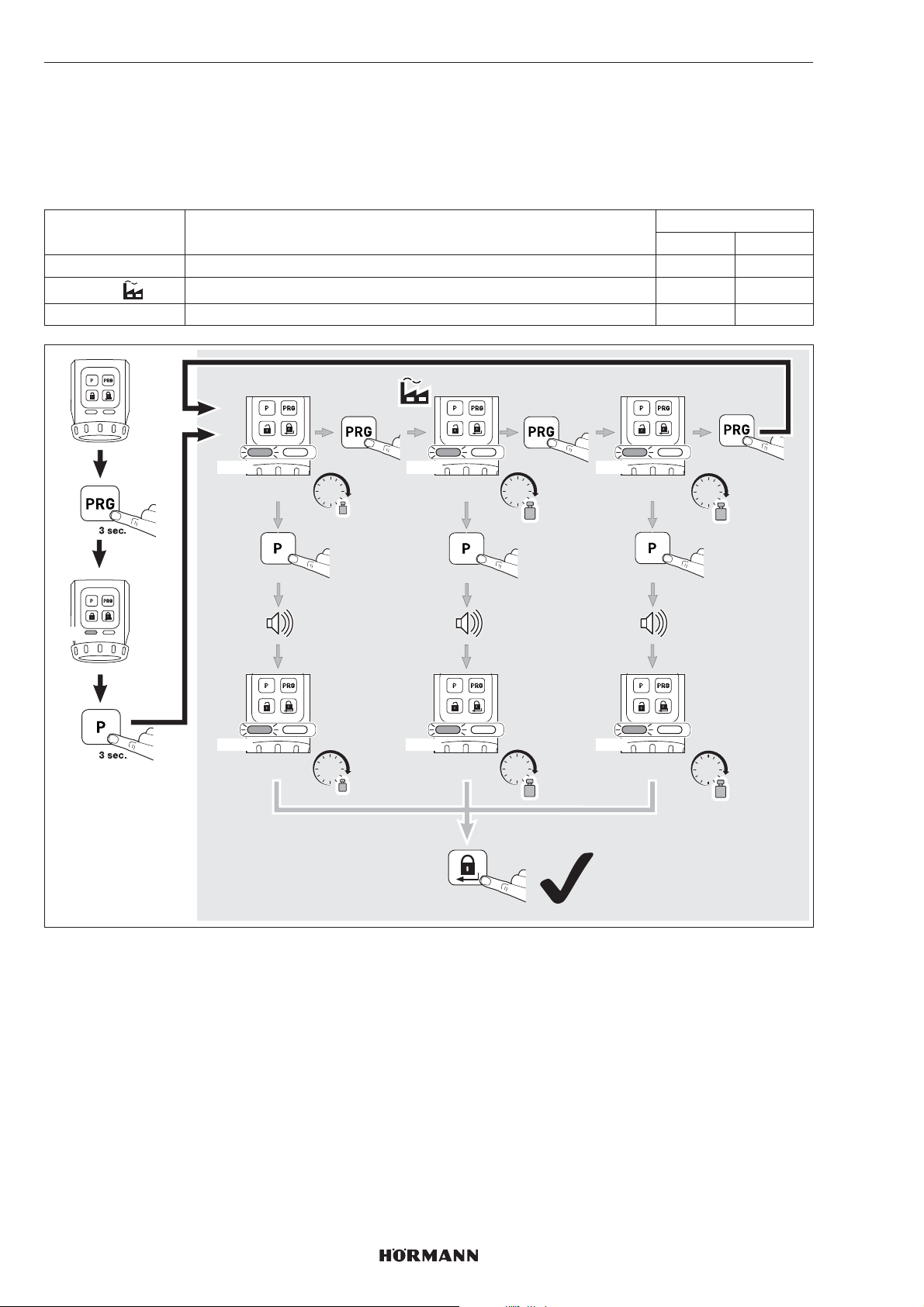
ESPAÑOL
7.2.1 Par de apriete
En función del estado de la puerta o del estado de cierre, el par de apriete de la tracción del resbalón se puede ajustar
mediante los parámetros 1 – 3.
INDICACIÓN
Tenga en cuenta que al aumentar el par de apriete se produce un aumento de la carga de la llave.
Parámetro Ajustes LED
izquierdo derecha
1 aprox. 1,0Nm 1 × GN
2
3 aprox. 1,5Nm 3 × GN
aprox. 1,2Nm 2 × GN
GN
1x GN 2x GN 3x GN
ca. 1,0 Nm ca. 1,2 Nm
1x GN 2x GN 3x GN
ca. 1,0 Nm
Nm
3 sec.
Nm
1x
3 sec.
ca. 1,2 Nm
2 x
Nm
Nm
1 x
ca. 1,5 Nm
ca. 1,5 Nm
1 x
Nm
3 sec.
Nm
72
4555360 B0 / 42-2023 / DX
Page 73
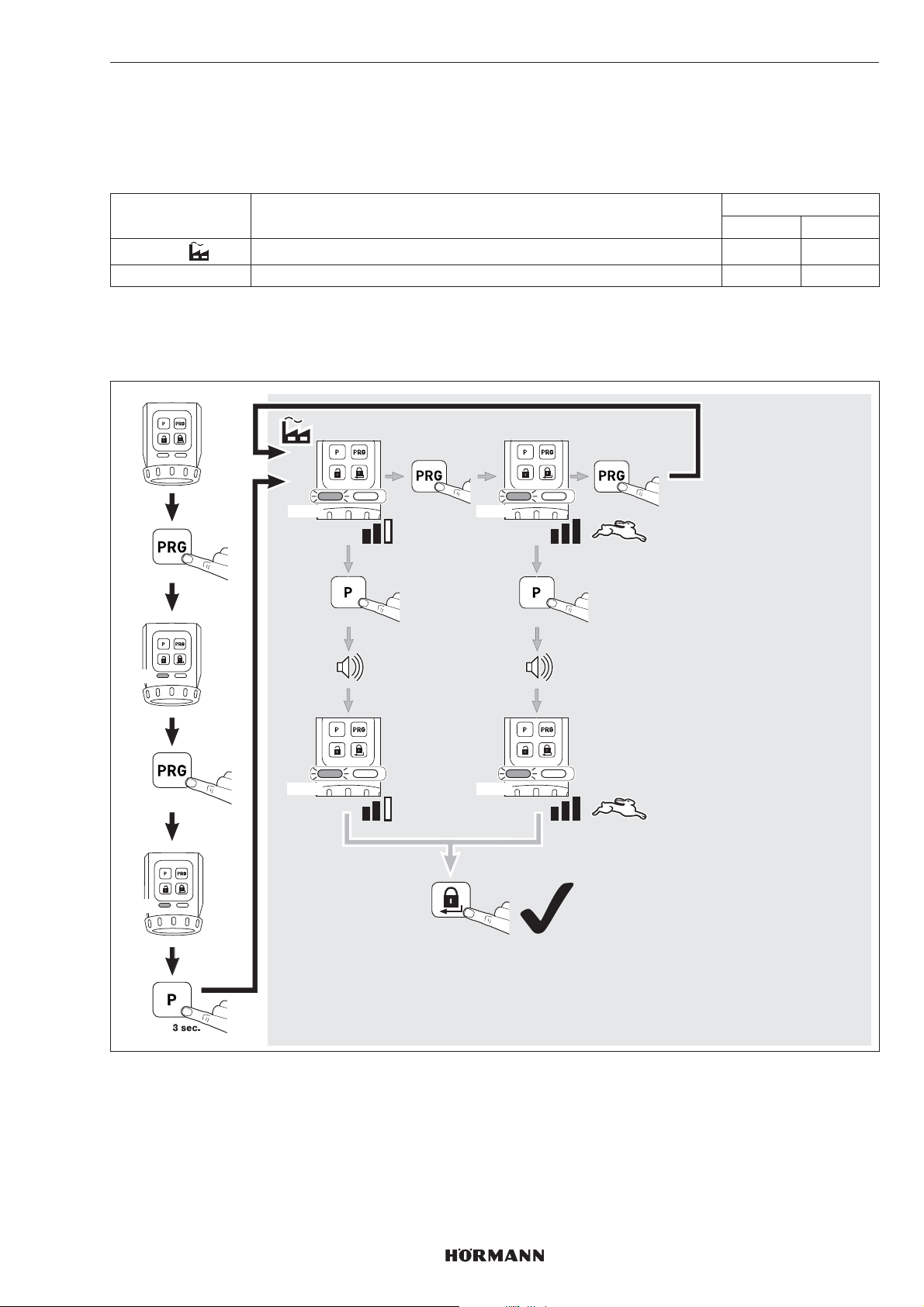
7.2.2 Velocidad
La velocidad al bloquear, desbloquear y abrir se puede ajustar mediante 2parámetros.
INDICACIÓN
Tenga en cuenta que al aumentar la velocidad se produce un aumento de la carga de la llave.
Parámetro Ajustes LED
izquierdo derecho
1
2 Máximo 2 × RD
CONSEJO
Recomendamos conservar los ajustes automáticos, ya que estos se adaptan automáticamente a las diferentes
circunstancias de la puerta.
Automático 1 × RD
ESPAÑOL
GN
RD
3 sec.
1 x
1x RD 2x RD
3 sec.
1x RD 2x RD
1x
2 x
1 x
3 sec.
4555360 B0 / 42-2023 / DX
73
Page 74
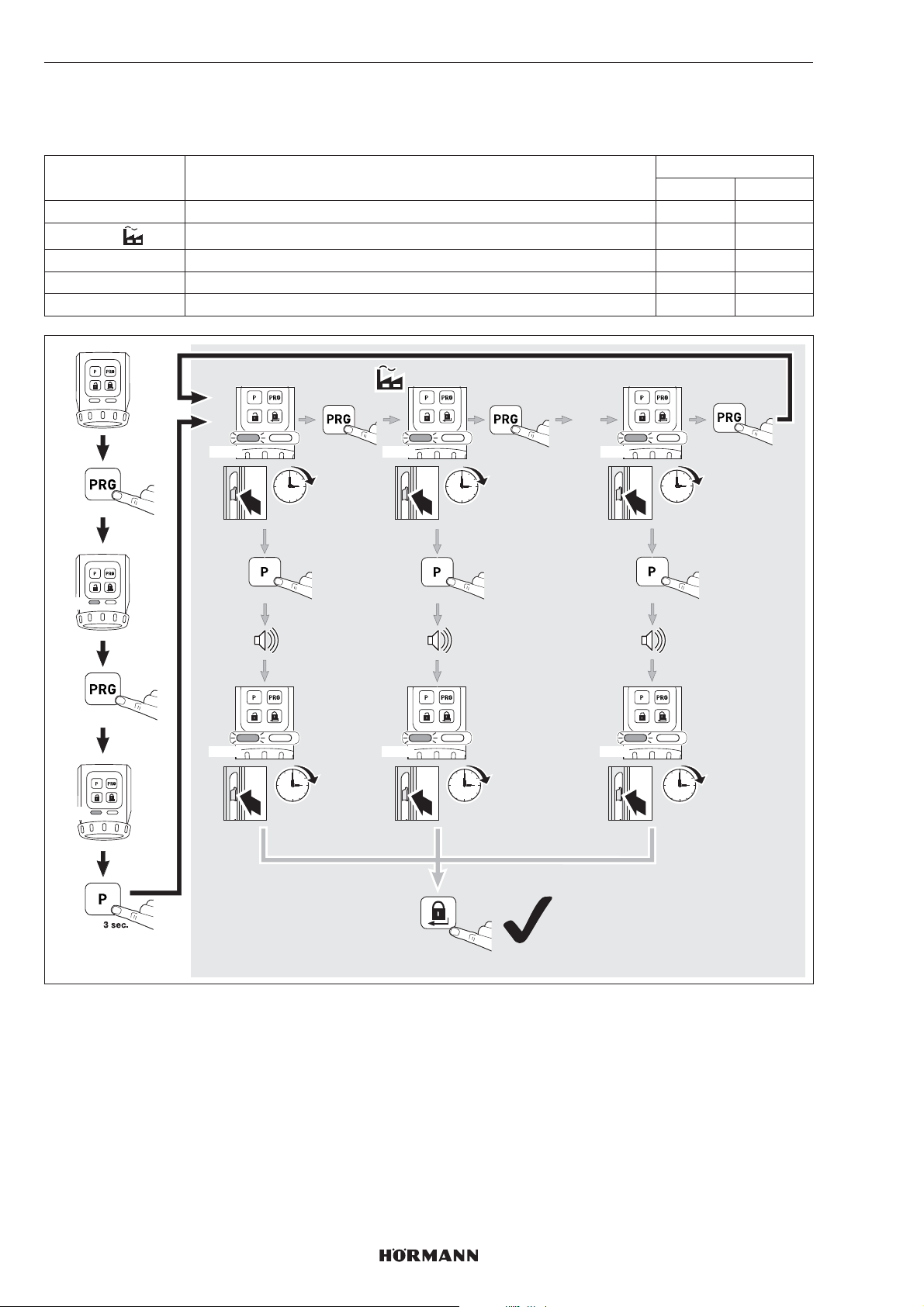
ESPAÑOL
7.2.3 Tiempo de retención del resbalón
Con el tiempo de retención del resbalón se puede ajustar el tiempo durante el que se mantiene abierto elresbalón para
abrir la puerta.
Parámetro Ajustes LED
izquierdo derecha
1 aprox. 1segundo 1 × YE
2
3 aprox. 5segundos 3 × YE
4 aprox. 10segundos 4 × YE
5 aprox. 20segundos 5 × YE
aprox. 3segundos 2 × YE
GN
YE
3 sec.
2 x
1x YE 2x YE 5x YE
1 sec.
3 sec.
1x YE 2x YE 5x YE
1 sec.
1x
3 sec.
3 sec.
3 sec.
1 x
…
1 x
20 sec.
3 sec.
20 sec.
74
2 x
4555360 B0 / 42-2023 / DX
Page 75
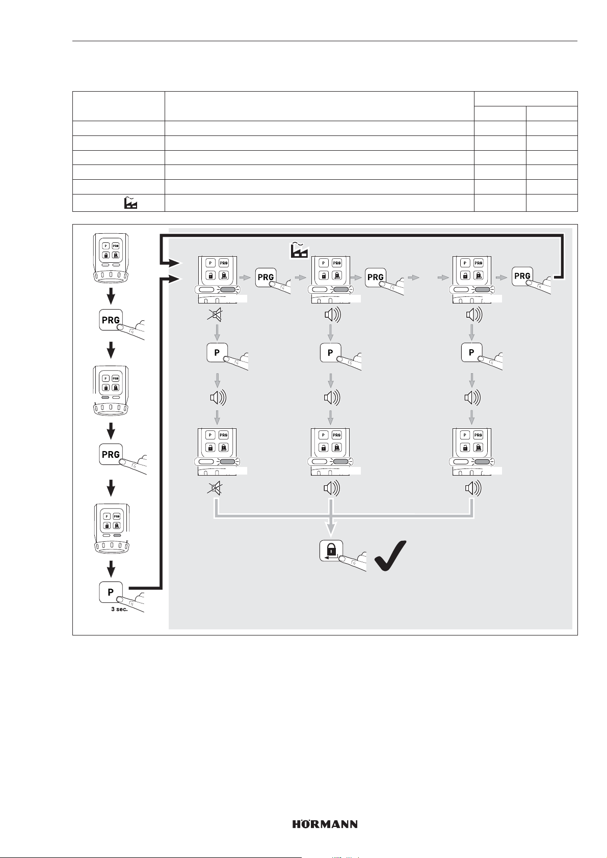
7.2.4 Transmisor de señales
Con estos parámetros se pueden ajustar las propiedades de la señal.
Parámetro Ajustes LED
izquierdo derecho
1 Apagado 1 × GN
2 Solo teclas 2 × GN
3 Solo posiciones finales 3 × GN
4 Solo posición final bloqueada 4 × GN
5 Teclas y posición final bloqueadas 5 × GN
6
Teclas y posiciones finales 6 × GN
ESPAÑOL
GN
3 sec.
3 x
GN
1x GN 2x GN 6x GN
3 sec.
1x GN 2x GN 6x GN
1x
3 sec.
2 x
1 x
…
1 x
3 sec.
4555360 B0 / 42-2023 / DX
75
Page 76
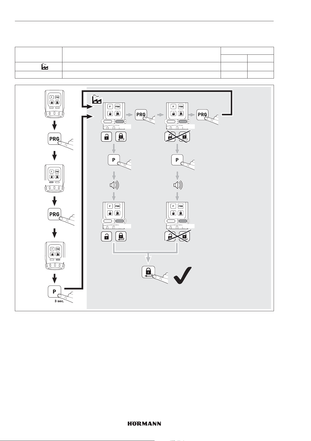
ESPAÑOL
7.2.5 Campo de sensores con teclas
Con estos parámetros se puede desactivar el manejo de la tecla de desbloqueo y de la tecla de bloqueo.
Parámetro Ajustes LED
izquierdo derecho
1
2 Desactivar 2 × RD
Activar 1 × RD
GN
3 sec.
4 x
RD
1x RD 2x RD
3 sec.
1x RD 2x RD
1x
1 x
3 sec.
76
2 x
4555360 B0 / 42-2023 / DX
Page 77
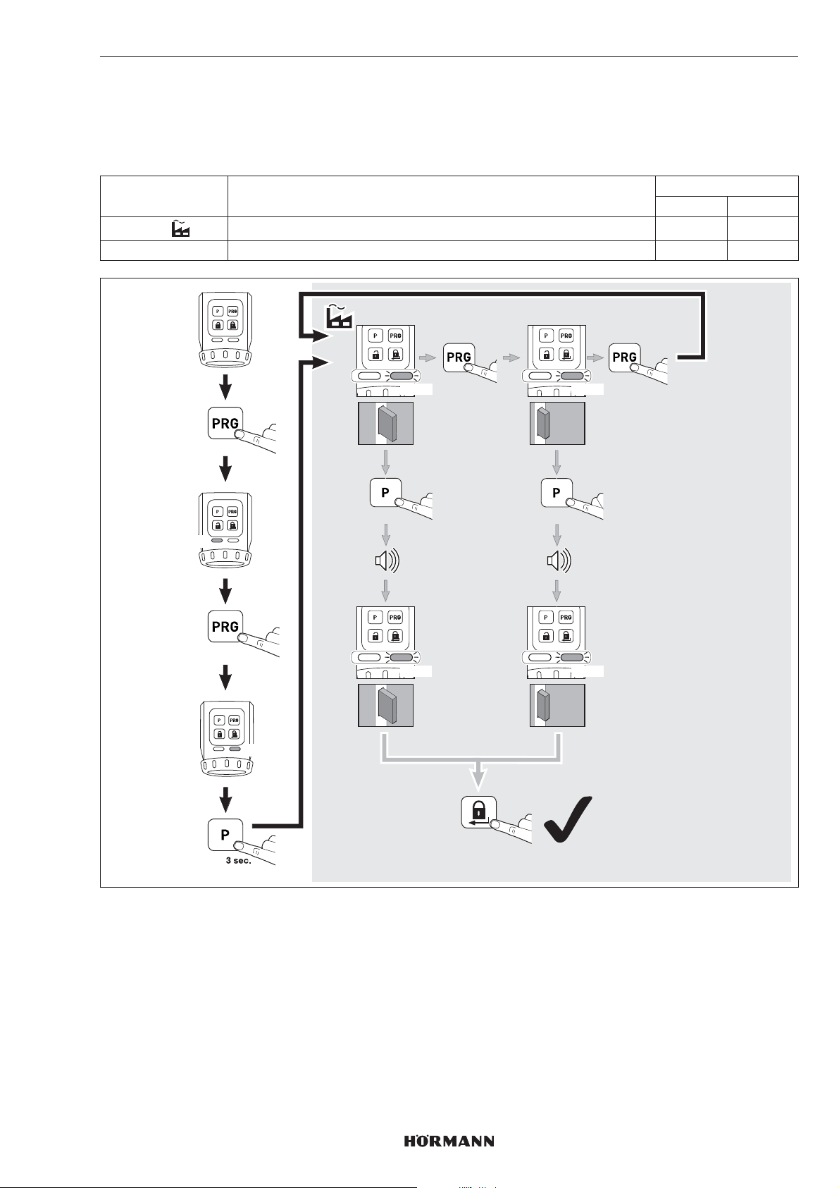
7.2.6 Reducción del bloqueo
Con estos parámetros se puede reducir un bloqueo de 2 giros a un bloqueo de 1 giro.
INDICACIÓN
Por motivos de seguridad, recomendamos conservar los ajustes de fábrica.
Parámetro Ajustes LED
izquierdo derecho
1
2 Solo un bloqueo 2×YE
Automático 1×YE
ESPAÑOL
GN
3 sec.
5 x
YE
1x YE 2x YE
3 sec.
1x YE 2x YE
1x
1 x
1x
3 sec.
1x
4555360 B0 / 42-2023/ DX
2 x
77
Page 78
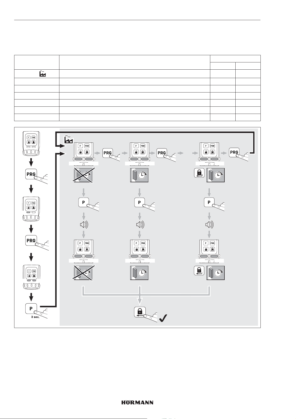
ESPAÑOL
7.2.7 Bloqueo de confort (bloqueo automático)
Con estos parámetros se puede ajustar si la cerradura se bloquea automáticamente transcurrido un tiempo definido o
después de pulsar una tecla y transcurrido un tiempo definido. Preste atención a que, antes de que transcurra el tiempo
definido, la puerta esté cerrada para garantizar el bloqueo seguro de la misma.
Parámetro Ajustes LED
izquierdo derecho
1
2 aprox. 30segundos después de alcanzar la posición final Bloqueado 2×GN 2×GN
3 aprox. 60segundos después de alcanzar la posición final Bloqueado 3×GN 3×GN
4 aprox. 120segundos después de alcanzar la posición final Bloqueado 4×GN 4×GN
5 aprox. 10segundos después de pulsar la tecla de bloqueo 5 × GN 5 × GN
6 aprox. 20segundos después de pulsar la tecla de bloqueo 6 × GN 6 × GN
7 aprox. 30segundos después de pulsar la tecla de bloqueo 7 × GN 7 × GN
inactivo 1 × GN 1 × GN
GN
GN
3 sec.
6 x
GN
1x GN 2x GN 7x GN
1x GN 2x GN 7x GN
1x GN 2x GN 7x GN
3 sec.
1x GN 2x GN 7x GN
1x
ca. 30 sec.
3 sec.
ca. 30 sec.
1 x
…
1 x
ca. 30 sec.
3 sec.
ca. 30 sec.
2 x
Desactivación breve del bloqueo de confort (parámetros 2, 3 y 4)
Puede desactivar el bloqueo de confort.
▶
Pulse la tecla PRG.
El bloqueo de confort está desactivado.
Con la siguiente orden de bloqueo, se activará de nuevo el bloqueo de confort.
78
4555360 B0 / 42-2023/ DX
Page 79
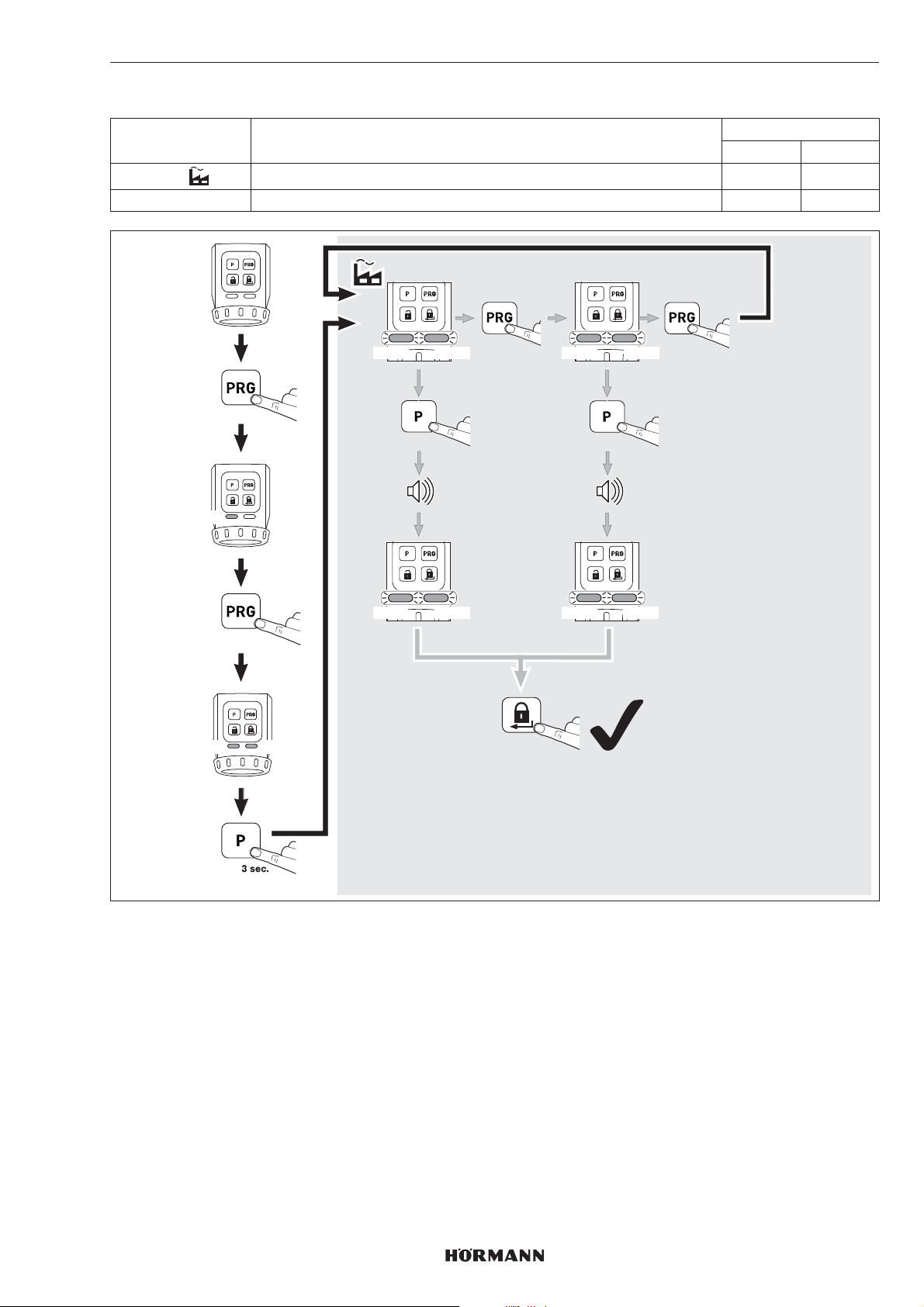
7.2.8 Restablecimiento de los ajustes del aparato
Parámetro Ajustes LED
izquierdo derecha
1
2 Recorridos de aprendizaje y funciones 2 × RD 2 ×RD
Solo recorridos de aprendizaje 1 × RD 1 ×RD
ESPAÑOL
GN
RD
3 sec.
7 x
RD
1x RD 2x RD
1x RD 2x RD
1x RD 2x RD
3 sec.
1x RD 2x RD
1x
2 x
1 x
3 sec.
4555360 B0 / 42-2023/ DX
79
Page 80
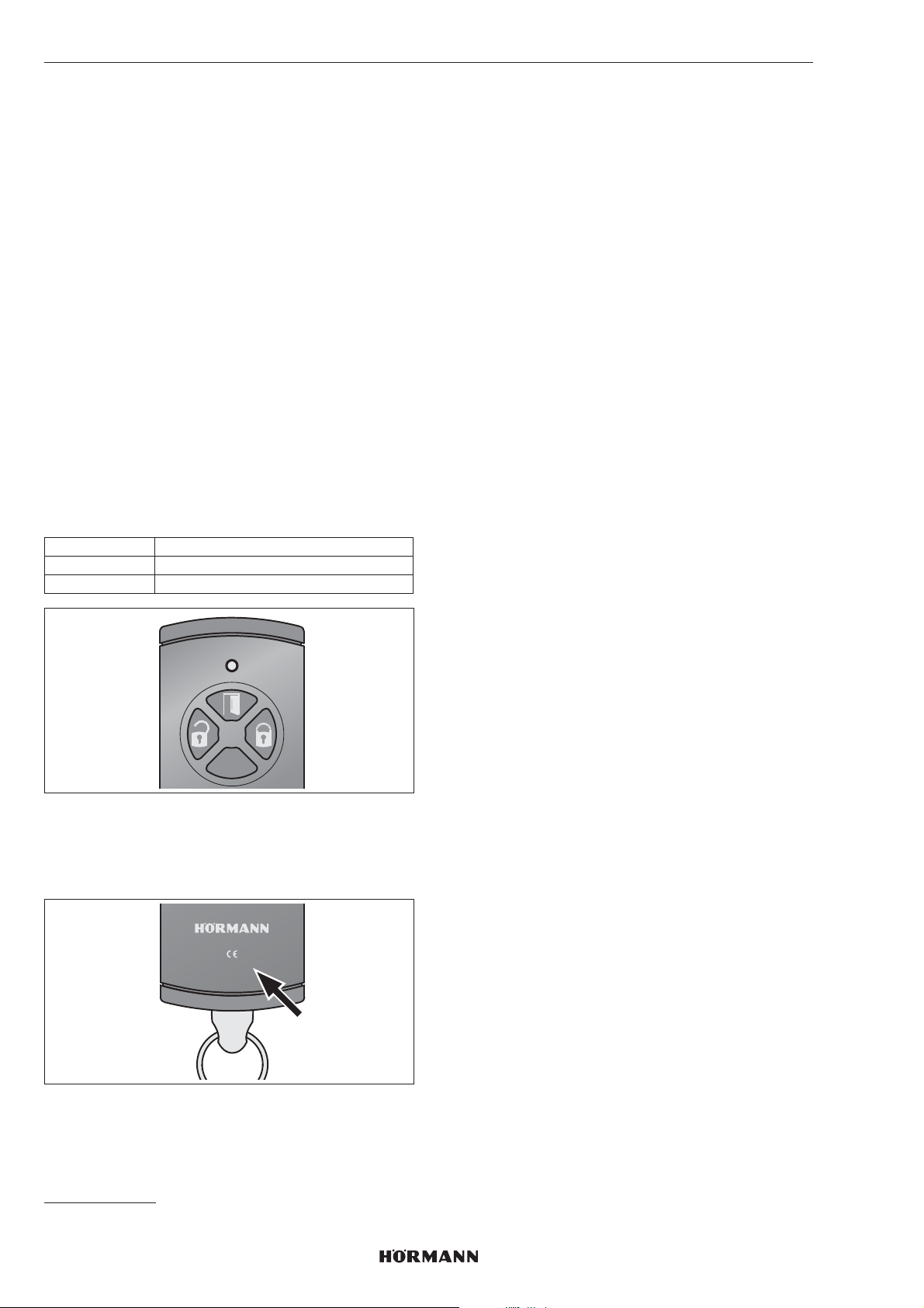
ESPAÑOL
8 Radiofrecuencia
8.1 Módulo por radiofrecuencia integrado
Se pueden transmitir máx. 100códigos de radiofrecuencia
de un emisor manual de 4 pulsadores HSE 4-SK-BS o del
emisor manual de seguridad HSSE 4-SK y repartirse entre
los canales existentes. Si se transmiten más de 100
códigos de radiofrecuencia, entonces se borrarán los
primeros códigos de radiofrecuencia programados.
No se pueden programar códigos de radiofrecuencia de
otros emisores* en el automatismo de cerradura de puerta.
A cambio, el emisor manual de 4 pulsadores HSE 4-SK-BS
y el emisor manual de seguridad HSSE4-SK pueden
transferir sus códigos de radiofrecuencia a otros emisores
BiSecur*.
8.2 Emisor manual
Junto con el automatismo de cerradura de puerta se
incluye un emisor manual de 4 pulsadores HSE4-SK
cuyos códigos de radiofrecuencia se deben programar en
el automatismo de la cerradura.
▶
Ver capítulo8.3
Asignación de teclas
izquierda desbloquear
arriba abrir
derecha bloquear
INDICACIÓN
No es posible transferir los códigos de radiofrecuencia del
emisor manual HSE4SK a otros emisores* si no existe un
índice o si el índice es -1 o -2.
HSE4-868-BS
0498-2
8.3 Programación del código
deradiofrecuencia de un emisor manual
HSE4-SK
Al programar el código de radiofrecuencia de un emisor
manual HSE4SK se memorizan los 3canales al mismo
tiempo.
1. Pulse 1 vez brevemente la tecla P del automatismo de
cerradura de puerta.
– El LED derecho parpadea lento en azul.
2. Mantenga el emisor manual frente al automatismo de
cerradura de puerta.
3. Pulse la tecla Abrir del emisor manual ymanténgala
pulsada.
– El LED se enciende en azul durante 2segundos y
se apaga.
– Después de 5segundos, el LED parpadea
alternadamente en color rojo y azul.
– El emisor manual envía el código
deradiofrecuencia.
4. Una vez reconocidos los códigos de radiofrecuencia,
el LED del automatismo parpadea rápido en azul.
– Después de 2segundos se apaga el LED.
5. Suelte el pulsador del emisor manual.
6. Pulse la tecla P para finalizar el proceso
deprogramación.
Se han programado los códigos deradiofrecuencia del
emisor manual.
8.4 Programación de los códigos
deradiofrecuencia de un emisor manual
deseguridad HSSE4SK
Al programar el código de radiofrecuencia deunemisor
manual de seguridad HSSE4-SK sememorizan los
3canales al mismo tiempo.
A continuación ya no se pueden programar más emisores
manuales HSE4-SK o HSSE4-SK con el índice -3 en el
automatismo. La transferencia a otros sensores* solo se
puede llevar a cabo mediante un proceso de copiado del
emisor manual de seguridad.
INDICACIÓN
Por su propia seguridad, le recomendamos borrar los
códigos de radiofrecuencia programados previamente en
el automatismo de cerradura de puerta si:
– va a programar un emisor manual deseguridad;
– ha realizado un reset del aparato en el emisor
manual de seguridad.
▶
Ver capítulo 8.3
Se han programado los códigos deradiofrecuencia del
emisor manual deseguridad.
INDICACIÓN
Para transferir/emitir el código de radiofrecuencia dispone
de 25segundos. Si la transferencia / emisión no se realiza
correctamente en este tiempo, deberá repetir el proceso.
* por ejemplo, emisor manual, Gateway
80
4555360 B0 / 42-2023 / DX
Page 81

ESPAÑOL
8.5 Borrar todos los códigos
deradiofrecuencia
No puede borrar los códigos de radiofrecuencia de
pulsadores de emisión o de funciones individuales.
▶
Pulse la teclaP y manténgala presionada.
– El LED parpadea lento durante 5segundos encolor
azul.
– El LED parpadea rápido durante 2segundos en
color azul.
– El LED se apaga.
Se han borrado todos los códigos deradiofrecuencia.
8.6 Modo reposo
Si el modo reposo está activado:
– ya no se puede manejar el automatismo
víaradiofrecuencia,
– aumenta la vida útil de la batería.
8.6.1 Activación del modo reposo
▶
Pulse la tecla de bloqueo del campo de sensores
durante 5segundos.
El automatismo se desplaza a la posición final
cerradura bloqueada, el modo reposo se activa yel
LED derecho parpadea 5 veces en azul.
INDICACIÓN
Si el automatismo ya está en la posición final, seactiva de
inmediato el modo reposo.
8.6.2 Desactivar el modo reposo
▶
Pulse la tecla de desbloqueo o la tecla de bloqueo del
campo de sensores.
El modo reposo está desactivado y el LED derecho se
ilumina durante 2segundos en azul.
INDICACIÓN
Al utilizar la rueda manual o la llave también sedesactiva el
modo reposo.
9 Funcionamiento
9.1 Manejo por campo de sensores
Para el manejo a través del campo de sensores
seutilizarán las teclas desbloquear / abrir y bloquear.
9.2 Manejo por radiofrecuencia
INDICACIÓN
Si el código de radiofrecuencia del pulsador del emisor
manual es heredado de otro emisor manual, presione la
primera vez el pulsador del emisor manual dos veces.
9.3 Manejo por rueda manual/llave
El manejo mediante la rueda manual/llave solo está
prevista en caso de emergencia.
INDICACIÓN
Después desbloquear mediante la rueda manual ocon una
llave, se realiza automáticamente un recorrido de
referencia del automatismo durante elsiguiente manejo.
Durante el mismo parpadea elLED izquierdo en rojo.
10 Estados de error
10.1 Recorridos de aprendizaje
Mensaje Causa Solución
Señal acústica
(60segundos)
yambos LED
parpadean en
amarillo
10.2 Funcionamiento normal
Mensaje Causa Solución
Señal acústica
durante
3segundos,
acontinuación
parpadea el LED
izquierdo durante
3segundos
enamarillo
Señal acústica
(60segundos) y el
LED izquierdo
parpadea
enamarillo
Señal acústica
(60segundos) y el
LED izquierdo
parpadea enrojo
Error durante
elrecorrido de
aprendizaje
Nivel de batería
bajo
Error durante
unrecorrido /
recorrido
dereferencia
Error durante
unrecorrido
dereferencia
Pulsar una tecla
en el campo de
sensores
Cambiar todas las
pilas al mismo
tiempo
Pulsar una tecla
en el campo
desensores
Nueva orden de
movimiento vía
radiofrecuencia
(solo abrir
odesbloquear)
Pulsar una tecla
en el campo
desensores
Nueva orden de
movimiento vía
radiofrecuencia
(solo abrir
odesbloquear)
4555360 B0 / 42-2023 / DX
81
Page 82
ESPAÑOL
11 Limpieza
ATENCIÓN
Daños en el automatismo de cerradura de puerta
debido a una limpieza incorrecta
Si para la limpieza del automatismo de cerradura de
puerta se utilizan detergentes inapropiados, pueden
dañarse la carcasa y los pulsadores.
▶
Limpie el automatismo de cerradura de puerta
únicamente con un paño limpio y húmedo.
12 Reciclaje
Elimine el embalaje de forma diferenciada.
Los dispositivos eléctricos y electrónicos deben
entregarse en los puntos de recogida previstos para
ello.
Deseche las pilas por separado. Cada consumidor
está legalmente obligado a entregar las pilas en un
punto de recogida local, regional o en un comercio.
13 Datos técnicos
Automatismo de cerradura depuerta
Modelo SmartKey
Frecuencia 868MHz
Potencia de transmisión máx. 10mW(EIRP)
Alimentación detensión • 4 pilas de 1,5V, tipoAA
(LR06), alcalina de
manganeso
o bien
• 4 acumuladores de 1,2V,
tipo: AA (HR6), níquel-metal
hidruro
Temperatura ambiente
admisible
Índice de protección IP20
0°C hasta +40°C
14 Declaración UE de conformidad
Por la presente, Hörmann KG Verkaufsgesellschaft declara
que el tipo de instalación por radiofrecuencia del
automatismo de cerradura de puerta vía radiofrecuencia
Smartkey cumple con la normativa 2014/53/UE.
En la siguiente dirección de internet podrá encontrar el
texto completo de la declaración de conformidad de la UE:
www.hoermann-docs.com/277127
82
4555360 B0 / 42-2023 / DX
Page 83

Содержание
1 Введение .........................................................84
1.1 Используемые символы ..................................84
2 Указания по безопасности ...........................84
2.1 Использование по назначению ......................84
2.2 Использование не по назначению .................84
2.3 Указания по безопасности при
эксплуатации ....................................................84
3 Комплект поставки ........................................84
4 Описание .........................................................85
5 Монтаж ............................................................86
5.1 Проверка характеристик двери .....................86
5.2 Проверка двери и профильного цилиндра ...86
5.3 Отпиливание головки ключа ...........................86
5.4 Монтаж крепежной пластины ........................87
6 Ввод в эксплуатацию ....................................89
6.1 Вставьте батарейки .........................................89
6.2 Завершающие работы .....................................89
6.3 Программирование привода ..........................90
7 Функции ...........................................................91
7.1 1-ый уровень меню / функции .........................91
7.2 2-ой уровень меню / параметры .....................91
8 Радиосигнал .................................................100
8.1 Встроенный радиомодуль .............................100
8.2 Пульты ДУ .......................................................100
8.3 Программирование радиокодов пульта ДУ
HSE 4-SK в режиме обучения .......................100
8.4 Программирование радиокода пульта ДУ с
защитой от копирования HSSE 4-SK в
режиме обучения ...........................................100
8.5 Удаление всех радиокодов ...........................101
8.6 Нерабочий режим ..........................................101
9 Эксплуатация ................................................101
9.1 Управление с помощью сенсорной панели .101
9.2 Эксплуатация с помощью устройств
дистанционного управления .........................101
9.3 Управление с помощью регулировочного
колеса / ключа ................................................101
10 Состояния сбоя ............................................101
10.1 Рабочие циклы для программирования
врежиме обучения ........................................101
10.2 Нормальный режим .......................................101
11 Очистка ..........................................................102
12 Утилизация ....................................................102
13 Технические данные ....................................102
14 Заявление о соответствии
требованиям ЕС ...........................................102
РУССКИЙ
Без наличия специального разрешения запрещено
любоераспространение или воспроизведение данного документа, а
также использование и размещение где-либо его содержания.
Несоблюдение данного положения влечет за собой санкции в виде
возмещения ущерба. Все объекты патентного права (патенты,
полезные модели, зарегистрированные промышленные образцы и т.д.)
защищены. Право на внесение изменений сохраняется.
4555360 B0 / 42-2023 / DX
83
Page 84
РУССКИЙ
1 Введение
В данном руководстве содержится важная
информация об изделии, прежде всего, указания по
технике безопасности и предупреждения об опасности.
▶
Внимательно прочтите данное руководство.
▶
Бережно храните руководство в надежном месте.
УВЕДОМЛЕНИЕ
Выполняйте все предписания, нормы и правила
техники безопасности, действующие на месте
эксплуатации SmartKey.
1.1 Используемые символы
Важное указание
Допустимое расположение или
допустимая деятельность
Недопустимое расположение или
недопустимая деятельность
2.2 Использование не по назначению
Привод дверного замка нельзя использовать
– на противопожарных дверях без
подтверждающих документов
– на эвакуационных дверях
2.3 Указания по безопасности при
эксплуатации
ОПАСНО
Опасность в экстренной ситуации из-за запертой
двери в многоквартирном доме
При возникновении паники запертая дверь может
стать смертельно опасным препятствием в момент
покидания здания.
▶
Не устанавливайте привод дверного замка
навходной двери многоквартирного дома.
ВНИМАНИЕ
Негативное влияние факторов окружающей среды
на функционирование изделия
Несоблюдение этих требований может привести
кфункциональным сбоям!
Допустимая температура окружающей среды: от0°C
до +40°C.
Заводская настройка
2 Указания по безопасности
2.1 Использование по назначению
Привод дверного замка – это узел
– для запирания и отпирания двери спомощью
электродвигателя;
– для дверей с замками с максимум 2-мя
оборотами (2оборота ключа);
– для сухих помещений.
– для стальных огнестойких дверей Hörmann
T30 / EI
серий H3OD, STS30 / STU30, D65, STS / STU.
На стальных дверях с фурнитурой с короткой
накладкой используйте адаптерную пластину из
нержавеющей стали.
Внутри привода в гнездо вставлен ключ, спомощью
которого можно запирать, отпирать иоткрывать
профильный цилиндр. Импульс напривод подается,
например, с помощью
– сенсорной панели с клавишами,
– пульта ДУ,
– радиоуправляемого детектора отпечатков
пальцев,
– приложения Hörmann Homee App.
Использование не по назначению недопустимо.
Производитель не несет ответственности за ущерб,
возникший в результате неправильного использования
изделия или его использования непо назначению.
30 с круглыми розетками строительных
2
▶
После программирования или расширения системы
дистанционного управления необходимо провести
функциональное испытание.
▶
При вводе в эксплуатацию системы
дистанционного управления, а также
приеерасширении, следует использовать
исключительно оригинальные детали.
• Местные условия могут оказывать влияние
надальность действия дистанционного управления.
3 Комплект поставки
• Привод дверного замка SmartKey
• Крепежная пластина
• Пульт ДУ HSE4-SK-BS
• 4 батарейки по 1,5В, тип:AA (LR6), щелочная
марганцевая
• Крепежный материал
• Краткое руководство
84
4555360 B0 / 42-2023 / DX
Page 85
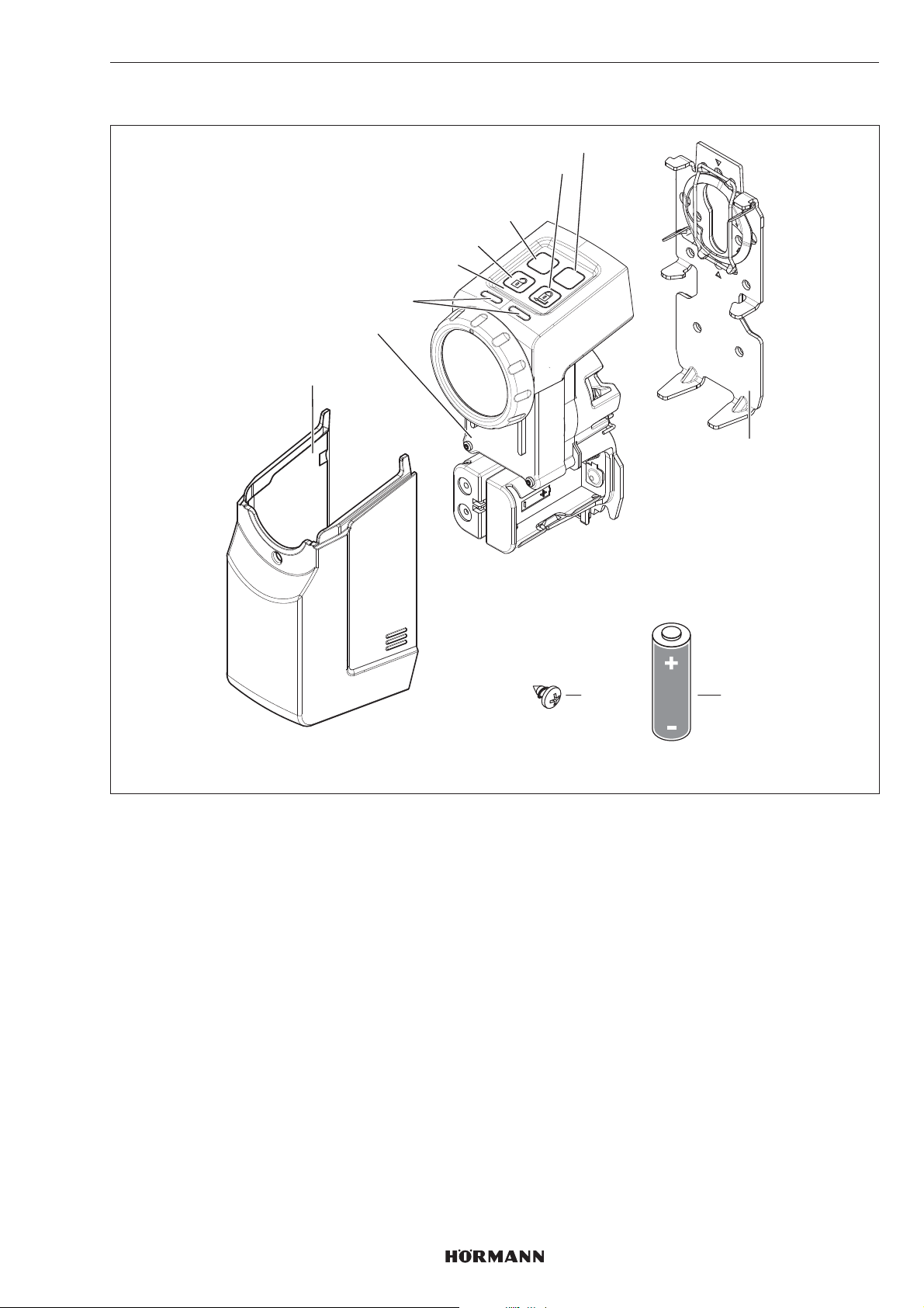
4 Описание
РУССКИЙ
8
7
6
5
4
P
PRG
3
2
1
9
1 Крышка
2 Привод
3 Светодиод (слева / справа), многоцветный
4 Сенсорная панель с клавишами
5 Клавиша разблокировки
6 Клавиша P
7 Клавиша блокировки
8 Клавиша PRG
9 Крепежная пластина
10 Батарейка 1,5В, тип:AA(LR6), щелочная марганцевая (4 ×)
11 Винт, 4,2 × 9,5мм (4 ×)
11
10
AA
4555360 B0 / 42-2023 / DX
85
Page 86
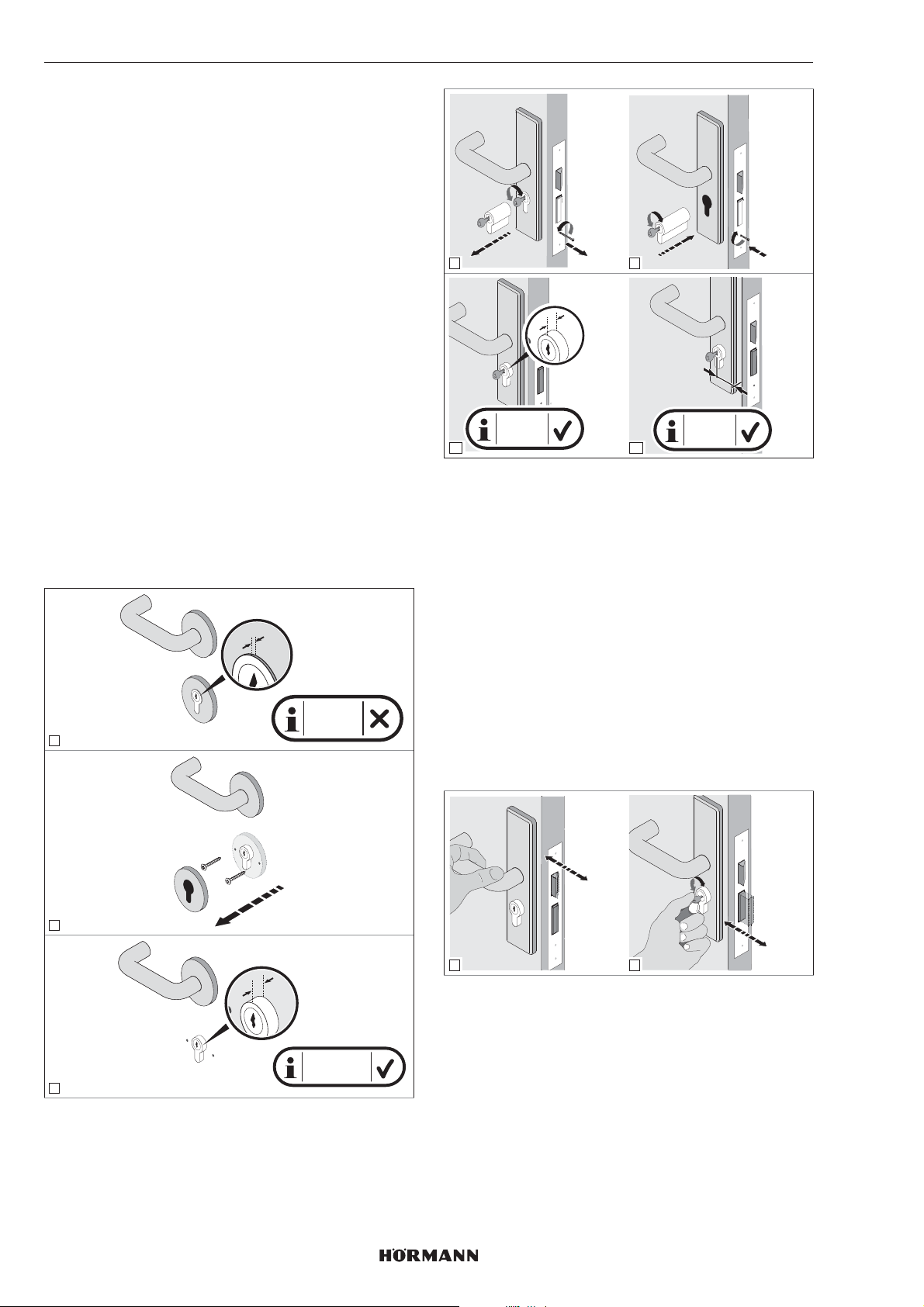
РУССКИЙ
5 Монтаж
Для привода дверного замка требуется ключ,
постоянно вставленный в профильный цилиндр.
Цилиндр должен
– представлять собой профильный цилиндр
всоответствии со стандартом DIN18252
иDINEN1303.
– обладать аварийной функцией и функцией
оповещения об опасности, т.е. если изнутри
вставлен ключ, цилиндр можно снаружи открыть
другим ключом.
2.
3.
4
1.
1.
2.
5
3.
5.1 Проверка характеристик двери
С внутренней стороны двери необходим выступ
цилиндра 7 – 12мм.
▶
Замените цилиндр, если
– цилиндр не имеет аварийной функции ифункции
оповещения об опасности
– выступ цилиндра составляет менее 7мм
СОВЕТ
Мы рекомендуем, по возможности, устанавливать
привод прямо на дверном полотне.
Расстояние от центральной точки отверстия под ключ
до наружной кромки двери или коробки должно
составлять как минимум 35мм, в противном случае
после монтажа дверь будет не открыть.
X
X < 7 mm
1
X
Y
X = 7-12
6
mm
7
Y ≥ 35
mm
5.2 Проверка двери и профильного
цилиндра
Дверь и профильный цилиндр должны находиться в
безупречном техническом состоянии и иметь легкий
ход.
▶
Перед монтажом привода дверного замка
проверьте настройки своей двери и цилиндра.
▶
Проверьте, запирается ли Ваш замок на1илина 2
оборота.
▶
Проверьте, возможно ли на открытой
иназакрытой двери одинаковое запирание (на1
оборот или на 2 оборота). Если назакрытой двери
с 2-оборотным запиранием возможно запирание
только на 1 оборот, топрограммирование пути
перемещения ирабочих усилий привода надо
производить при закрытой двери.
86
check!
2
1
X
2
check!
5.3 Отпиливание головки ключа
1. Отоприте дверь.
X = 7-12 mm
3
2. Отмерьте 4– 7мм между профильным цилиндром и
головкой ключа.
3. Отпилите головку ключа.
4. Зачистите место распила.
5. Снова вставьте ключ в цилиндр.
4555360 B0 / 42-2023/ DX
Page 87
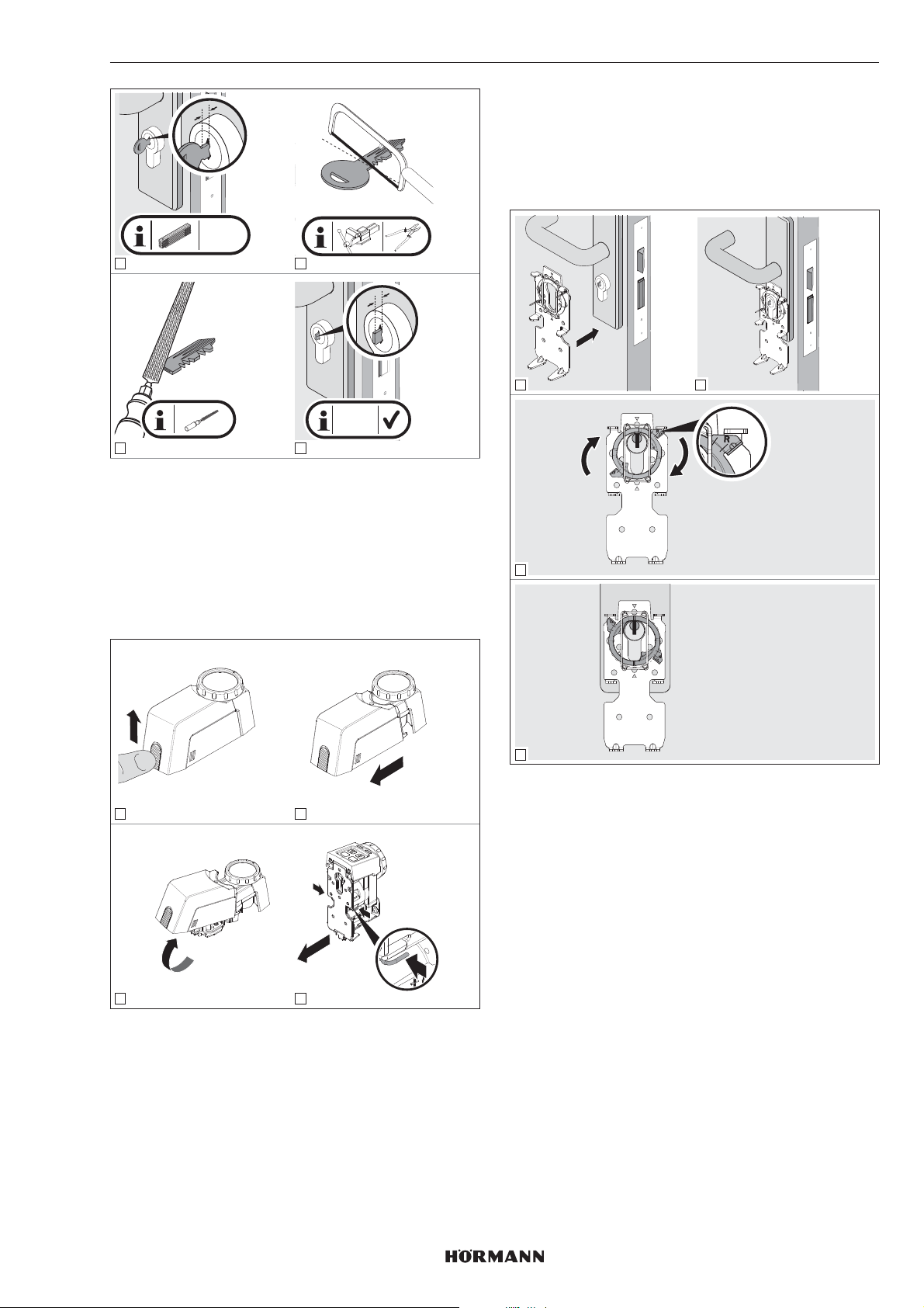
y
y = 4-7
mm
1 2
y
y = 4-7
mm
3
4
5.4 Монтаж крепежной пластины
1. Разблокируйте запирающее устройство
иудерживайте его в разблокированном состоянии.
2. Снимите с привода крышку.
3. Разблокируйте крепежную пластину.
4. Снимите крепежную пластину с задней стороны
привода.
РУССКИЙ
d. Крепежная пластина с привинчиваемой
розеткой
▶
см. главу5.4.4
5.4.1 Защемление крепежной пластины
спомощью зажима
1 2
3
1 2
PRG
P
1.
press!
2.
3
4
Монтаж крепежной пластины может осуществляться
четырьмя разными способами, которые можно
комбинировать друг с другом:
a. Защемление крепежной пластины спомощью
зажима
▶
см. главу5.4.1
b. Приклеивание крепежной пластины
▶
см. главу5.4.2
c. Привинчивание крепежной пластины
▶
см. главу5.4.3
4
▶
Поверните зажимное кольцо вправо до упора.
▶
Затем проверьте профильный цилиндр. Цилиндр
должен находиться в безупречном техническом
состоянии и иметь легкий ход.
4555360 B0 / 42-2023/ DX
87
Page 88
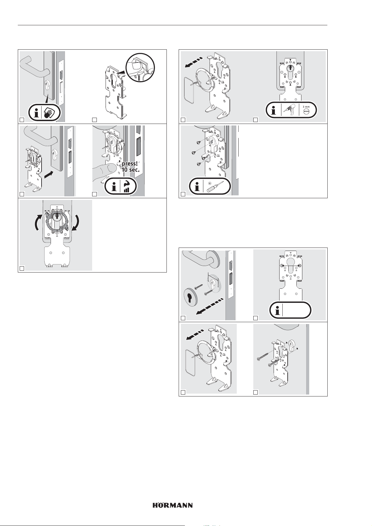
РУССКИЙ
5.4.2 Приклеивание крепежной пластины
1 2
3 4
5.4.3 Привинчивание крепежной пластины
1 2
3
▶
При установке на противопожарных дверях
используйте короткие саморезы.
PH2
5
Очищение поверхностей
▶
Используйте чистые безворсовые протирочные
салфетки без ароматизаторов.
▶
Используйте только подходящие чистящие
средства и не используйте оставляющие жирные
разводы бытовые моющие средства.
▶
Повторяйте очистку до тех пор, пока поверхность
не будет чистой и обезжиренной.
УКАЗАНИЕ
Всегда используйте подходящие чистящие средства и
средства по уходу. За поддержание поверхности в
идеальном состоянии ответственность несет владелец.
5.4.4 Крепежная пластина с
привинчиваемой розеткой
y
38 mm
y = 38 mm
1
3 4
▶
Следите за тем, чтобы не просверлить врезной
замок. При необходимости, укоротите винты.
2
88
4555360 B0 / 42-2023/ DX
Page 89
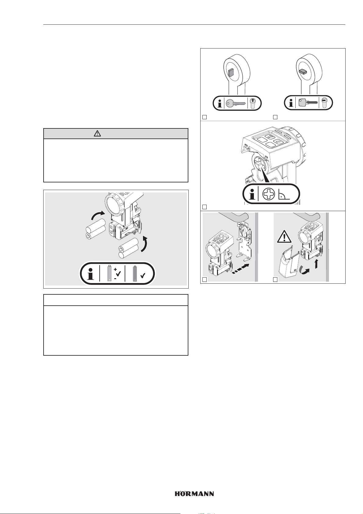
РУССКИЙ
6 Ввод в эксплуатацию
Как только батарейки установлены и синий светодиод
погас, привод дверного замка готов кэксплуатации.
6.1 Вставьте батарейки
Для эксплуатации привода дверного замка
используйте:
• 4 батарейки 1,5В, тип AA (LR6), щелочные
марганцевые
или
• 4 аккумулятора 1,2В, тип: AA (HR6), никельметаллогидридные
ОПАСНО
Опасность взрыва из-за батарейки неправильного
типа
Если батарейки заменить батарейками неправильного
типа, то есть опасность взрыва.
▶
Используйте только рекомендуемый
типбатарейки.
6.2 Завершающие работы
1 2
PRG
P
90°
3
+
AA
+
ACCU
ACCU
ВНИМАНИЕ
Повреждение привода дверного замка, вызванное
течью батареек
Батарейки могут течь, что, в свою очередь, может
привести к повреждению привода дверного замка.
▶
Удалите батарейки из привода дверного замка,
если он не используется в течение длительного
времени.
P
PRG
P
PRG
2.
click!
4
5
1.
1. Следите за правильным положением
одностороннего или двустороннего ключа.
2. Отрегулируйте под прямым углом крестообразный
шлиц с задней стороны привода с помощью
регулировочного колеса.
3. Установите привод на крепежной пластине.
– Привод фиксируется со щелчком.
4. Закройте привод крышкой.
– Крышка привода фиксируется со щелчком.
4555360 B0 / 42-2023/ DX
89
Page 90
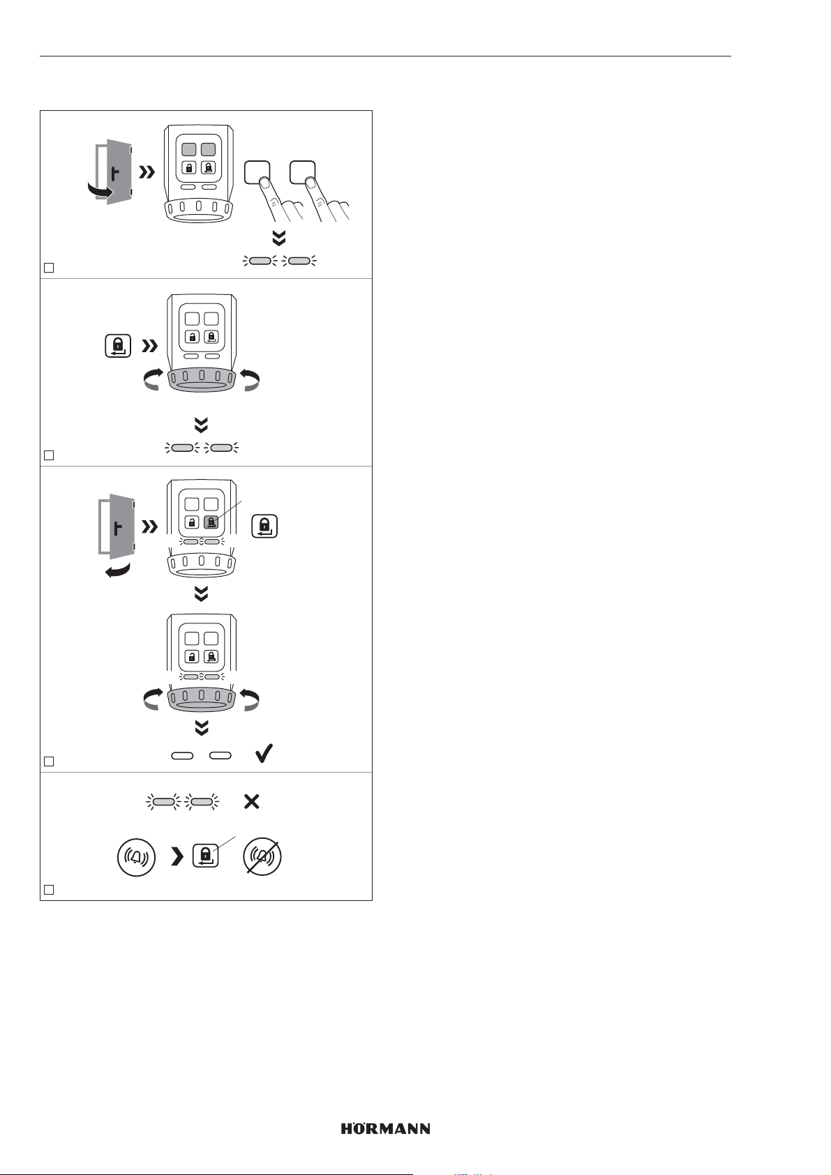
РУССКИЙ
6.3 Программирование привода
PRGP
press 3 sec.
+
1
ca. 3 sec. - 10 sec.
2
YE YE
YE YE
PRGP
press
PRGP
1. Нажмите одновременно клавиши P и PRG
иудерживайте их нажатыми, пока оба светодиода
не начнут мигать желтым цветом.
2. Нажмите клавишу блокировки.
Привод запоминает пути перемещения защелки и
ригеля. После достижения конечных положений
PRGP
данная операция завершается.
3. Закройте дверь.
4. Нажмите клавишу блокировки.
Привод «запоминает» необходимые усилия.
5. Привод запрограммирован.
Светодиоды гаснут.
УКАЗАНИЕ
Если светодиоды быстро мигают и подается
акустический сигнал, необходимо устранить причину
неисправности.
▶
см. главу10
6. Проверьте функции привода с помощью клавиш
сенсорной панели.
Время ожидания
Если в течение 60секунд не будет нажата ни одна
клавиша, привод дверного замка автоматически
вернется в рабочий режим.
Привод не запрограммирован.
YE YE
PRGP
YE YE
3
YE YE
press
=
4
Для того чтобы запрограммировать привод врежиме
обучения, должны быть выполнены следующие
условия:
• Привод не запрограммирован.
• Привод установлен на двери.
• Замок должен быть разблокирован, то есть все
ригели должны быть полностью задвинуты.
• Дверь открыта.
90
4555360 B0 / 42-2023 / DX
Page 91

РУССКИЙ
7 Функции
Функции привода дверного замка можно настраивать с
помощью клавиш P и PRG насенсорной панели. У
каждой функции есть несколько параметров, которые
позволяют произвести дальнейшие настройки. Перед
первым вводом в эксплуатацию все параметры
находятся в состоянии заводской настройки.
Изменения функций возможны только, когда привод
находится в нерабочем положении.
УКАЗАНИЕ
Учтите, что изменение заводской настройки может
привести к уменьшению срока службы батареек,
например при увеличении момента вращения
илискорости.
Вы должны настроить функции и соответствующие
параметры в соответствии с местными условиями и
индивидуальными пожеланиями.
7.2 2-ой уровень меню / параметры
Во 2-ом уровне меню заданы параметры функций из
1-ого уровня меню. Если Вы хотите настроить какойнибудь параметр, перейдите во 2-ой уровень меню.
1. Нажмите на клавишу P и удерживайте еенажатой в
течение 3секунд.
Привод дверного замка переходит из 1-ого во2-ой
уровень меню. В зависимости от настроенного
параметра соответствующий светодиод мигает тем
или иным цветом.
2. Выберите параметр с помощью многократного
кратковременного нажатия на клавишу PRG.
В зависимости от выбранной функции
соответствующий светодиод мигает тем илииным
цветом.
3. Активируйте выбранный параметр, нажав
на3секунды клавишу P.
Если параметр был активирован, светодиоды
ненадолго гаснут и раздается звуковой сигнал.
Затем с помощью светодиодов осуществляется
индикация актуального параметра.
4. Коротко нажмите на клавишу блокировки
1 нажатие = 1-ый уровень меню
2 нажатия = рабочий режим
Для прекращения настройки параметров:
▶
Нажмите 2 раза клавишу блокировки или
дождитесь окончания времени ожидания.
7.1 1-ый уровень меню / функции
В 1-ом уровне меню заданы функции привода дверного
замка.
1. Нажмите на клавишу PRG и удерживайте
еенажатой в течение 3секунд.
Привод дверного замка переходит изнормального
режима работы в 1-ый уровеньменю.
2. Выберите функцию с помощью многократного
кратковременного нажатия на клавишу PRG.
В зависимости от выбранной функции
соответствующий светодиод горит тем илииным
цветом.
Функции Светодиод Глава
слева справа
Момент вращения GN 7.2.1
Скорость RD 7.2.2
Время удерживания
защелки
Датчик сигналов GN 7.2.4
Сенсорная панель
склавишами
Сокращение запирания YE 7.2.6
Комфортное запирание GN GN 7.2.7
Возврат прибора
висходное состояние
(reset)
YE 7.2.3
RD 7.2.5
RD RD 7.2.8
Время ожидания
Если в течение 60секунд не будет нажата ни одна
клавиша, привод дверного замка автоматически
вернется в рабочий режим.
GN = зеленый, RD = красный, YE = желтый
4555360 B0 / 42-2023 / DX
91
Page 92
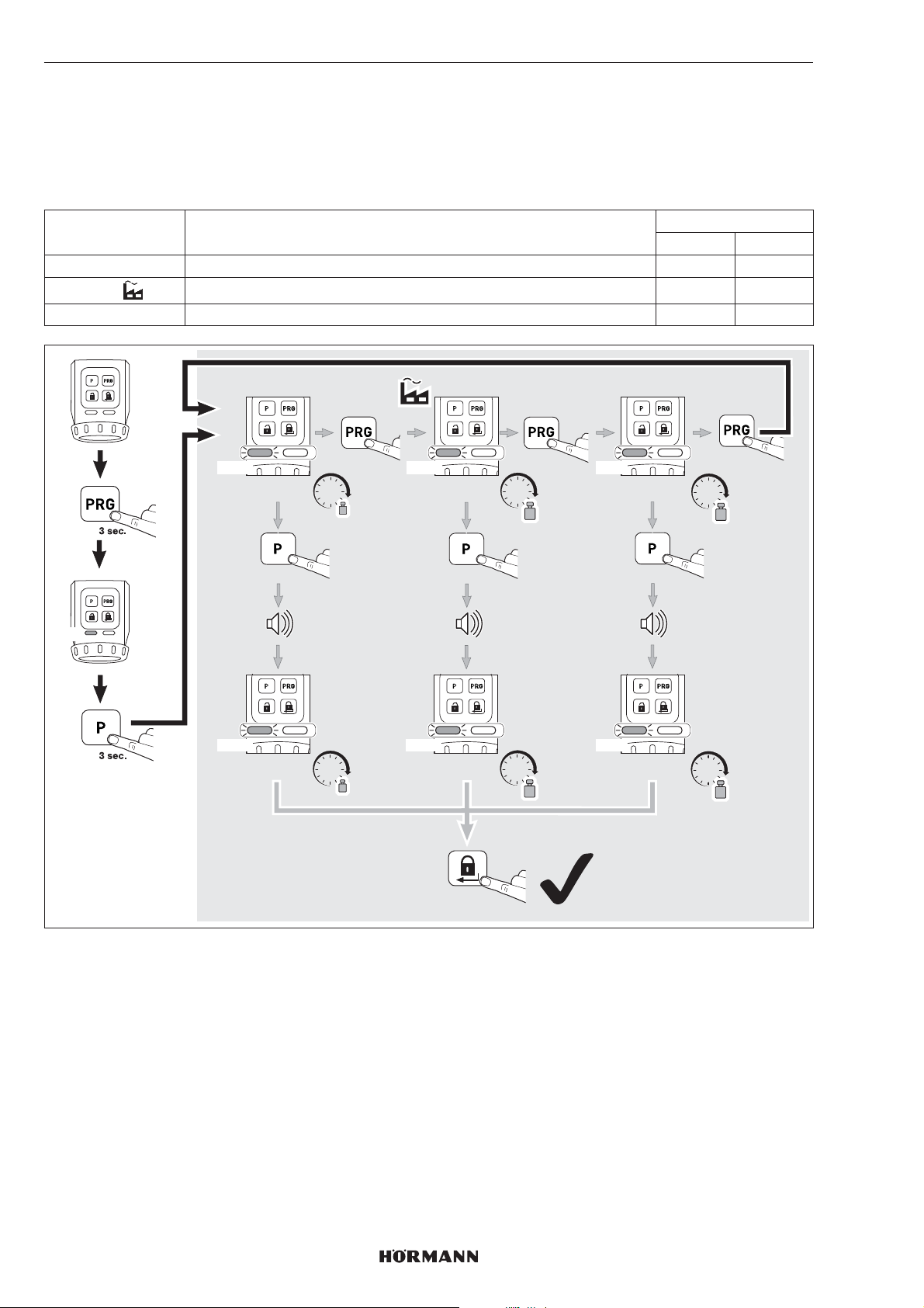
РУССКИЙ
7.2.1 Момент вращения
В зависимости от состояния двери или от состояния закрывания момент вращения защелки можно настроить с
помощью параметров 1 – 3.
УКАЗАНИЕ
Учтите, что увеличение момента вращения ведет к более высокой нагрузке на ключ.
Параметр Настройки Светодиод
слева справа
1 ок. 1,0Нм 1 × GN
2
3 ок. 1,5Нм 3 × GN
ок. 1,2Нм 2 × GN
GN
1x GN 2x GN 3x GN
ca. 1,0 Nm ca. 1,2 Nm
1x GN 2x GN 3x GN
ca. 1,0 Nm
Nm
3 sec.
Nm
1x
3 sec.
ca. 1,2 Nm
2 x
Nm
Nm
1 x
ca. 1,5 Nm
ca. 1,5 Nm
1 x
Nm
3 sec.
Nm
92
4555360 B0 / 42-2023 / DX
Page 93
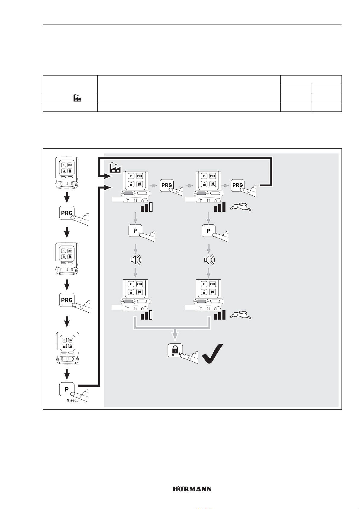
РУССКИЙ
7.2.2 Скорость
Скорость запирания, отпирания и открывания можно настроить с помощью 2-х параметров.
УКАЗАНИЕ
Учтите, что увеличение скорости ведет к более высокой нагрузке на ключ.
Параметр Настройки Светодиод
слева справа
1
2 Максимум 2 × RD
СОВЕТ
Мы рекомендуем оставить автоматическую настройку, поскольку она автоматически адаптируется кразличным
характеристикам двери.
Автоматический режим 1 × RD
GN
RD
3 sec.
1 x
1x RD 2x RD
3 sec.
1x RD 2x RD
1x
2 x
1 x
3 sec.
4555360 B0 / 42-2023 / DX
93
Page 94
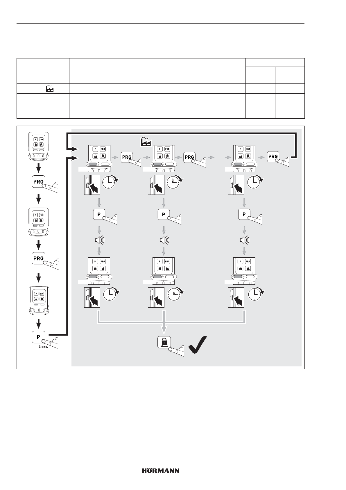
РУССКИЙ
7.2.3 Время удерживания защелки
Благодаря этой функции можно настроить время, в течение которого защелка будет удерживаться, чтобы дверь
оставалась открытой.
Параметр Настройки Светодиод
слева справа
1 ок. 1секунды 1 × YE
2
3 ок. 5 секунд 3 × YE
4 ок. 10секунд 4 × YE
5 ок. 20секунд 5 × YE
ок. 3 секунд 2 × YE
GN
YE
3 sec.
2 x
1x YE 2x YE 5x YE
1 sec.
3 sec.
1x YE 2x YE 5x YE
1 sec.
1x
3 sec.
3 sec.
3 sec.
1 x
…
1 x
20 sec.
3 sec.
20 sec.
94
2 x
4555360 B0 / 42-2023 / DX
Page 95
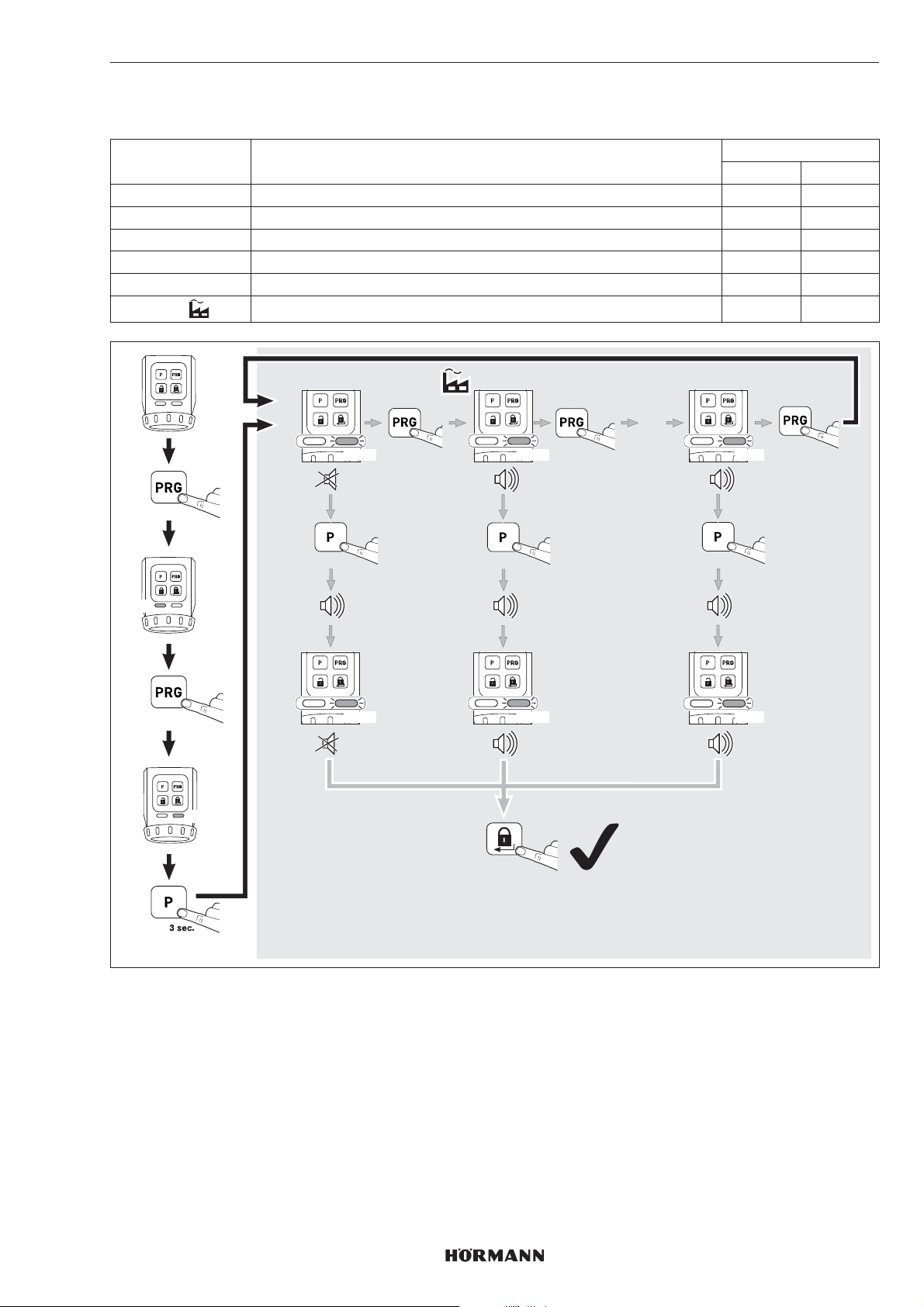
7.2.4 Датчик сигналов
С помощью этих параметров можно настроить характеристики сигналов.
Параметр Настройки Светодиод
слева справа
1 выкл. 1 × GN
2 только клавиши 2 × GN
3 только конечные положения 3 × GN
4 заблокировано только конечное положение 4 × GN
5 заблокированы клавиши и конечное положение 5 × GN
6
клавиши и конечные положения 6 × GN
РУССКИЙ
GN
3 sec.
3 x
GN
1x GN 2x GN 6x GN
3 sec.
1x GN 2x GN 6x GN
1x
3 sec.
2 x
1 x
…
1 x
3 sec.
4555360 B0 / 42-2023 / DX
95
Page 96
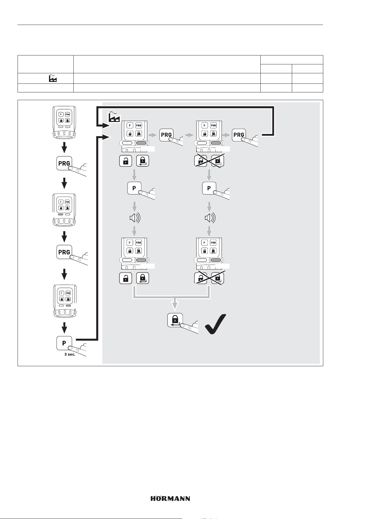
РУССКИЙ
7.2.5 Сенсорная панель с клавишами
С помощью этих параметров можно деактивировать управление клавишей разблокировки иклавишейблокировки.
Параметр Настройки Светодиод
слева справа
1
2 деактивировать 2 × RD
активировать 1 × RD
GN
3 sec.
4 x
RD
1x RD 2x RD
3 sec.
1x RD 2x RD
1x
1 x
3 sec.
96
2 x
4555360 B0 / 42-2023 / DX
Page 97
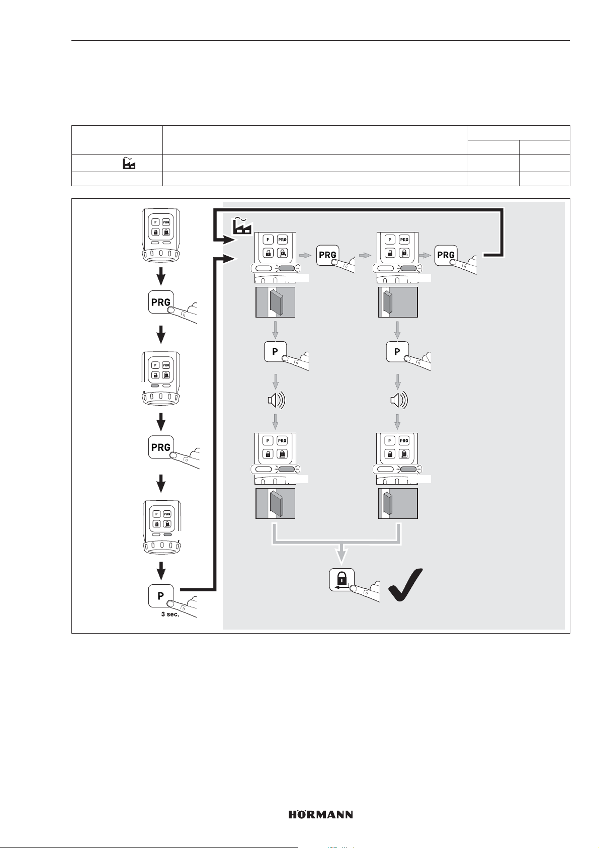
7.2.6 Сокращение запирания
С помощью этих параметров можно «сократить» запирание с 2-х оборотов до 1-го оборота.
УКАЗАНИЕ
Из соображений безопасности мы рекомендуем сохранить заводскую настройку.
Параметр Настройки Светодиод
слева справа
1
2 только одно запирание 2 ×YE
автоматический режим 1 × YE
РУССКИЙ
GN
3 sec.
5 x
YE
1x YE 2x YE
3 sec.
1x YE 2x YE
1x
1 x
1x
3 sec.
1x
4555360 B0 / 42-2023/ DX
2 x
97
Page 98
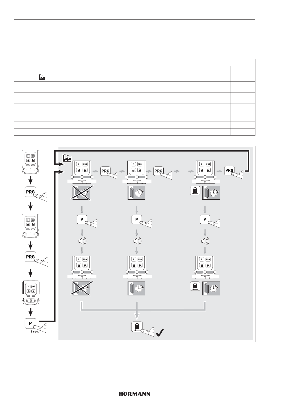
РУССКИЙ
7.2.7 Комфортное запирание (автоматическое запирание)
С помощью этих параметров можно настроить, будет ли замок автоматически запираться через определенное
установленное время или после нажатия на клавишу и через определенное, заранее установленное время. Следите
за тем, чтобы дверь была закрыта до истечения этого установленного времени, чтобы обеспечить надежное
запирание двери.
Параметр Настройки Светодиод
слева справа
1
2 примерно через 30секунд после достижения конечного положения
3 примерно через 60секунд после достижения конечного положения
4 примерно через 120секунд после достижения конечного положения
5 примерно через 10секунд после нажатия на клавишу блокировки 5 × GN 5 ×GN
6 примерно через 20секунд после нажатия на клавишу блокировки 6 × GN 6 ×GN
7 примерно через 30секунд после нажатия на клавишу блокировки 7 × GN 7 ×GN
неактивный 1 × GN 1 ×GN
2×GN 2×GN
Разблокировано
3×GN 3×GN
Разблокировано
4×GN 4×GN
Разблокировано
GN
GN
3 sec.
6 x
GN
1x GN 2x GN 7x GN
1x GN 2x GN 7x GN
1x GN 2x GN 7x GN
3 sec.
1x GN 2x GN 7x GN
1x
ca. 30 sec.
3 sec.
ca. 30 sec.
1 x
…
1 x
ca. 30 sec.
3 sec.
ca. 30 sec.
2 x
Кратковременная деактивация комфортного запирания (параметры 2, 3, и 4)
Вы можете деактивировать комфортное запирание.
▶
Нажмите на клавишу PRG.
Комфортное запирание деактивировано.
При следующей подаче команды блокировки комфортное запирание вновь активируется.
98
4555360 B0 / 42-2023/ DX
Page 99
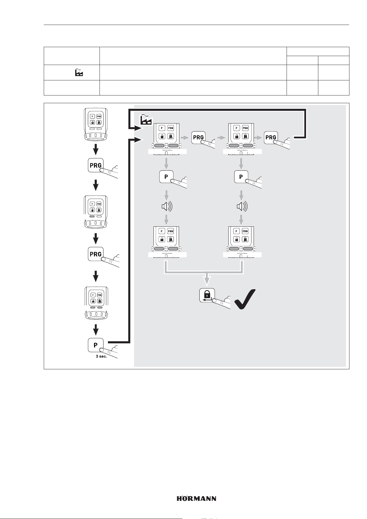
7.2.8 Возврат прибора в исходное состояние (reset)
Параметр Настройки Светодиод
слева справа
1
2 рабочие циклы для программирования врежимеобучения и
только рабочие циклы для программирования
врежимеобучения
функции
1×RD 1×RD
2×RD 2×RD
РУССКИЙ
GN
RD
3 sec.
7 x
RD
1x RD 2x RD
1x RD 2x RD
1x RD 2x RD
3 sec.
1x RD 2x RD
1x
2 x
1 x
3 sec.
4555360 B0 / 42-2023/ DX
99
Page 100
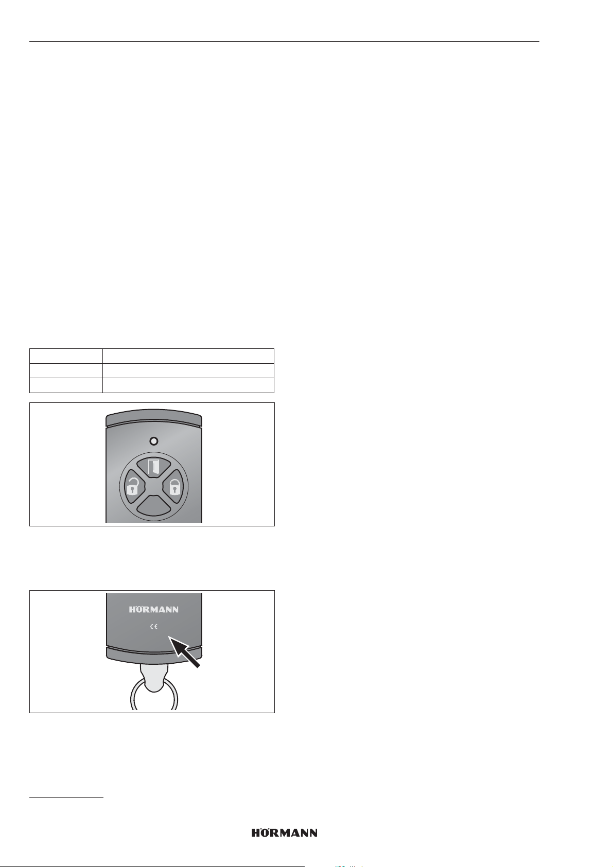
РУССКИЙ
8 Радиосигнал
8.1 Встроенный радиомодуль
С 4-клавишного пульта ДУ HSE 4-SK-BS или спульта
ДУ с защитой от копирования HSSE 4-SK возможна
передача до 100 радиокодов, которые могут
сохраняться на имеющихся каналах. Если передается
более 100 радиокодов, то радиокоды, которые были
запрограммированы раньше, удаляются.
Радиокоды других передатчиков* нельзя
запрограммировать в режиме обучения наприводе
дверного замка. Зато 4-клавишный пульт ДУ HSE
4-SK-BS и пульт ДУ с защитой откопирования HSSE
4-SK могут передавать своирадиокоды на другие
передатчики BiSecur*.
8.2 Пульты ДУ
К приводу дверного замка прилагается 4-клавишный
пульт ДУ HSE4-SK, радиокоды которого должны быть
запрограммированы наприводе дверного замка.
▶
см. главу8.3
Назначение клавиш
слева разблокировка
сверху открывание
справа запирание
УКАЗАНИЕ
Передача радиокодов с пульта ДУ HSE4SK надругие
передатчики* невозможна, если индекс отсутствует или
имеется индекс -1 или -2.
HSE4-868-BS
0498-2
8.3 Программирование радиокодов
пульта ДУ HSE 4-SK в режиме
обучения
При программировании радиокода HSE4SK
все3канала программируются в режиме обучения
одновременно.
1. Коротко нажмите 1 раз клавишу P привода
дверного замка.
– Правый светодиод медленно мигает синим
цветом.
2. Держите пульт ДУ перед приводом дверного замка.
3. Нажмите на пульте ДУ клавишу Открыть
иудерживайте ее нажатой.
– Светодиод горит синим цветом в течение
2секунд и затем гаснет.
– Через 5секунд светодиод поочередно мигает
красным и синим цветом.
– Пульт ДУ отправляет радиокоды.
4. Если радиокоды распознаны, светодиод привода
быстро мигает синим цветом.
– Через 2секунды светодиод гаснет.
5. Отпустите клавишу пульта ДУ.
6. Нажмите на клавишу P, чтобы завершить процесс
обучения.
Радиокоды пульта ДУ запрограммированы врежиме
обучения.
8.4 Программирование радиокода пульта
ДУ с защитой от копирования HSSE
4-SK врежиме обучения
При программировании радиокода пульта ДУ
сзащитой от копирования HSSE 4-SK все 3канала
программируются в режиме обучения одновременно.
После этого пульты ДУ HSE4-SK или HSSE4-SK
синдексом -3 больше не могут программироваться на
приводе. Дальнейшая передача на другие передатчики*
может происходить только через операцию
копирования с пульта ДУ с защитой откопирования.
УКАЗАНИЕ
Для Вашей же безопасности мы рекомендуем Вам
удалить запрограммированные ранее на приводе
дверного замка радиокоды,
– если Вы программируете в режиме обучения
пульт ДУ с защитой откопирования.
– если Вы произвели на пульте ДУ с защитой от
копирования возврат прибора висходное
состояние.
▶
см. главу8.3
* Например, пульт ДУ, шлюз Gateway
100
4555360 B0 / 42-2023 / DX
 Loading...